Maintenance and Service Guide HP ap5000 All-In-One Point of Sale System
© Copyright 2010 Hewlett-Packard Development Company, L.P. The information contained herein is subject to change without notice. Microsoft and Windows are trademarks of Microsoft Corporation in the U.S. and other countries. The only warranties for HP products and services are set forth in the express warranty statements accompanying such products and services. Nothing herein should be construed as constituting an additional warranty.
About This Book WARNING! Text set off in this manner indicates that failure to follow directions could result in bodily harm or loss of life. CAUTION: Text set off in this manner indicates that failure to follow directions could result in damage to equipment or loss of information. NOTE: Text set off in this manner provides important supplemental information.
iv About This Book
Table of contents 1 Product Features ............................................................................................................................................ 1 Standard Features ................................................................................................................................ 1 System Components ............................................................................................................................ 2 Bottom I/O Panel Components .........
Solving VFD (Vacuum Florescent Display) Problems ........................................................................ 26 Solving MSR (Magnetic Stripe Reader) Problems ............................................................................. 27 Solving Audio Problems ..................................................................................................................... 28 Solving Printer Problems ...........................................................................................
Installing Additional Memory .............................................................................................................. 57 DIMMs ............................................................................................................................... 57 DDR2-SDRAM DIMMs ...................................................................................................... 57 Installing DIMMs ............................................................................................
Index ...................................................................................................................................................................
1 Product Features Standard Features The HP ap5000 All-In-One Point of Sale System features include: ● Water-resistant touch screen panel support. You can use a stylus, finger tip, finger nail, or credit card edge on the touch screen. ● Two-line customer facing vacuum fluorescent display (VFD). ● Three-track magnetic strip reader (MSR) integrated into the system. ● Advertising display panel allows you to insert and display print advertisements (non-electrical).
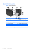
System Components Figure 1-1 System Components 1 2 1 Touch Screen 8 Print Advertisement Panel (nonelectrical) 2 Power LED 9 Base and Power Supply Housing 3 Magnetic Stripe Reader (MSR) 10 Bottom I/O Cover 4 VFD Customer Display 11 Power Button (underneath I/O cover) 5 Drive Cover 12 Side I/O cover 6 Adjustable VFD Hinge 7 Adjustable Touch Screen Hinge Rubber Feet1 (not illustrated) Unit is elevated so cables can route out from front, rear, or sides.
Bottom I/O Panel Components Figure 1-2 Bottom I/O Panel Connectors 1 Kensington Lock Slot 7 PS/2 Keyboard or Mouse Connector 2 Serial Connector (COM2, 5V) 8 Serial Connector (COM1, 5V) 3 Parallel Connector 9 Serial Connector (COM3, 12V) 4 RJ-45 Network Connector 10 VGA Connector 5 24V USB+POWER Connector 11 Universal Serial Bus (USB) Connectors 6 Power Button 12 Power Cord Connector Bottom I/O Panel Components 3
Side Panel Components Figure 1-3 Side Connectors 4 1 Primary Hard Drive 4 Microphone Connector (pink) 2 Secondary Hard Drive Bay 5 Universal Serial Bus (USB) Connector 3 Audio Line-Out Connector (green) Chapter 1 Product Features
2 Installing and Customizing the Software A keyboard is required to unbundle the software image. NOTE: If the computer was shipped with Windows Vista loaded, you will be prompted to register the computer with HP Total Care before installing the operating system. You will see a brief movie followed by an online registration form. Fill out the form, click the Begin button, and follow the instructions on the screen.
Installing or Upgrading Device Drivers When installing optional hardware devices after the operating system installation is complete, you must also install the drivers for each of the devices. If prompted for the i386 directory, replace the path specification with C:\i386, or use the Browse button in the dialog box to locate the i386 folder. This action points the operating system to the appropriate drivers.
3 Computer Setup (F10) Utility Computer Setup (F10) Utilities Use Computer Setup (F10) Utility to do the following: ● Change factory default settings. ● Set the system date and time. ● Set, view, change, or verify the system configuration, including settings for serial and parallel ports. ● View settings for processor and memory. ● Modify the boot order of bootable devices. ● Adjust the brightness of the LCD panel.
● Security ● Exit Use the arrow keys to select the appropriate heading, then press Enter. Use the arrow (up and down) keys to select the option you want, then press Enter. To return to the previous screen, press Esc. CAUTION: Do NOT turn the computer power OFF while the ROM is saving the Computer Setup (F10) changes because the CMOS could become corrupted. It is safe to turn off the computer only after exiting the F10 Setup screen.
Computer Setup—Advanced NOTE: Support for specific Computer Setup options may vary depending on the hardware configuration. WARNING! Setting items on this menu to incorrect values may cause your system to malfunction. Table 3-2 Computer Setup—Advanced Option Description SATA Configuration Allows you to configure the SATA ports as one of the following: Super IO Configuration ● SATA ● RAID Allows you to configure the Super IO chipsets.
Table 3-2 Computer Setup—Advanced (continued) ● ● ● ● ● ● 10 ◦ 5 ◦ 10 ◦ 11 Serial Port1 Standard Mode/5V – select the power mode for this serial port: ◦ 5V ◦ Standard Mode Serial Port2 Address – select the IO base address of the serial port ◦ Disabled ◦ 3F8 ◦ 2F8 ◦ 3E8 ◦ 2E8 ◦ 2F0 ◦ 2E0 Serial Port2 IRQ – select the IRQ for this serial port: ◦ 3 ◦ 4 ◦ 5 ◦ 10 ◦ 11 Serial Port2 Standard Mode/5V – select the power mode for this serial port: ◦ 5V ◦ Standard Mode Ser
Table 3-2 Computer Setup—Advanced (continued) ● ● ● USB Configuration 5 ◦ 10 ◦ 11 Serial Port3 Standard Mode/12V – select the power mode for this serial port: ◦ 12V ◦ Standard Mode MSR Port Address – select the IO base address of the serial port: ◦ Disabled ◦ 3E8 ◦ 2E8 ◦ 2F0 ◦ 2E0 ◦ 2D8 ◦ 2D0 MSR Port IRQ – select the IRQ for this serial port: ◦ 3 ◦ 4 ◦ 5 ◦ 10 ◦ 11 Allows you to configure the USB support: ● All USB Ports – enable or disable ● USB Port 3/4 – enable or
Table 3-2 Computer Setup—Advanced (continued) Restore on AC Power Loss Allows you to select system restart behavior after power loss: ● Power Off ● Power On ● Last State Wake On LAN Allows you to disable or enable wake-on-LAN to generate a wake event. HD Audio Allows you to disable or enable HD audio. Factory Recovery Boot Support Allows you to disable or enable factory recovery boot support. PXE ROM Allows you to disable or enable the PXE option ROM for the integrated/onboard LAN.
Table 3-4 Computer Setup—Security (continued) Change Supervisor Password Allows you to change the Supervisor Password. Change User Password Allows you to change the User Password. Computer Setup—Exit NOTE: Support for specific Computer Setup options may vary depending on the hardware configuration. Table 3-5 Computer Setup—Exit Option Description Save Changes and Exit Press Enter to exit saving changes. Discard Changes and Exit Press Enter to exit discarding changes.
4 Troubleshooting This chapter provides information on how to identify and correct minor hardware and software problems. If you encounter problems with the computer, refer to the tables in this chapter for probable causes and recommended solutions. Safety and Comfort WARNING! Misuse of the computer or failure to establish a safe and comfortable work environment may result in discomfort or serious injury. Refer to the Safety & Comfort Guide at http://www.hp.
Edition's online chat feature. Access HP Instant Support Professional Edition at: http://www.hp.com/ go/ispe. Access the Business Support Center (BSC) at http://www.hp.com/go/bizsupport for the latest online support information, software and drivers, proactive notification, and worldwide community of peers and HP experts. If it becomes necessary to call for technical assistance, be prepared to do the following to ensure that your service call is handled properly: ● Be in front of your system when you call.
● Reconfigure the system after installing a non–plug and play optional device. ● Be sure that all the needed device drivers have been installed. For example, if you are using a printer, you need a driver for that model printer. ● Remove all bootable media from the system before turning it on. ● If you have installed an operating system other than the factory-installed operating system, check to be sure that it is supported on the system.
Solving General Problems You may be able to easily resolve the general problems described in this section. If a problem persists and you are unable to resolve it yourself or if you feel uncomfortable about performing the operation, contact an authorized dealer or reseller. WARNING! When the computer is plugged into an AC power source, voltage is always applied to the system board.
Table 4-1 Solving General Problems (continued) There is no sound or sound volume is too low. Cause Solution System volume may be set low or muted. 1. Verify that the internal system audio is not disabled in F10 Setup. 2. Verify that any external speakers are properly connected and powered on, and that the volume control is set correctly. 3. Verify that the speakers are not muted in the operating system. 4. Use the operating system volume controls to increase the volume.
Table 4-1 Solving General Problems (continued) Poor performance is experienced. Cause Solution Too many applications running. 1. Close unnecessary applications to free up memory. Some applications run in the background and can be closed by right-clicking on their corresponding icons in the task tray. To prevent these applications from launching at startup, go to Start > Run and type msconfig.
Table 4-2 Solving Power Problems (continued) Power LED flashes red 4 times, once every second, followed by a 2 second pause, and the computer beeps 4 times; beeps stop after 5th iteration but LEDs continue flashing. Cause Solution Power failure (power supply is overloaded). 1. Check if a device is causing the problem: a. Remove all attached devices (hard drives, optical drives, printers, displays). b. Power on the system. c. If the system enters POST, power off and replace one device. d.
Solving Memory Problems If you encounter memory problems, some common causes and solutions are listed in the following table. CAUTION: Power may still be supplied to the DIMMs when the computer is turned off. To avoid damage to the DIMMs or the system board, you must unplug the computer power cord before attempting to reseat, install, or remove a DIMM. Table 4-3 Solving Memory Problems Memory count during POST is wrong. Cause Solution The memory modules may not be installed correctly.
If you encounter display problems, see the documentation that came with the monitor and the common causes and solutions listed in the following table. Table 4-5 Solving Display Problems Blank screen (no video). Cause Solution You may have a screen blanking utility installed or energy saver features are enabled. Touch the screen. System ROM is corrupted; system is running in Boot Block Emergency Recovery Mode (indicated by eight beeps). Reflash the system ROM with the latest BIOS image.
Table 4-5 Solving Display Problems (continued) The second monitor is blank (no video). CAUTION: The VGA port on the HP ap5000 All-In-One Point of Sale System is a powered VGA port. If you connect a stand-alone monitor to the VGA port that does not support the Powered VGA feature, make sure to plug it in prior to powering on the POS system in order to prevent possible damage to your monitor. Cause Solution The monitor was plugged into the system while the system was powered on.
Table 4-5 Solving Display Problems (continued) Characters on monitor are dim. Cause Solution The brightness controls are not set properly. Change the brightness level in F10 Setup: 1. From F10 Setup, select Advanced and click Manual Brightness Setting. 2. Select the correct setting, 0 providing the least brightness and 7 providing the most brightness. Blurry video or requested resolution cannot be set. Cause Solution Correct graphics driver may not be loaded or may be corrupt.
Table 4-5 Solving Display Problems (continued) Certain typed symbols do not appear correct. Cause Solution The font you are using does not support that particular symbol. Use the Character Map to locate and select the appropriate symbol. Click Start > All Programs > Accessories > System Tools > Character Map. You can copy the symbol from the Character Map into a document.
Solving VFD (Vacuum Florescent Display) Problems The VFD on the HP ap5000 system is connected via serial interface. When attached at the HP factory the VFD is installed on COM2 as the default location and COM2 is set to 5V mode. The HP ap5000 VFD can be connected either on COM2 or COM1 on the ap5000 unit; it cannot be used on COM3. Windows operating system supports serial port COM1/COM2, so no extra drivers are needed to be installed.
VFD not responding as expected. Cause Solution VFD not configured properly. Test the VFD using the utilities pre-installed on the image: 1. To test the COM port, access the HP ap5000 VFD Windows Utility from Star > HP Point of Sale Information > VFD for ap5000 > Windows Test Utility > HP ap5000 VFD Windows Utility. 2. Select the COM port from the drop-down box or keep the default option; the ap5000 VFD is shipped by default on COM2 from the HP factory. 3.
Solving Audio Problems If you encounter audio problems, see the common causes and solutions listed in the following table. Table 4-6 Solving Audio Problems Sound cuts in and out. Cause Solution Processor resources are being used by other open applications. Shut down all open processor-intensive applications. Direct sound latency, common in many media player applications. In Windows XP only: 1. From the Control Panel, select Sounds and Audio Devices. 2.
Solving Printer Problems If you encounter printer problems, see the documentation that came with the printer and the common causes and solutions listed in the following table. Table 4-7 Solving Printer Problems Printer will not print. Cause Solution Printer is not turned on and online. Turn the printer on and make sure it is online. The correct printer drivers for the application are not installed. 1. Install the correct printer driver for the application. 2.
WARNING! When the computer is plugged into an AC power source, voltage is always applied to the system board. To reduce the risk of personal injury from electrical shock and/or hot surfaces, be sure to disconnect the power cord from the wall outlet and allow the internal system components to cool before touching. NOTE: Recommended actions in the following table are listed in the order in which they should be performed. Not all diagnostic lights and audible codes are available on all models.
Table 4-8 Diagnostic Front Panel LED and Beep Codes (continued) Activity Beeps Possible Cause Recommended Action Red Power LED flashes five times, once every second, followed by a two second pause. Beeps stop after fifth iteration but LEDs continue until problem is solved. 5 Pre-video memory error. CAUTION: To avoid damage to the DIMMs or the system board, you must unplug the computer power cord before attempting to reseat, install, or remove a DIMM. 1. Reseat DIMMs. 2.
NOTE: If you take the computer to an authorized reseller, dealer, or service provider for service, remember to provide the setup and power-on passwords if they are set. Refer to the number listed in the warranty or in the Support Telephone Numbers guide for technical assistance.
5 Serial ATA (SATA) Drive Guidelines and Features SATA Hard Drives Serial ATA Hard Drive Characteristics Drive voltages 3.3 V, 5 V, 12 V Jumpers for configuring drive N/A Data transfer rate 3.0 Gb/s NOTE: If an error is identified with a device upon boot up a POST error message may be displayed.
Hard Drive Capacities The combination of the file system and the operating system used in the computer determines the maximum usable size of a drive partition. A drive partition is the largest segment of a drive that may be properly accessed by the operating system. A single hard drive may therefore be subdivided into a number of unique drive partitions in order to make use of all of its space.
6 Routine Care and Disassembly Preparation This chapter provides general service information for the computer. Adherence to the procedures and precautions described in this chapter is essential for proper service. CAUTION: When the computer is plugged into an AC power source, voltage is always applied to the system board. You must disconnect the power cord from the power source before opening the computer to prevent system board or component damage.
Removing DIPs* from vinyl tray 2,000 V 4,000 V 11,500 V Removing DIPs* from Styrofoam 3,500 V 5,000 V 14,500 V Removing bubble pack from PCB 7,000 V 20,000 V 26,500 V Packing PCBs in foam-lined box 5,000 V 11,000 V 21,000 V *These are then multi-packaged inside plastic tubes, trays, or Styrofoam. NOTE: 700 volts can degrade a product. Preventing Electrostatic Damage to Equipment Many electronic components are sensitive to ESD.
Grounding the Work Area To prevent static damage at the work area, use the following precautions: ● Cover the work surface with approved static-dissipative material. Provide a wrist strap connected to the work surface and properly grounded tools and equipment. ● Use static-dissipative mats, foot straps, or air ionizers to give added protection. ● Handle electrostatic sensitive components, parts, and assemblies by the case or PCB laminate. Handle them only at static-free work areas.
Operating Guidelines To prevent overheating and to help prolong the life of the computer: ● Keep the computer away from excessive moisture, direct sunlight, and extremes of heat and cold. ● Operate the computer on a sturdy, level surface. Leave a 10.2-cm (4-inch) clearance on all vented sides of the computer and above the monitor to permit the required airflow. ● Never restrict the airflow into the computer by blocking any vents or air intakes.
● For stubborn stains, use isopropyl (rubbing) alcohol. No rinsing is needed as the alcohol will evaporate quickly and not leave a residue. ● After cleaning, always wipe the unit with a clean, lint-free cloth. ● Occasionally clean the air vents on the computer. Lint and other foreign matter can block the vents and limit the airflow. Cleaning the Keyboard Follow all safety precautions in General Cleaning Safety Precautions on page 38 before cleaning the keyboard.
Service Considerations Listed below are some of the considerations that you should keep in mind during the disassembly and assembly of the computer.
Lithium Coin Cell Battery The battery that comes with the computer provides power to the real-time clock and has a minimum lifetime of about three years. See the appropriate removal and replacement chapter for the chassis you are working on in this guide for instructions on the replacement procedures. WARNING! This computer contains a lithium battery. There is a risk of fire and chemical burn if the battery is handled improperly.
7 Removal and Replacement Procedures Adherence to the procedures and precautions described in this chapter is essential for proper service. After completing all necessary removal and replacement procedures, run the Diagnostics utility to verify that all components operate properly. NOTE: Not all features listed in this guide are available on all computers.
Removing the Side I/O Cover To remove the side I/O cover, pull out on the center of the cover (1) and rotate the cover off (2). Figure 7-2 Removing the Side I/O Cover Removing the Drive Cover To remove the drive cover, loosen the screw that holds the cover in place (1), rotate the cover back (2), and pull the cover off the display head (3). NOTE: The drive cover screw is captive, therefore it does not disengage from the drive cover when loosened.
Routing Cables When connecting peripherals to the bottom I/O panel, route the peripheral cables through the bottom of the base and out the center hole at the top of the base before connecting. Figure 7-4 Routing Cables Adjusting the Tilt The main touch screen display has a 90 degree tilt range. The VFD customer display has an 80 degree tilt range.
Figure 7-6 Adjusting the VFD Customer Display Tilt Using the Print Advertising Panel This is a non-electrical panel. NOTE: There is a clear protective film on the interior and exterior side of the panel that end-user must remove.
You can insert a print advertisement into the panel on the system's base. A print advertisement template is available on the system's hard drive. 1. Press inward on the two sides of the advertising panel (1) and pull the cover of the panel off the system's base (2). Figure 7-7 Removing the Print Advertisement Panel Cover 2. Insert a print advertisement behind the panel cover. NOTE: A print advertisement panel template is available on the system's hard drive.
Installing an HP/Kensington MicroSaver Security Cable Lock 1. Remove the bottom I/O cover (see Removing the Bottom I/O Cover on page 42). 2. Install the cable lock into the lock slot on the bottom I/O panel. Figure 7-9 Installing an HP/Kensington MicroSaver Security Cable Lock 3. Replace the bottom I/O cover.
Removing and Replacing the VFD Customer Display The VFD is the two-line customer facing vacuum fluorescent display. NOTE: The VFD default setting is in COM 1. You can use BIOS to configure the VFD to work in COM 2. If the VFD is not working, make sure it is connected to a working COM port. Use BIOS to determine the correct COM port. 1. Turn off the computer properly through the operating system, then turn off any external devices. 2. Disconnect the power cord from the power outlet.
6. Remove the two screws below the display screen (1) and slide the display off the system (2). Figure 7-11 Removing the VFD Customer Display 7. Route the serial cable of the new display through the center hole in the hinge area and connect the cable to the same COM port on the I/O panel that was used for the old display. NOTE: If you are replacing the VFD customer display with an LCD customer display, connect the VGA cable of the LCD customer display to the VGA connector on the I/O panel. 8.
9. If you are replacing the VFD customer display, slide the new customer display into the slot on the hinge (1) and insert the two screws that secure it in place (2). Figure 7-13 Replacing the VFD Customer Display 10. Attach the hinge bracket cover by placing the upper sides of the cover over the sides of the bracket (1) then pressing the bottom of the cover onto the bracket so that it snaps in place (2). Figure 7-14 Replacing the VFD Hinge Bracket Cover 11. Replace the bottom I/O cover. 12.
Removing and Replacing the Hard Drive CAUTION: Before you remove the old hard drive, be sure to back up the data from the old hard drive so that you can transfer the data to the new hard drive. 1. Turn off the computer properly through the operating system, then turn off any external devices. 2. Disconnect the power cord from the power outlet. CAUTION: Regardless of the power-on state, voltage is always present on the system board as long as the system is plugged into an active AC outlet.
5. To remove the hard drive from the plastic carrier, pull up on the two ends on one side of the carrier (1) and rotate the drive out of the carrier (2). Figure 7-16 Removing the Hard Drive from the Carrier 6. To insert the new drive in the carrier, hold the drive at a slight angle and place one side of the hard drive in the carrier (1), then press the other side straight down into the carrier (2).
7. To replace the hard drive, slide the drive firmly into the bay with the end of the drive that has the connector going in first. Figure 7-18 Replacing the Hard Drive 8. Replace the drive cover. 9. Reconnect the power cord and press the power button.
Removing and Replacing the Power Supply 1. Turn off the computer properly through the operating system, then turn off any external devices. 2. Disconnect the power cord from the power outlet. CAUTION: Regardless of the power-on state, voltage is always present on the system board as long as the system is plugged into an active AC outlet. You must disconnect the power cord to avoid damage to the internal components of the computer. 3.
7. Lift the power supply and its cables out of the base of the unit. Figure 7-20 Removing the Power Supply 8. Connect the external power cord to the power supply. 9. Route the circular end of the power cord through the hole at the top of the base and connect the power cord to the power connector on the bottom I/O panel. 10. Place the power supply into the base so that it is sitting on the metal tabs inside the base.
11. Replace the power supply bracket by sliding the slotted end into frame (1) and tightening the thumbscrew (2). Figure 7-22 Replacing the Power Supply Bracket 12. Replace the bottom I/O cover. 13. Turn the unit over and onto its base. 14. Plug the power cord into an electrical outlet and press the power button. Removing the Magnetic Strip Reader (MSR) The MSR is located on the side of the display head. 1. Turn off the computer properly through the operating system, then turn off any external devices.
8. To remove the MSR, remove the two screws covers and screws that attach the MSR to the display head (1), lift the MSR off the display head (2), and unplug the cable attached to the underside of the MSR (3). Figure 7-23 Removing the MSR Reverse these procedures to install the MSR. NOTE: Be sure to replace the screw covers when replacing the MSR.
In addition, the computer supports: ● 512Mbit and 1Gbit non-ECC memory technologies ● single-sided and double-sided DIMMs ● DIMMs constructed with x8 and x16 DDR devices; DIMMs constructed with x4 SDRAM are not supported NOTE: The system will not start if you install unsupported DIMMs. Installing DIMMs CAUTION: You must disconnect the power cord and wait approximately 30 seconds for the power to drain before adding or removing memory modules.
9. Remove the five screws that secure the display head to the display head housing. Two of the screws are located under the bottom I/O cover. The third screw is located under the drive cover. The fourth screw is located under the MSR. The fifth screw is located below the touch screen hinge. NOTE: Some models may have only four screws. The center screw shown below may not be included. Figure 7-24 Removing the Display Head Screws 10.
12. Open both latches of the memory module socket (1), and insert the memory module into the socket (2). NOTE: A memory module can be installed in only one way. Match the notch on the module with the tab on the memory socket. 13. Push the module down into the socket, ensuring that the module is fully inserted and properly seated. Make sure the latches are in the closed position (3). Figure 7-26 Installing a DIMM 14. Repeat steps 12 and 13 to install any additional modules. 15. Reassemble the unit.
8 Configuring the Software Calibrating the Touch Screen After the operating system is installed, you will need to calibrate the touch screen. NOTE: You may want to connect a mouse (not included) to the system for this procedure. 1. Launch the TouchMon utility by right-clicking on the TouchMon icon in the system tray and selecting 4 points calibration or selecting Start > All Programs > HP Touch > HP TouchMon Calibration. 2.
Configuring the MSR and VFD Customer Display To configure the MSR and VFD, refer to the HP Point of Sale Configuration Guide (available in English only). The guide is available on the system's hard drive. In Windows XP or Windows Embedded POSReady 2009, select Start > All Programs > HP Point of Sale Information to access the guide. In Windows 7, select Start > HP Point of Sale Information to access the guide.
A Connector Pin Assignments This appendix contains the pin assignments for many computer and workstation connectors. Some of these connectors may not be used on the product being serviced.
Serial Interface, Powered and Non-Powered Connector and Icon Pin Signal 1 Carrier Detect (5V or 12V if powered) 2 Receive Data 3 Transmit Data 4 Data Terminal Ready 5 Signal Ground 6 Data Set Ready 7 Request to Send 8 Clear to Send 9 Ring Indicator (5V or 12V if powered) Parallel Interface Connector and Icon 64 Pin Signal Pin Signal 1 Strobe 10 Acknowledge 2 Data Bit 0 11 Busy 3 Data Bit 1 12 Paper End 4 Data Bit 2 13 Select 5 Data Bit 3 14 Auto Linefeed 6 Data Bi
USB Connector and Icon Pin Signal 1 +5 VDC 2 - Data 3 + Data 4 Ground Pin Signal Powered USB Connector and Icon Left side 1 +5 VDC 2 - Data 3 + Data 4 Ground Right side 24V 2A, 48W Pin Signal 1 (Tip) Audio_In_Left 2 (Ring) Audio_In_Right 3 (Shield) Ground Pin Signal 1 (Tip) Audio_Out_Left 2 (Ring) Audio_Out_Right 3 (Shield) Ground Line-in Audio Connector and Icon (1/8” miniphone) 1 2 3 Line-out Audio Connector and Icon (1/8” miniphone) 1 2 3 USB 65
Monitor Connector and Icon 66 Pin Signal Pin Signal 1 Red Analog 9 +5V (fused) 2 Green Analog 10 Ground 3 Blue Analog 11 19V when the 10.4” LCD is detected, 0V when a standard monitor is detected 4 19V when the 10.
B Power Cord Set Requirements The power supplies on some computers have external power switches. The voltage select switch feature on the computer permits it to operate from any line voltage between 100-120 or 220-240 volts AC. Power supplies on those computers that do not have external power switches are equipped with internal switches that sense the incoming voltage and automatically switch to the proper voltage.
Country-Specific Requirements Additional requirements specific to a country are shown in parentheses and explained below. 68 Country Accrediting Agency Country Accrediting Agency Australia (1) EANSW Italy (1) IMQ Austria (1) OVE Japan (3) METI Belgium (1) CEBC Norway (1) NEMKO Canada (2) CSA Sweden (1) SEMKO Denmark (1) DEMKO Switzerland (1) SEV Finland (1) SETI United Kingdom (1) BSI France (1) UTE United States (2) UL Germany (1) VDE 1.
C Passwords and CMOS Clearing CMOS You cannot clear the CMOS on the HP ap5000 POS because you cannot remove the battery. However, can change default settings in the F10 Setup Utility. To reset all the Setup options to default values, including options for Ctrl+F10, press F9, or enter F10 Setup mode and select Load Defaults from the Exit menu. NOTE: This does not include updates to system date, system time, supervisor password, or user password.
D POST Diagnostic Front Panel LEDs and Audible Codes Many pre-video conditions on the HP ap5000 POS System can easiliy be diagnosed through various beep and LED codes. The beep and LED blinks repeat for five cycles. Thereafter, only the LED blinks will continue repeating. WARNING! When the computer is plugged into an AC power source, voltage is always applied to the system board.
Table D-1 Diagnostic Front Panel LEDs and Audible Codes (continued) Activity Beeps Possible Cause Recommended Action Red Power LED flashes four times, once every second, followed by a two second pause. 4 Power failure (power supply is overloaded). 1. Open the hood and ensure the 4 or 6-wire power supply cable is seated into the connector on the system board. 2.
Table D-1 Diagnostic Front Panel LEDs and Audible Codes (continued) 72 Activity Beeps Possible Cause Recommended Action Red Power LED flashes eight times, once every second, followed by a two second pause. 8 Invalid ROM based on bad checksum. 1. Reflash the system ROM with the latest BIOS image. 2. Replace the system board. Red Power LED flashes nine times, once every second, followed by a two second pause. 9 1.
E Backup and Recovery Recovery after a system failure is as complete as your most current backup. You should create your initial backup immediately after software setup. As you add new software and data files, you should continue to back up your system on a regular basis to maintain a reasonably current backup. The backup and recovery tool used depends on which Microsoft Windows operating system is installed on your computer.
You can also use the F11 recovery tool to restore your original factory hard drive image. Refer to Using F11 Recovery on page 74. Microsoft Windows XP Backup and Recovery In Microsoft Windows XP, use HP Backup and Recovery Manager to back up individual files and folders, back up the entire hard drive, create recovery points, or create a recovery disc set. In case of system failure, you can use the backup files to restore the contents of your computer.
F Hewlett-Packard Vision Diagnostics (Windows systems) NOTE: HP Vision Diagnostics is included on CD with some computer models only. The Hewlett-Packard Vision Diagnostics utility allows you to view information about the hardware configuration of the computer and perform hardware diagnostic tests on the subsystems of the computer. The utility simplifies the process of effectively identifying, diagnosing, and isolating hardware issues. The Survey tab is displayed when you invoke HP Vision Diagnostics.
Accessing HP Vision Diagnostics (Windows systems) To access HP Vision Diagnostics, you must burn the utility onto a CD or copy it onto a USB flash drive then boot to the CD or USB flash drive. It can also be downloaded from http://www.hp.com and either burned to CD or installed to a USB flash drive. See Downloading the Latest Version of HP Vision Diagnostics on page 77 for more information. NOTE: HP Vision Diagnostics is included with some computer models only.
Downloading the Latest Version of HP Vision Diagnostics 1. Go to http://www.hp.com. 2. Select the Support & Drivers link. 3. Select Download drivers and software (and firmware). 4. Enter your product name in the text box and press the Enter key. 5. Select your specific computer model. 6. Select your OS. 7. Select the Diagnostic link. 8. Select the Hewlett-Packard Vision Diagnostics link. 9. Select the Download button.
G Specifications Table G-1 Specifications Desktop Dimensions (in the desktop position) Height 17.16 in 43.6 cm Width 13.86 in 35.2 cm Depth 18.98 in 48.2 cm 24.36 lb 11.
Table G-1 Specifications (continued) Standard Operating Power 1 230 V/50 Hz 230 V/50 Hz Idle (Monitor on)– 47.3 W Idle (Monitor on)– 47.3 W Idle (Monitor off)– 36.7 W Idle (Monitor off)– 36.7 W Burnin Test V5.3– 77.82 W Burnin Test V5.3– 77.82 W 3DMark06–80.34 W 3DMark06–80.34 W 115 V/50 Hz 115 V/50 Hz Idle (Monitor on)– 46.93 W Idle (Monitor on)– 46.93 W Idle (Monitor off)– 31.97 W Idle (Monitor off)– 31.97 W Burnin Test V5.3– 74.51 W Burnin Test V5.3– 74.51 W 3DMark06–80.
Index A audible codes 14, 70 audio problems 28 B battery disposal 41 beep codes 14, 70 bottom I/O panel components 3 removing cover 42 C cable lock 47 cable routing 44 cautions AC power 35 electrostatic discharge 35 keyboard cleaning 39 keyboard keys 39 cleaning computer 38 safety precautions 38 CMOS backing up 69 components bottom I/O panel 3 side panel 4 system 2 computer specifications 78 computer cleaning 38 configuring COM port 61 customer display 50 MSR 50 touch screen 61 connector pin assignments 63
power supply removing and replacing power-on password 69 print advertising panel removing and replacing template 45 printer problems 29 problems audio 28 general 17 memory 21 monitor 21 power 19 printer 29 processor 21 processor problems 21 R removing bottom I/O cover 42 customer display 48 drive cover 43 hard drive 51 MSR 57 power supply 54 print advertising cover side I/O cover 43 touch screen 59 resetting CMOS 69 password jumper 69 54 45 spare part number Torx T-15 screwdriver 40 specifications comput