HP ProLiant ML110 Generation 2 Lights-Out 100 Remote Management Processor User Guide August 2005 (Second Edition) Part Number 390154-002 Rev A
© Copyright 2005 Hewlett-Packard Development Company, L.P. The information contained herein is subject to change without notice. The only warranties for HP products and services are set forth in the express warranty statements accompanying such products and services. Nothing herein should be construed as constituting an additional warranty. HP shall not be liable for technical or editorial errors or omissions contained herein. Confidential computer software.
Contents Operational overview ................................................................................................................... 5 Server management................................................................................................................................... 5 Server management features....................................................................................................................... 5 Installation ...................................................
Configuring virtual floppy from the CLP ............................................................................................ 24 Rebooting the server ...................................................................................................................... 24 User administration.................................................................................................................................. 25 Changing the password through a Web browser ....................................
Operational overview In this section Server management.................................................................................................................................. 5 Server management features...................................................................................................................... 5 Server management The HP ProLiant ML110 Generation 2 Lights-Out 100 Remote Management Processor delivers basic remote control of vital server resources and supports IPMI 2.0.
Installation In this section Lights-Out 100 remote management card kit contents ................................................................................... 6 Installing the Lights-Out 100 remote management card .................................................................................
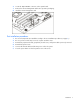
2. Locate the 30-pin RILOE II connector on the system board. 3. Remove the remote management card from its protective packaging. 4. Install the remote management card. Post-installation procedures 1. Be sure all components are installed according to the "Pre-installation procedures (on page 6)." 2. Be sure you have not left any loose tools or parts inside the server. 3. Reinstall any expansion boards, peripherals, board covers, and system cables previously removed. 4.
Configuration In this section Configuring network access....................................................................................................................... 8 Establishing user accounts ......................................................................................................................... 9 Configuring network access The server is connected to the network using a standard Ethernet cable.
6. Press the down arrow (↓) key to scroll down and enter a valid IP address, subnet mask, and gateway address (press the Tab key to move between address fields). 7. Press the down arrow (↓) key to scroll to the following settings, and set the parameters as needed (the following example shows configuring for remote management processor access using telnet and a Web page): 8.
Using Integrated Lights-Out 100 In this section New features ......................................................................................................................................... 10 SSL overview ......................................................................................................................................... 10 SSH overview ........................................................................................................................................
Lights-Out 100 requires a 2048-bit DSA key stored in PEM (base 64 encoded) format to be located on a TFTP server. For example, use the following instructions using the Win32 OpenSSL, downloaded from the Shining Light Productions website (http://www.slproweb.com/products/Win32OpenSSL.html). Use the following commands in a DOS window to generate the certificate: 1. Download Win32 OpenSSL. 2. Install and setup OpenSSL. 3.
Lights-Out 100 remote management processor can support simultaneous access from two SSH clients. After SSH is connected and authenticated, the command line interface is available. Before using SSH for the first time, perform the one-time setup procedure detailed in the "Importing an SSH key (on page 12)" section. The remote management processor supports: • SSH protocol version 2. • PuTTY 0.54, which is a free version of telnet and SSH protocol available for download on the Internet.
• filename—the file name of the key file. Using Secure Shell Using SSH When using a Secure Shell utility to connect to a server for the first time, the utility will prompt you to accept the server's public key, sometimes referred to as a host key. Accepting this key authorizes the utility to store a copy of the public key in its own database. The utility will automatically recognize the server when future connections are attempted, by comparing the public key to the one stored in its database.
• help • load • reset • set • show • start • stop • exit • version • Target—The default target is the /. The target can be changed by the cd command or by specifying a target on the command line. • Options—The valid options are: • -help/-h • -all/-a • Properties are the attributes of the target that can be modified. • Output—The output syntax is text. The valid Boolean values for any command are yes, no, true, false, y, n, t, and f.
/./ Targets system1/ map1/ Properties Verbs cd version exit show help The first line of information returned by the show command is the current context. In the example, / is the current context. Following the context is a list of sub-targets (Targets) and properties (Properties) applicable to the current context. The verbs (Verbs) section shows what commands are applicable to this context. The show command can also be specified with an explicit or implicit context as well as a specific property desired.
• set—Sets a property or set of properties to a specific value. • start—Causes a target to change state to a higher run level. • stop—Causes a target to change state to a lower run level. • version—Queries the version of the CLP implementation or other CLP elements. For example: hpiLO-> version status=0 status_tag=COMMAND COMPLETED SM-CLP Version 1.0 Specific commands CLP syntax for specific commands is found in the sections that also describe the functionality through the Web interface. IPMI 2.
Logging in through a Web browser 1. Browse to the IP address of the remote management processor to access the login screen. 2. Enter your user name and password. The default user name for the Administrator account is admin, and the default password is admin. The default user name for the Operator account is Operator, and the default password is Operator. Logging in through the CLP To log in to the remote management processor through the CLP and enter Terminal mode: 1.
Browser main menu options From the main menu, you can access all of the basic remote management capabilities of the remote management processor.
3. Press the down arrow (↓) key to scroll down to the Console Redirection, and press the Enter key to enter the sub-menu. 4. Select Enable. 5. Press the Esc key to return to the previous screen, or press the F10 key to save the changes and exit Setup. 6. Follow the instructions in the "Additional network settings (on page 26)" section to set or obtain a valid IP address. 7. Press the F10 key to save the changes and exit Setup. 8.
Controlling server power from a Web browser 1. Click Virtual Power on the main menu navigation bar. 2. Select the Power Control Option, and click Apply to initiate the Chassis Action. 3. To light the Chassis Identify LED, select the Chassis Locater LED on interval and click Identify. Controlling server power through the CLP 1. Log into the remote management processor CLP as described in the "Logging in to the remote management processor (on page 16)" section. 2.
Viewing sensors data from a Web browser To access this page from a Web browser, click Monitoring Sensors on the main menu navigation bar. This page displays a snapshot of the sensor data. To update the display, click the Refresh button on the Web browser. Viewing sensors data from the BIOS setup 1. On the target server, press the F10 key during POST to enter BIOS setup. 2. In the BIOS Setup Utility, press the right arrow (→) key to navigate to the Advanced menu. 3.
4. Enter show record to display the details of a specific record. For example: /system1/log1/record1 Targets Properties number=1 date=12/20/2004 time=15:22:05 sensordescription= Backplane +12V eventdescription= Upper Critical-going high eventdirection=Assertion Verbs cd version exit show reset oemhp help Accessing the system event log from the BIOS setup 1. On the target server, press the F10 key during POST to enter BIOS setup. 2.
1. Install a TFTP server on a remote system, and ensure that it is running. (TFTP servers are typically included with Linux and are available for other operating systems as well. Consult your TFTP server documentation for further details.) 2. Create the remote boot image of the boot floppy using flimage.exe. The flimage.exe utility application is used to create a binary image of a 1.44-MB floppy disk. The floppy image is stored as 80 sequentially numbered binary files starting with 0.
4. Enter the path to the folder containing the floppy boot image. This path is relative to where the TFTP server program TFTP.exe resides. For example, if the TFTP server program TFTP.exe is in C:\tftp and the floppy boot image is in the folder c:\tftp\rboot, then the path would be rboot. 5. Click the Apply button. Configuring virtual floppy from the CLP 1. Open a CLP window on the remote system, and enter cd map1/nic1 at the command prompt.
4. Press the down arrow (↓) key to scroll to IPMI. Press the Enter key. 5. Press the down arrow (↓) key to scroll to USI and VSI configuration. Press the Enter key. 6. Press the down arrow (↓) key to scroll to Virtual Floppy, and set it to Disabled. 7. Press the F10 key to save the changes and exit Setup.
5. Enter the new password by entering set password=. For example: /./map1/accounts/user1/> set password=testpswd1 6. Enter the new password when prompted. Enter a new group by entering set group=. Valid group settings are user, operator, and oemhp. For example: /./map1/accounts/user1/> set group=user 7. Additional network settings You can configure additional network settings using a Web browser or the CLP.
• oemhp_nonvol_dhcp_enable—Specifies whether DHCP is enabled for the NIC and address stored in non-volatile memory. IPMI Platform Event Filtering configuration pages Each of the PEF pages enables the configuration of the remote management processor to take selected actions on event messages that it receives or has internally generated. The actions include operations such as system power-off, system reset, and triggering the generation of an alert.
• PEF Control. This setting allows you to enable or disable each sensor. • Alert Policy. This dropdown menu, by default, shows No Alert Policy if alerts are not defined on the PET Configuration page (as in this example). If alerts are defined in the PET Configuration page, then you can select from your defined alert policies for this particular sensor and PEF. • Add. This button adds the new entry to the PEF Current Entry table at the top of the page.
Acronyms and abbreviations BIOS Basic Input/Output System BMC base management controller CLI Command Line Interface CLP command line protocol DHCP Dynamic Host Configuration Protocol EMS Emergency Management Services ESD electrostatic discharge HTTP hypertext transfer protocol IP Internet Protocol IPMI Intelligent Platform Management Interface LAN local-area network MAC medium access control Acronyms and abbreviations 29
NIC network interface controller PEF Platform Event Filtering PET Platform Event Trap POST Power-On Self Test RILOE II Remote Insight Lights-Out Edition II SMASH System Management Architecture for Server Hardware SSH Secure Shell SSL Secure Sockets Layer TCP/IP Transmission Control Protocol/Internet Protocol TFTP Trivial File Transfer Protocol URL uniform resource locator USI universal serial interface VSI virtual storage interface Acronyms and abbreviations 30
Index B L booting the server 22 browser, main menu 18 browsers 20 logging in 16, 17, 18 logging in, through a browser 17 logging in, through the CLP 17 C M CLI (Command Line Interface) 18 CLP (Command Line Protocol) 24 CLP (Command Line Protocol), commands 20 CLP overview 13 CLP, commands 13, 14, 16 CLP, using 13 command line options 13, 14, 16 configuration procedures 8 configuration, network 8, 26 configuration, virtual floppy 22 configuring the LOM processor 10 Main menu functions 18 manangement c
remote server power, controlling using a browser 20 remote server power, controlling using the CLP 20 requirements, SSH 13 S sensor data, viewing 20, 21 server management 5 server, reboot 24 SSH (Secure Shell), requirements 11 SSH (Secure Shell), using 11, 13 SSH, features 11, 12 SSL, importing key and certificate 10 SSL, overview 10 SSL, supported options 11 SSL, using 11 support, IPMI 16 system event log, access through the BIOS 22 system event log, access through the CLP 21 system event log, using 21 T