HP ProLiant ML110 Generation 3 Lights-Out 100 Remote Management Processor User Guide August 2005 (Second Edition) Part Number 397544-002 Rev A
© Copyright 2005 Hewlett-Packard Development Company, L.P. The information contained herein is subject to change without notice. The only warranties for HP products and services are set forth in the express warranty statements accompanying such products and services. Nothing herein should be construed as constituting an additional warranty. HP shall not be liable for technical or editorial errors or omissions contained herein. Confidential computer software.
Contents Operational overview ................................................................................................................... 5 Server management................................................................................................................................... 5 Server management features....................................................................................................................... 5 Installation ...................................................
Configuring virtual floppy from a Web browser................................................................................. 25 Configuring virtual floppy from the CLP ............................................................................................ 25 Rebooting the server ...................................................................................................................... 25 User administration....................................................................................
Operational overview In this section Server management.................................................................................................................................. 5 Server management features...................................................................................................................... 5 Server management The HP ProLiant ML110 Generation 3 Lights-Out 100 Remote Management Processor delivers basic remote control of vital server resources and supports IPMI 2.0.
Installation In this section Lights-Out 100 remote management card kit contents ................................................................................... 6 Installing the Lights-Out 100 remote management card .................................................................................
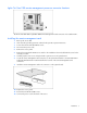
Lights-Out Card 100 remote management processor connector locations The HP ProLiant ML110 G3 Lights-Out 100 Remote Management Card connectors are located at Item 1. Installing the remote management card 1. Back up the server data. 2. Shut down the operating system as outlined in the operation system instructions. 3. Power down the ProLiant ML110 G3 server. 4. Disconnect the power cords. 5. Remove the access panel. 6. Remove the ProLiant ML110 G3 server.
Post-installation procedures 1. Be sure all components are installed according to the "Pre-installation procedures (on page 6)." 2. Be sure you have not left any loose tools or parts inside the server. 3. Reinstall any expansion boards, peripherals, board covers, and system cables previously removed. 4. Reinstall the system covers. 5. Connect all external cables and the AC power cord to the system. 6. Press the power button on the front panel to turn on the server.
Configuration In this section Configuring network access....................................................................................................................... 9 Establishing user accounts ....................................................................................................................... 10 Configuring network access The server is connected to the network using a standard Ethernet cable.
6. Press the down arrow (↓) key to scroll down and enter a valid IP address, subnet mask, and gateway address (press the Tab key to move between address fields). 7. Press the down arrow (↓) key to scroll to the following settings, and set the parameters as needed (the following example shows configuring for remote management processor access using telnet and a Web page): 8.
Using Integrated Lights-Out 100 In this section New features ......................................................................................................................................... 11 SSL overview ......................................................................................................................................... 11 SSH overview ........................................................................................................................................
Lights-Out 100 requires a 2048-bit DSA key stored in PEM (base 64 encoded) format to be located on a TFTP server. For example, use the following instructions using the Win32 OpenSSL, downloaded from the Shining Light Productions website (http://www.slproweb.com/products/Win32OpenSSL.html). Use the following commands in a DOS window to generate the certificate: 1. Download Win32 OpenSSL. 2. Install and setup OpenSSL. 3.
Lights-Out 100 remote management processor can support simultaneous access from two SSH clients. After SSH is connected and authenticated, the command line interface is available. Before using SSH for the first time, perform the one-time setup procedure detailed in the "Importing an SSH key (on page 13)" section. The remote management processor supports: • SSH protocol version 2. • PuTTY 0.54, which is a free version of telnet and SSH protocol available for download on the Internet.
Feature Password authentication Supported for two user accounts Using Secure Shell Using SSH When using a Secure Shell utility to connect to a server for the first time, the utility will prompt you to accept the server's public key, sometimes referred to as a host key. Accepting this key authorizes the utility to store a copy of the public key in its own database.
• Verbs—The supported verbs are: • cd • help • load • reset • set • show • start • stop • exit • version • Target—The default target is the /. The target can be changed by the cd command or by specifying a target on the command line. • Options—The valid options are: • -help/-h • -all/-a • Properties are the attributes of the target that can be modified. • Output—The output syntax is text. The valid Boolean values for any command are yes, no, true, false, y, n, t, and f.
• show displays values of a property or contents of a collection target. For example: /./> show /./ Targets system1/ map1/ Properties Verbs cd version exit show help The first line of information returned by the show command is the current context. In the example, / is the current context. Following the context is a list of sub-targets (Targets) and properties (Properties) applicable to the current context. The verbs (Verbs) section shows what commands are applicable to this context.
//192.168.2.1/pub/firmwareimage.bin transferred to /system1/firmware/fullimage • reset—Causes a target to cycle from enabled to disabled and back to enabled. • set—Sets a property or set of properties to a specific value. • start—Causes a target to change state to a higher run level. • stop—Causes a target to change state to a lower run level. • version—Queries the version of the CLP implementation or other CLP elements.
Logging in to the remote management processor You can log in to the remote management processor through a Web browser ("Logging in through a Web browser" on page 18) or through the CLP ("Logging in through the CLP" on page 18). If you are unsure of your DHCP IP address, refer to the "Configuring network access (on page 9)" section. Logging in through a Web browser 1. Browse to the IP address of the remote management processor to access the login screen. 2. Enter your user name and password.
To access this page from a Web browser, click IPMI PET Configuration on the main menu navigation bar. The PET Destinations section indicates to the remote management processor where to send the PET if it is configured to send the trap to a remote system. This section has up to four entries specifying IP and MAC addresses. The address to use is selected in the Alert Policy Table (shown in the figure).
6. Press the down arrow (↓) key to scroll down to BIOS Serial Console Redirection, and press the Enter key to enter the submenu. 7. Enable the BIOS Serial Console option. 8. Press the down arrow (↓) key to scroll down to Serial Over LAN (SOL), and press the Enter key to enter the submenu. 9. Enable the Serial Over LAN option. 10. Press the Esc key to return to the previous screen, or press the F10 key to save the changes and exit Setup. 11.
Controlling server power remotely Using a Web browser or the CLP, you can remotely operate the power button of a host server. Virtual power support enables you to power on, power off, and power cycle the host server. This virtual power support operates independently of the state of the operating system. Controlling server power from a Web browser 1. Click Virtual Power on the main menu navigation bar. 2. Select the Power Control Option, and click Apply to initiate the Chassis Action. 3.
Monitoring sensors The Monitor Sensors page enables remote monitoring of the current status of major sensors of a target ProLiant ML110 G3 server. The data for this feature can be viewed from the Monitoring Sensors Page through a web browser, or viewed through the BIOS Setup. Viewing sensors data from a Web browser To access this page from a Web browser, click Monitoring Sensors on the main menu navigation bar. This page displays a snapshot of the sensor data.
Accessing the system event log from the CLP 1. Log in to the CLP as described in the "Logging in to the remote management processor (on page 18)" section. 2. Enter cd /system1/log1. 3. Enter show to display the total number of system event records. 4. Enter show record to display the details of a specific record.
3. Reboot the ProLiant ML110 G3 server ("Rebooting the server" on page 25). Configuring the TFTP Server With the virtual floppy features, you can boot the ProLiant ML110 G3 Server with a boot image residing on a remote server. To boot from a virtual floppy from a remote system: 1. Install a TFTP server on a remote system, and ensure that it is running. (TFTP servers are typically included with Linux and are available for other operating systems as well.
Configuring virtual floppy from a Web browser 1. Log in to the remote management processor as described previously in the "Logging in to the remote management processor (on page 18)" section. 2. Click the Virtual Floppy link from the main menu navigation bar. 3. Enter the IP address of the TFTP server that you configured in the previous section. 4. Enter the path to the folder containing the floppy boot image. This path is relative to where the TFTP server program TFTP.exe resides.
this guide. The server continues to reboot to the virtual floppy until the virtual floppy is disabled on the ProLiant ML110 G3 Server as follows: 1. Ensure the target server is configured for network access. Follow the instructions in the "Additional network settings (on page 27)" section of this guide. 2. On the target server, press the F10 key during POST to enter BIOS setup, and navigate to I/O Device Configuration under the Advanced window. Press the Enter key. 3.
Changing the password through the CLP Passwords are case-sensitive and can contain up to 16 characters. To change the user password through the CLP: 1. Log in to the CLP as described in the "Logging in to the remote management processor (on page 18)" section. 2. At the command prompt, enter cd map1/accounts. 3. Select a user by entering cd user1 or cd user2. 4. Enter a new user name by entering set username=. For example: /./map1/accounts/user1/> set username=testuser1 5.
3. Configure the network settings by entering the following: set =. Configurable valid network properties are: • networkaddress—Specifies the IP address for the NIC. This is the dynamic setting. • oemhp_nonvol_networkaddress—Specifies the IP address stored in non-volatile memory. • oemhp_mask—Specifies the subnet mask for NIC. This is the dynamic setting. • oemhp_nonvol_mask—Specifies the subnet mask stored in non-volatile memory.
Initially, there are no entries in the Current PEF Entries section because no PEFs have been defined. When PEF entries are defined, the PEF Control field is active and allows individual entries to be enabled, disabled, and deleted. The Add PEF Entry section contains two main subsections: • Event Offsets are trip points (movements across thresholds) that define what type of sensor event triggers an action. The information in this section varies from sensor to sensor.
• Destination Selector—This field specifies where to send the PET trap from the destinations defined in the PET Destination section.
Acronyms and abbreviations BIOS Basic Input/Output System BMC base management controller CLI Command Line Interface CLP command line protocol DHCP Dynamic Host Configuration Protocol ECC error checking and correcting EMS Emergency Management Services ESD electrostatic discharge HTTP hypertext transfer protocol IP Internet Protocol IPMI Intelligent Platform Management Interface LAN local-area network Acronyms and abbreviations 31
MAC medium access control NIC network interface controller PEF Platform Event Filtering PET Platform Event Trap POST Power-On Self Test RILOE II Remote Insight Lights-Out Edition II SMASH System Management Architecture for Server Hardware SSH Secure Shell SSL Secure Sockets Layer TCP/IP Transmission Control Protocol/Internet Protocol TFTP Trivial File Transfer Protocol URL uniform resource locator USI universal serial interface VSI virtual storage interface Acronyms and abbreviations 32
Index B K browsers 21 kit contents 6 C L CLI (Command Line Interface) 19 CLP (Command Line Protocol), commands 21 CLP overview 14 CLP, commands 14, 15, 17 CLP, using 14 command line options 14, 15, 17 configuration procedures 9 configuration, network 9, 27 configuration, virtual floppy 23 configuring the LOM processor 11 connectors 7 connectors, illustrated 7 logging in 18 logging in, through a browser 18 logging in, through the CLP 18 D DHCP (Dynamic Host Configuration Protocol) 31 E Emergency Man
remote console access, BIOS console text redirection 19 remote console access, text-based console 20 remote management processor, logging in 18 remote management processor, logging in through CLP 18 remote server power, controlling 21 remote server power, controlling using a browser 21 remote server power, controlling using the CLP 21 requirements, SSH 14 S sensor data, viewing 22 server management 5 server, reboot 25 SSH (Secure Shell), requirements 12 SSH (Secure Shell), using 12, 14 SSH, features 12, 13