Hardware Guide 1 Guide to the Printer 2 Installing Options 3 Connecting the Printer 4 Configuration 5 Paper and Other Media 6 Replacing Consumables 7 Adjusting the Printer 8 Troubleshooting 9 Removing Misfed Paper 10 Appendix Read this manual carefully before you use this machine and keep it handy for future reference. For safe and correct use, be sure to read the Safety Information before using the machine.
Trademarks Microsoft, Windows and Windows NT are registered trademarks of Microsoft Corporation in the United States and/or other countries. Adobe®, PostScript®, Acrobat®, PageMaker® and Adobe Type Manager are registered trademarks of Adobe Systems Incorporated. PCL® is a registered trademark of Hewlett-Packard Company. Apple, AppleTalk, EtherTalk, Macintosh, Mac OS, and True Type are trademarks of Apple Computer, Inc., registered in the U.S. and other countries.
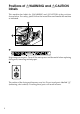
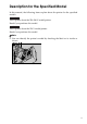
Positions of RWARNING and RCAUTION labels This machine has labels for RWARNING and RCAUTION at the positions shown below. For safety, please follow the instructions and handle the machine as indicated. AQV254S High temperature parts. Turn off the main power and be careful when replacing fusing unit/removing misfed paper. The surface of the fusing unit becomes very hot. Do not touch parts labelled “R” (indicating a hot surface). Touching these parts will result in burns.
Manuals for This Printer For particular functions, see the relevant parts of the manual. ❖ Safety Information Provides information on safe usage of this machine. To avoid injury and prevent damage to the machine, be sure to read this. ❖ Quick Installation Guide Contains procedures for removing the printer from its box, connecting it to a computer, and installing its driver.
How to Read This Manual Symbols This manual uses the following symbols: Indicates important safety notes. Ignoring these notes could result in serious injury or death. Be sure to read these notes. They can be found in the "Safety Information". Indicates important safety notes. Ignoring these notes could result in moderate or minor injury, or damage to the machine or to property. Be sure to read these notes. They can be found in the "Safety Information".
Description for the Specified Model In this manual, the following items explain about the printer for the specified models: This explains about the 220–240 V model printer. Read if you purchase this model. This explains about the 120 V model printer. Read if you purchase this model. Note ❒ You can identify the printer's model by checking the label on its inside as shown.
Installing the Operating Instructions The CD-ROM “Manuals” provided with the printer contains an HTML Operating Instructions Manual in HTML version. Follow this instructions to install it. Important ❒ System Requirements : • Windows 95/98/Me, Windows 2000/XP, Windows Server 2003 or Windows NT4.0. • 800 × 600 or higher monitor resolution. ❒ Web Browsers : • Microsoft Internet Explorer 5.5 SP2 or higher • Firefox 1.0 or higher A Quit all applications currently running.
TABLE OF CONTENTS Trademarks..............................................................................................................i Positions of RWARNING and RCAUTION labels ..............................................ii Manuals for This Printer.......................................................................................iii How to Read This Manual ....................................................................................iv Symbols ...............................................
5. Paper and Other Media Paper and Other Media Supported by This Printer...........................................63 Paper Recommendations....................................................................................67 Loading Paper..........................................................................................................67 Storing Paper ...........................................................................................................67 Types of Paper and Other Media .........
.Appendix Moving and Transporting the Printer...............................................................131 Moving the Printer ..................................................................................................132 Consumables .....................................................................................................133 Toner Cartridge ......................................................................................................133 Maintenance Kit ......................
x
1. Guide to the Printer Exterior: Front View AQV002S 1. Controller Board 7. Output Tray Remove this board when installing the hard disk unit, SDRAM modules, or User Account Enhance unit. Printed output is stacked here with the print side face down. 2. Optional board slots Remove the cover when installing the optional board. Contains keys for printing operation and a panel display that shows the printer status. 3. USB port 9. Front Cover Use a USB cable to connect the printer to the host computer.
Guide to the Printer Exterior: Rear View 1 AQV031S 1. Duplex Unit 5. Lower Vertical Paper Feed Cover Allows you to print onto both sides of the paper. Open this cover when accessing the inside of the printer. 2. Duplex Unit Right Cover 6. Power Cord Open this cover when accessing the inside of the printer. Plug this cord into a wall outlet. 3. Bypass Tray Helps to keep components inside the printer from overheating. Holds up to 50 sheets of plain paper. (80 g/m2, 20 lb.) 4.
Inside Inside 1 AQV005S 1. Fusing Unit 4. Toner Holder When “Replace Maintenance Kit” appears on the panel display, replace this unit. Slide this out when replacing the toner. 2. Transfer Unit When “Replace Maintenance Kit” appears on the panel display, replace this unit. 3. Toner Lock Handle 5. Development Unit When “Replace Maintenance Kit” appears on the panel display, replace this unit. 6. Right Cover Open this cover when accessing the inside of the printer.
Guide to the Printer Control Panel 1 AQV250S 1. {Menu} Key 7. Alert Indicator Press this key to make and check the current printer settings. Blinks or lights up whenever any printer error occurs. A message describing the cause of the error also appears on the panel display. 2. Panel Display Shows the current status of the printer and error messages. 3. {Online} Key Press this key to switch the printer between online and offline. 4.
2. Installing Options Available Options This section describes how to install options. By installing options, you can improve the printer performance and have an expanded variety of features to use. For the specifications of each option, see p.134 “Specifications”. R CAUTION: • Before installing options, the machine should be turned off and unplugged for at least an hour. Components inside the machine become very hot, and can cause a burn if touched.
Installing Options Option Installation Flow Chart Installing multiple options in the following order is recommended: A Attatch the paper feed unit (Paper Feed Unit PB 3020). Attach the paper feed unit to the bottom of the printer. B Take out the controller board from the printer. C Install User Account Enhance Unit (User Account Enhance Unit Type E). 2 Install the module to the User Account Enhance Unit slot of the controller board. D Remove all SDRAM modules before installing the hard disk drive.
Available Options Installing Options Install options in the positions shown in the illustration. ❖ Exterior 2 AQV017S 1. Paper Feed Unit PB 3020 2. Large Capacity Tray RT45 Holds up to 1500 sheets of plain paper. (80 g/m2, 20 lb.) If you want to install the Large Capacity Tray RT45, contact your sales or service representative. 3. Bridge Unit Type 2045 This unit is necessary when using the Finisher. If you want to install the Bridge Unit Type 2045, contact your sales or service representative. 4.
Installing Options ❖ Interior 2 AQV019S 1. Memory Unit Type D 128MB/Memory Unit Type E 256MB (SDRAM module) Install 128 MB or 256 MB SDRAM module into the controller board slot. See p.27 “Attaching Memory Unit Type D 128MB, Memory Unit Type E 256MB (SDRAM Module)”. 2. Optional boards See p.32 “Attaching IEEE 802.11b Interface Unit”. See p.36 “Attaching IEEE 1284 Interface Board Type A”. See p.38 “Attaching Gigabit Ethernet Board”. 3. Optional units See p.41 “Attaching VM Card Type D”. See p.
Available Options Caution when re-installing the controller board This section describes handling the controller board when installing options. If you slide out the controller board to install units, carefully read the instruction to re-install the controller board. Important ❒ The following may occur if the controller board is not properly installed: • all control panel indicators are lit. • no control panel indicators is lit. • the error message appears on the display.
Installing Options Attaching Paper Feed Unit PB 3020 When installing multiple options, install the paper feed unit first. R CAUTION: • Before moving the machine, unplug the power cord from the outlet. If the cord is unplugged abruptly, it could become damaged. Damaged plugs or cords can cause an electrical or fire hazard. 2 • When lifting the machine, use the grips on both sides. The machine could break or cause an injury if dropped.
Attaching Paper Feed Unit PB 3020 B Confirm that the printer is turned off, and the power cord is unplugged from the wall outlet. C Remove the tape that holds the paper feed unit, and then remove the packing material. Do not remove the tape that holds the connector cable inside the connector cover on the back of the paper feed unit in this step. It is removed in the further step.
Installing Options D Align the printer with the two upright pins on the paper feed unit and then lower the printer slowly. 2 AQV007S • The printer should be held by least two people. • When lifting the printer, pull out the grips from the front of the printer. One person should hold the grips on the front and another person should hold the grips on the rear. AQV003S E Push the grips into the printer. Take out the cover inside Tray 2 and attach it between the paper tray and the front cover.
Attaching Paper Feed Unit PB 3020 F Pull the second paper tray (Tray 2) until it stops. After that, lift it slightly, and then pull it out. 2 AQV732S G Pull out the first paper tray (Tray 1) , and take the screwdriver (1) from the tray. AQV222S H Lock the Paper Bank and the printer with the screw. AQV731S Be sure to return the screwdriver to the paper tray after using it.
Installing Options I Open the lower vertical paper feed cover on the right side of the paper feed unit (1). Hang the lock plate hook in the hole inside (2), and then fasten the plate with the knob screw using your fingers. 2 AQV042S J Close the lower vertical paper feed cover. K Open the connector cover (2), remove the tape that holds the connector cable and attach the connector cables (3) as shown in the illustration. AQV009S L Fasten the band as shown until it clicks to secure the cable.
Attaching Paper Feed Unit PB 3020 M Close the connector cover. 2 AQV010S Note ❒ Print a configuration page to confirm that the paper feed unit is properly installed. ❒ If the paper feed unit is not installed properly, reinstall it following this procedure. If you cannot install it properly even after attempting reinstallation, contact your sales or service representative. Reference For printing the configuration page, see “Printing the Test Page”, Quick Installation Guide.
Installing Options Attaching User Account Enhance Unit Type E R CAUTION: • Do not touch the inside of the controller board compartment. Doing so may cause a malfunction or a burn. Important ❒ Before touching the User Account Enhance Unit, ground yourself by touching something metal to discharge any static electricity. Static electricity can damage User Account Enhance Unit. 2 ❒ Do not subject User Account Enhance Unit to physical shocks.
Attaching User Account Enhance Unit Type E D Remove the screws as shown by turning them counterclockwise using the provided screwdriver. 2 AQV500S E Hold the part (1) of the controller board, and then slide it out completely. AQV501S F Place the controller board on a flat surface.
Installing Options G Be sure to install the User Account Enhance Unit as shown. 2 AQU012S H Align the notch of User Account Enhance Unit, and then insert it into the controller board, pressing it down until it clicks into place. AQU013S I Make sure that User Account Enhance Unit is firmly connected to the controller board.
Attaching User Account Enhance Unit Type E J Store the controller board (1) into the printer while gently pressing the cover (2). 2 AQV502S Push in the controller board firmly to align the rails in the printer's compartment. K Fasten all the screws which you removed in step D. AQV503S The printer may malfunction if the controller board is not properly installed. Note ❒ Be sure to return the screwdriver to the paper tray after using it.
Installing Options Attaching Printer Hard Disk Drive Type 8100 R CAUTION: • Do not touch the inside of the controller board compartment. Doing so may cause a machine malfunction or a burn. Important ❒ Before installation, be sure to remove all SDRAM modules from the controller board to prevent from damaging them. 2 ❒ Before touching the hard disk drive, touch something metal to discharge any static electricity. Static electricity can damage the hard disk drive.
Attaching Printer Hard Disk Drive Type 8100 ❖ Power Cable 2 AQV760S ❖ Supplied Screws AQV739S ❖ Protective Sheet AQV740S B Turn off the printer. C Pull out the first paper tray (Tray 1) and take the screwdriver (1) from the tray. Each screw to be removed requires this screwdriver.
Installing Options D Remove the screws as shown by turning them counterclockwise using the provided screwdriver. 2 AQV500S E Hold the part (1) of the controller board, and then slide it out completely. AQV501S F Place the controller board on a flat surface.
Attaching Printer Hard Disk Drive Type 8100 G Remove the default or optional SDRAM module before installing the hard disk drive. Press down the levers on both sides (1) to remove the SDRAM module (2). 2 AQV763S Be sure not to leave any SDRAM module in the slots. Doing so may damage SDRAM modules when installing the hard disk drive. H Place the protective sheet on the controller board as shown, to protect the controller board.
Installing Options J Carefully insert the hard disk drive into the controller board as shown. There is a lip cut into the center of the front end of the hard disk drive's casing. Hook this part over the flange (curled part) in the slot (1) on the controller board, and then align (2) and (3) with the screw holes in the rear edge of the controller board. 2 AQV517S K Fasten the screws clockwise as shown by using the provided screwdriver, to secure the hard disk drive.
Attaching Printer Hard Disk Drive Type 8100 M Connect the blue end of the flat cable to the socket on the controller board. 2 AQV521S When installing an SDRAM module on the controller board, do not store the controller board to the printer, and attach an SDRAM module. N Remove the protective sheet when installing the hard disk drive is completed. AQV737S Be sure to check whether the hard disk drive is completely secured before removing the sheet.
Installing Options P Store the controller board (1) into the printer while gently pressing the cover (2). 2 AQV502S Push in the controller board firmly to align the rails in the printer's compartment. Q Fasten all the screws which you removed in step D. AQV503S The printer may malfunction if the controller board is not properly installed. R When the power is turned on, the hard disk drive will be formatted automatically. Note ❒ Be sure to return the screwdriver to the paper tray after using it.
Attaching Memory Unit Type D 128MB, Memory Unit Type E 256MB (SDRAM Module) Attaching Memory Unit Type D 128MB, Memory Unit Type E 256MB (SDRAM Module) R CAUTION: • Do not touch the inside of the controller board compartment. Doing so may cause a malfunction or a burn. 2 Important ❒ Be sure to install SDRAM modules after installing the hard disk drive. ❒ Before touching the memory unit, ground yourself by touching something metal to discharge any static electricity.
Installing Options C Remove the screws as shown by turning them counterclockwise using the provided screwdriver. 2 AQV500S D Hold the part (1) of the controller board, and then slide it out completely. AQV501S E Place the controller board on a flat surface.
Attaching Memory Unit Type D 128MB, Memory Unit Type E 256MB (SDRAM Module) F Be sure to install the SDRAM module into the slot as shown. 2 AQV560S Two slots are provided for the SDRAM modules. The default SDRAM module is installed in the inner slot. To install an additional memory, attach an additional SDRAM module to the outer slot, or replace the default SDRAM module.
Installing Options I When replacing the default SDRAM module, press down the levers on both sides ( ) to remove the default module ( ). 2 AQV763S Install a new SDRAM module. To increase memory capacity to the maximum of 512 MB, remove the default SDRAM module, and then install two 256 MB SDRAM modules. J Store the controller board (1) into the printer while gently pressing the cover (2). AQV502S Push in the controller board firmly to align the rails in the printer's compartment.
Attaching Memory Unit Type D 128MB, Memory Unit Type E 256MB (SDRAM Module) Note ❒ Be sure to return the provided screwdriver to its original position on the inside of the front cover. ❒ After finishing the installation, you can check the memory unit is properly installed: Print the configuration page from the [List/Test Print] menu. If it is installed properly, the memory capacity will appear under “Total Memory” on the configuration page. ❒ The table below shows the total SDRAM module capacities.
Installing Options Attaching IEEE 802.11b Interface Unit R CAUTION: • Do not touch the inside of the controller board compartment. Doing so may cause a machine malfunction or a burn. Important ❒ For using the IEEE 802.11b interface unit, installing the optional SDRAM module is required. If the optional SDRAM module is not installed, the printer does not detect the unit, and also it does not function because of memory shortage. 2 ❒ Before touching the 802.
Attaching IEEE 802.11b Interface Unit • Antenna ZHBP430E 2 • Antenna Cap AAL888S B Turn off the power, and then unplug the power cable. C Remove the screw by turning it counterclockwise using the provided screwdriver, and then remove the cover of the 802.11b interface board slot. AQV509S The removed cover is not used when installing the interface unit. D Fully insert the 802.11b interface board into the slot.
Installing Options E Tighten the two screws to secure the interface board. 2 AQV523S F Attach the antenna to the card with the label facing down and the uneven side of the antenna facing up. AET096S G With the antenna and the indented end toward you, slowly insert the interface card until it stops.
Attaching IEEE 802.11b Interface Unit H Hold the antenna cap with the cut off corners towards you and fit it over the card. 2 AQV512S Note ❒ After finishing installation, you can check the 802.11b interface unit is properly installed: Print the configuration page from the [List/Test Print] menu. If it is installed properly, “IEEE 802.11b” will appear for “Device Connection” on the configuration page. ❒ If the 802.11b interface unit is not installed properly, reinstall it following this procedure.
Installing Options Attaching IEEE 1284 Interface Board Type A R CAUTION: • Do not touch inside the controller board compartment. Doing so may cause a machine malfunction or a burn. Important ❒ Before handling the 1284 interface board, touch something metal to discharge static electricity. Static electricity thing damage the 1284 interface board. 2 ❒ Do not subject the 1284 interface board to physical shocks.
Attaching IEEE 1284 Interface Board Type A D Fully insert the 1284 interface board into the slot. 2 AQV513S Confirm that the 1284 interface board is firmly connected to the controller board. E Tighten the two screws to secure the 1284 interface board. AQV524S Note ❒ Use the supplied adaptor to make the connection with the computer. ❒ After finishing installation, you can check the 1284 interface board is properly installed: Print the configuration page from the [List/Test Print] menu.
Installing Options Attaching Gigabit Ethernet Board Important ❒ The printer's ethernet and USB ports are not available when the gigabit ethernet board is attached to the printer. Instead, you can use the ethernet port and USB port mounted on the board. 2 ❒ Before handling the gigabit ethernet board, ground yourself by touching something metal to discharge any static electricity. Static electricity can damage the gigabit ethernet board. ❒ Do not subject the gigabit ethernet board to physical shocks.
Attaching Gigabit Ethernet Board C Disconnect the cables from the ethernet port and the USB port of the printer, and cover each port with its protective cap. 2 AQV562S D Remove the screw by turning it counterclockwise using the provided screwdriver, and then remove the cover of the Gigabit ethernet board slot. AQV509S The removed cover is not used when installing the interface unit. E Fully insert the Gigabit ethernet board into the slot.
Installing Options F Tighten the two screws to secure the Gigabit ethernet board. 2 AQV525S Check the Gigabit ethernet board is connected firmly to the controller board. Note ❒ After finishing installation, check the Gigabit ethernet board is installed properly: print the configuration page from the [List/Test Print] menu. If it is installed properly, you will see “Gigabit Ethernet Board” for “Device Connection” on the configuration page.
Attaching VM Card Type D Attaching VM Card Type D Important ❒ For using the VM card, installing the optional SDRAM module is required. If the optional SDRAM module is not installed, the printer does not detect the unit, and also it does not function because of memory shortage. ❒ Protect VM Card Type D from physical shocks. ❒ Using the upper slot is recommended for inserting the unit.
Installing Options Note ❒ Do not touch the VM card while the printer is in use. It may come loose, even if pushed only slightly.
Attaching Data Storage Card Type A Attaching Data Storage Card Type A Important ❒ Protect the data storage card from physical shocks. ❒ Using the upper slot is recommended for inserting the unit. A Check the package contains the following: 2 ❖ Data Storage Card Type A AET104S B Turn off the power, and then unplug the power cable. C Remove the cover of the expansion card slot. AQV504S D Carefully insert the data storage card into the slot, until the card clicks into place.
Installing Options 2 44
3. Connecting the Printer Network Connection Follow the procedure below to connect the printer to the computer through the network. Prepare the hub and other network devices before connecting the 10BASE-T or 100BASE-TX cable to the printer's Ethernet port. Alternatively, the optional gigabit ethernet board, which supports 1000BASE-T, is available. Important ❒ Use shielded Ethernet cable. Unshielded cables create electromagnetic interference that could cause malfunctions.
Connecting the Printer Using the Gigabit Ethernet cable A For using the gigabit ethernet cable, attach one ferrite core at the printer end of the Ethernet cable, and attach the other ferrite core about 10 cm (4 inches) ( ) from this core making a loop as shown. 3 AQV564S B Connect the ethernet cable to the gigabit ethernet board. AQV551S C Connect the other end of the cable to the printer's network, such as a hub.
Network Connection Reading the LED Lamps ❖ For standard ethernet port 3 AQV563S 1. Green: comes on when the printer is properly connected to the network. 2. Yellow: comes on when 100BASETX is being used. It comes off when 10BASE-T is being used. ❖ For gigabit ethernet board AQV563S 1. Yellow: comes on 100BASE-TX is being used. 2. Green: comes on when 10BASE-T is being used. Green and yellow lamps are lit when 1000BASE-T is being used.
Connecting the Printer USB Connection Important ❒ The USB2.0 cable is not supplied. Obtain a cable that is suitable for the computer you are using. ❒ USB connection is possible under Windows Me/2000/XP, Windows Server 2003, Mac OS 9.x, and Mac OS X. ❒ Windows Me supports USB1.1 speeds. ❒ USB connection with Macintosh is only possible via the printer's USB port. 3 A Connect the square-shaped connector of the USB2.0 cable to the USB port.
Parallel Connection Parallel Connection Important ❒ The parallel interface cable is not supplied with the printer. ❒ The printer's parallel connection is a standard bidirectional interface that requires an IEEE 1284-compliant 36-pin parallel cable and host computer parallel port. ❒ Use shielded interface cable. Unshielded cables create electromagnetic interference that could cause malfunctions. ❒ Voltage rating of the computer's parallel port: DC 5 V (max.) 3 A Turn off the printer and computer.
Connecting the Printer 3 50
4. Configuration Ethernet Configuration Make the following network settings according to the network interface you are using. You can use SmartDeviceMonitor for Admin or a Web browser to make IP address-related settings in a TCP/IP-capable environment. Important ❒ Configure the printer for the network using the control panel. ❒ The following table shows the control panel settings and their default values. These items appear in the “Host Interface” menu. Setting Name Value DHCP On IPv4 Address 011.022.
Configuration A Press the {Menu} key. AQV251S B Select [Host Interface] using {T} or {U}, and then press the {q Enter} key. 4 C Select [Network Setup] using {T} or {U}, and then press the {q Enter} key. D Select [Active Protocol] using {T} or {U}, and then press the {q Enter} key. E Select the network protocol using {T} or {U}, and then press the {q Enter} key. F Select [Active] or [Not Active] using {T} or {U}, and then press the {q Enter} key.
Ethernet Configuration G Press the {Escape} key until the screen returns to the [Network Setup] menu. H If you use IPv4, assign the IPv4 address to the printer. Select [IPv4 Settings] using {T} or {U}, and then press the {q Enter} key. 4 To get the IP address for the printer, contact your network administrator. I To specify the IP Address, Select [IPv4 Address] using {T} or {U}, and then press the {q Enter} key. If you use IPv4, assign also Subnet Mask and Gateway Address.
Configuration Using DHCP - Detecting the Network Address Automatically Important ❒ When you use this printer in DHCP environment, select [DHCP] following this procedure. ❒ When [DHCP] is selected, you cannot make settings for the following items: • IP Address • Subnet Mask • Gateway Address ❒ Consult your network administrator for information about making network settings. 4 A Press the {Menu} key. AQV251S B Select [Host Interface] using {T} or {U}, and then press the {q Enter} key.
Ethernet Configuration E Select [DHCP] using {T} or {U}, and then press the {q Enter} key. F Select [On] or [Off]using {T} or {U}, and then press the {q Enter} key. The address will be detected by the printer. The default setting is [Off]. 4 G Press the {Menu} key to return to the initial screen. H Print a configuration page to confirm the settings made. Reference For details about printing the configuration page, see “Printing the Test Page”, Quick Installation Guide.
Configuration A Press the {Menu} key. AQV251S B Select [Host Interface] using {T} or {U}, and then press the {q Enter} key. 4 C Select [Network Setup] using {T} or {U}, and then press the {q Enter} key. D Select [Frame Type (NW)] using {T} or {U}, and then press the {q Enter} key. E Select the frame type using {T} or {U}, and then press the {q Enter} key. F Press the {Menu} key to return to the initial screen. G Print a configuration page to confirm the settings made.
IEEE 802.11b (Wireless LAN) Configuration IEEE 802.11b (Wireless LAN) Configuration Configure the printer to use IEEE 802.11b (Wireless LAN). The following table shows the control panel settings and their default values. These items appear in the [Host Interface] menu. Setting Name Default Value Communication Mode 802.11 Ad hoc Channel • (1-11) 11 • (1-13) 13 Communication Speed Auto SSID blank WEP Not Active 4 Important ❒ For using the IEEE 802.
Configuration B Select [Host Interface] using {T} or {U}, and then press the {q Enter} key. C Select [IEEE 802.11b] using {T} or {U}, and then press the {q Enter} key. D Select [Comm. Mode] using {T} or {U}, and then press the {q Enter} key. 4 E Select the transmission mode of IEEE 802.11b using {T} or {U}, and then press the {q Enter} key. • The factory default is [802.11 Ad hoc]. • To use an IEEE 802.11b card for which the SSID (Network Name) setting is not necessary, select [Ad hoc].
IEEE 802.11b (Wireless LAN) Configuration H Enter the channel using {T} or {U}, and then press the {q Enter} key. I Set [Trans. Speed] in the same way. The factory default is [Auto]. If you need to change the transmitting speed depending on environment you are using, select the appropriate transmitting speed. J Print a configuration page to confirm the settings made. 4 Reference For details about printing the configuration page, see “Printing the Test Page”, Quick Installation Guide.
Configuration D Print a configuration page to confirm the settings made. Reference SSID can also be set using a Web browser. For details, see the Web Image Monitor Help, and “Configuring the Network Interface Board Using Web Browser”, Software Guide. WEP key can also be set using a Web browser. For details, see Web Image Monitor Help. For details about printing the configuration page, see “Printing the Test Page”, Quick Installation Guide.
IEEE 802.11b (Wireless LAN) Configuration D Enter the characters using {T} or {U}, and then press the {q Enter} key. When entering the character, pressing {q Enter} will mask it with an asterisk for security reasons. When using 64 bit WEP, up to 10 characters can be used for hexadecimal and up to five characters for ASCII. When using 128 bit WEP, up to 26 characters can be used for hexadecimal and up to 13 characters for ASCII.
Configuration 4 62
5. Paper and Other Media Paper and Other Media Supported by This Printer This section describes the paper size, feed direction, and the maximum amount of paper that can be loaded into each paper tray in this printer. Note ❒ The following symbols and terminology are used to represent the feed direction.
L 216 × 279 Letter (LT, 11 × 81/2 inches) K 279 × 216 51/2 × 81/2 inches L 140 × 216 Executive (Exec., 71/4 × 101/2 inches) L 184 × 276 Executive (Exec.
Paper and Other Media Supported by This Printer ❖ L 10.2 ” × 14.4 ” A4 L 8.3 ” × 11.7 ” A4 K 11.69 ” × 8.26 ” B5 L 7.17 ” × 10.12 ” B5 K 10.12 ” × 7.17 ” A5 L 5.83 ” × 8.26 ” A5 K 8.26 ” × 5.83 ” A6 K 4.13 ” × 5.63 ” DLT L 11 ” × 17 ” Legal (LG) L 81/2 ” × 14 ” Letter (LT) L 81/2 ” × 11 ” Letter (LT) K 11 ” × 81/2 ” 51/2 × 81/2 inches L 51/2 ” × 81/2 ” Executive (Exec.) L 71/4 ” × 101/2 ” Executive (Exec.
Paper and Other Media • The size is supported, but it should be set as a custom size using the control panel. The supported size may differ depending on the printer language you use. Set as a custom size setting using the control panel. Tray 1/2 or the Paper Feed Unit (Tray 3/4) do not support custom size. The following sizes are supported: • Bypass Tray: approximately 3.94 ”-11.70 ” in width, and 5.83 ”- 23.62 ” in length. • The size is not supported.
Paper Recommendations Paper Recommendations Loading Paper Important ❒ Do not use ink-jet printer paper because it may stick to the fusing unit and cause a paper misfeed. ❒ When printing on OHP transparencies that have a print side, load them with the print side over on the bypass tray. Not taking this precaution may cause them to stick to the fusing unit and cause misfeeds.
Paper and Other Media Types of Paper and Other Media Plain Paper Paper thickness 60 - 90.2 g/m2 (16 - 24 lb.) Printer setup Press the {Menu} key, select [Paper Input] , and then select [Plain Paper] for the selected tray's paper type. Printer driver setup Click [Plain] or [Plain/Recycled] in the [Paper type:] list. Enabled paper feeding tray Any input tray can be used.
Paper Recommendations Label Paper Printer setup Make the following settings using the control panel: • Press the {Menu} key, select [Paper Input], and then select [Labels] for the bypass tray's paper type. Printer driver setup Click [Labels] in the [Paper type:] list. Enabled paper feeding tray This paper type can be printed only from the bypass tray. Make sure paper is not stacked higher than the paper guides inside the bypass tray.
Paper and Other Media • Paper that has already been printed onto, except a preprinted letterhead. Malfunctions are especially likely when using paper printed on by other than a laser printer (e.g. monochrome and color copiers, ink-jet printers, etc.
Loading Paper Loading Paper This describes how to load paper into the paper tray and bypass tray. R CAUTION: • Do not pull out the paper tray forcefully. If you do, the tray might fall and cause an injury. Loading Paper in Tray 1, Tray 2, and the Optional Paper Feed Unit The following example explains loading procedure for the standard paper tray (Tray 1). The same procedure can be used for the optional paper feed unit. Important ❒ Make sure paper is not stacked above the limit mark inside the tray.
Paper and Other Media C While pressing the release lever, adjust the side fences. AQV586S D Adjust the back guide to the new paper size. 5 AQV059S E Align all four sides of the paper stack and load it into the tray with the print side up. AQV139S Confirm that the top of the stack is not higher than the limit mark inside the tray. If there is space between the guides and the stack, move the guides to fit to the stack.
Loading Paper F After loading, make sure that on either side, the paper does not catch (on 1). Push down the paper stack. AQV589S The rear guide is not necessary when 11 × 17 inch paper is loaded in the tray. Put it in the holder in the tray. G Lock the side lever. 5 AQV587S H Adjust the paper size dial to match the size and feed direction of the paper in the paper tray. AQV588S Be sure to set the dial to the correct direction to avoid paper misfeeds.
Paper and Other Media I Slide the tray into the printer gently until it stops. AQV130S Reference For details about paper types supported by the printer, see p.67 “Paper Recommendations”. 5 Loading Paper in the Optional Large Capacity Tray This section describes instructions to load paper in the optional Large Capacity Tray RT45. A Check if the tray release button is lit. If it is not lit, press the button to light it. AQV051S B When the button stops blinking and is lit, open the top cover.
Loading Paper C Load paper with the print side down by pressing the side of the stack to the wall. AQV156S Confirm the top of the stack is not higher than the limit mark inside the tray. D Close the top cover. 5 AQV155S Note ❒ If the printer is in the Energy Saver mode when changing the paper size, Press {q Enter} before printing. This will update the size setting.
Paper and Other Media Setting a Paper Size by Using the Control Panel To load paper whose size cannot be selected automatically, set the paper size on the control panel. Follow the procedure in this section to set the paper size. Important ❒ You cannot set custom paper size for Tray 1/2 or Tray 3/4 (optional paper feed unit). Use the bypass tray if you load paper in custom size, and set bypass tray's paper size using the control panel. A Press the {Menu} key.
Loading Paper F Press the {Menu} key to return to the initial screen. Reference To specify a custom paper size, use only the bypass tray. For details about setting a custom paper size, see p.82 “Specifying Custom Size Paper for the Bypass Tray”. Setting the Paper Size Automatically Important ❒ If you specify the paper size using the control panel, and want to return the settings to load paper size automatically, load paper into the paper tray, and follow this procedure. A Press the {Menu} key.
Paper and Other Media E Select [On] or [Off] using {T} or {U}, and then press the {q Enter} key. F Press the {Menu} key to return to the initial screen. Reference For details about the paper size which is not detected automatically, see p.63 “Paper and Other Media Supported by This Printer”. Specifying a Paper Type for Tray 1/2 and the Optional Paper Feed Unit Improve printer performance by selecting the optimum paper type for the tray.
Loading Paper D Select the tray using {T} or {U}, and then press the {q Enter} key. E Select the paper type using {T} or {U}, and then press the {q Enter} key. F Press the {Menu} key to return to the initial screen. Note ❒ The following paper types cannot be printed on both sides: 5 • Bond Paper, Cardstock Loading Paper in the Bypass Tray Important ❒ Shuffle the paper before loading the stack onto the tray, so multiple sheets are not fed in together.
Paper and Other Media Swing out the extender (1) to support paper sizes larger than A4/letter L. AQV133S B Slide the paper guides outwards, and then load paper until it stops with the print side down. Confirm that the top of the stack is not higher than the limit mark inside the tray. Shuffle the paper before loading the stack onto the tray so multiple sheets are not fed in at one time. 5 C Adjust the paper guides to the paper width.
Loading Paper Specifying Standard Size Paper for the Bypass Tray This describes how to load standard size paper into the bypass tray. A Set the paper size using the control panel. Press the {Menu} key. B Select [Paper Input] using {T} or {U}, and then press the {q Enter} key. C Select [Bypass Tray] using {T} or {U}, and then press the {q Enter} key. 5 D Select the paper size you want to set using {T} or {U}, and then press the {q Enter} key. : : E Press the {Menu} key to return to the initial screen.
Paper and Other Media Specifying Custom Size Paper for the Bypass Tray Important ❒ When loading custom size or special paper, specify the paper size using the control panel and printer driver. ❒ Paper sizes between 148 - 600 mm (5.83-23.62 in.) in length and 100 - 297 mm (3.94-11.70 in.) in width can be loaded in the bypass tray. However, the size range varies depending on a type of printer drivers. For details, see the printer driver Help.
Loading Paper E Enter the horizontal value using {T} or {U}, and then press the {q Enter} key. : : You can set the horizontal value in the following range: 90- 305 mm (3.5412.01 in.) 5 F Enter the vertical value using {T} or {U}, and then press the {q Enter} key. Metric version: : : You can set the vertical value in the following range: 148 mm - 432 mm (5.83 -17.01 in.) By pressing the key, the value increases or decreases by 0.1 mm. By pressing and holding the key, the value varies by 1 mm.
Paper and Other Media Specifying a Paper Type for the Bypass Tray By selecting the paper type you want to load, the printer performs better. You can select from the following paper types: • Plain Paper, Recycled Paper, Special Paper, Color Paper, Letterhead, Prepunched, Labels, Bond Paper, Cardstock, OHP Transparency, Thick Paper Important ❒ Be sure to select the paper type when you load labels, thick paper, envelopes, or OHP transparencies in the bypass tray.
Loading Paper E Select the paper type using {T} or {U}, and then press the {q Enter} key. F Press the {Menu} key to return to the initial screen. Note ❒ The following paper types cannot be printed on both sides: • Special Paper, Labels, Cardstock, Transparency (OHP transparency), Thick Paper, Bond Paper Switching between Paper Trays When paper of the same size is loaded in both the standard tray and the paper feed unit (option), and when [Aut.
Paper and Other Media D Select the tray type you want to use using {T} or {U}, and then press the {q Enter} key. E Press the {Menu} key to return to the initial screen.
6. Replacing Consumables Replacing the Toner Cartridge R WARNING: • Do not incinerate spilled toner or used toner. Toner dust is flammable and might ignite when exposed to an open flame. • Do not store toner, used toner, or toner containers in a place with an open flame. The toner might ignite and cause burns or a fire. R CAUTION: • Keep toner (used or unused) and the toner cartridge out of reach of children.
Replacing Consumables ❒ The actual number of printed pages you get from a particular toner cartridge depends on the type and size of paper you are using, the contents of your print images, and printing environment conditions. ❖ When to replace the toner cartridge If any of the toner cartridge indicators on the initial screen appear to show it is empty, replace the indicated toner cartridge. Replace the toner cartridge if the following message appears on the display: A Open the front cover.
Replacing the Toner Cartridge C While pushing the lever to the right (1), hold the handle and gently slide the toner holder out (2). AQV111S D Press the toner cartridge back to raise its top, and then gently pull it out. 6 AQV746S E Shake the new toner cartridge back and forth about 5 - 6 times as shown.
Replacing Consumables F Remove the black cap of the new toner cartridge by turning it counterclockwise. AQV055S After removing the black cap from the bottle, toner can scatter easily. Do not shake or jar the bottle. G Place the toner cartridge on the toner holder (1), and then pull its head toward you (2) to lock it in place. 6 AQV113S H Slide the toner holder into the printer until it clicks into place, and then push down on the green handle.
Replacing the Toner Cartridge I Close the front cover. AQV105S J Wait while the toner loads. To avoid malfunction, do not turn off the power until “Ready ” appears on the display. Note ❒ Cooperate with the Toner cartridge Recycling Program, whereby are collected used toner cartridges. For details, consult with the dealer where you purchased the printer, or with a sales or service representative.
Replacing Consumables Adding Staples When “Add staples ” appears on the panel display, the staples are almost empty. Follow these steps to replace the staple refill with a new one. Important ❒ After adding the staple refill, staples might not be ejected for the first few times. A Open the front cover of the Finisher SR 3040. 6 AQV700S The cartridge compartment is located at the bottom of the finisher. AQV791S B Hold the green lever while gently pulling out the cartridge.
Adding Staples C Hold both sides of the cartridge, and then pull up the upper unit of it. AQV702S D Take out the empty refill in the arrow direction. 6 AQV703S E Align the arrows on the new refill and the cartridge, and then push in the refill until it clicks.
Replacing Consumables F Gently push down the upper unit into the cartridge. AQV705S G Pull out the ribbon. 6 AQV706S H Hold the green lever while pushing in the cartridge until it clicks. AQV707S I Close the front cover of the finisher.
7. Adjusting the Printer Adjusting the Image Density You can adjust the image density using the control panel if the image density is not appropriate. A Press the {Menu} key. AQV251S B Select [Maintenance] using {T} or {U}, and then press the {q Enter} key. C Select [Image Density] using {T} or {U}, and then press the {q Enter} key. D Specify the image density using {T} or {U}, and then press the {q Enter} key. You can specify the image density in the range of -3 to +3.
Adjusting the Printer Adjusting Tray Registration You can adjust the registration of each tray. The vertical adjustment is used for all trays. Normally, you need not update the registration. But when the optional paper feed unit or the duplex unit is installed, updating is useful in some cases. A Press the {Menu} key. AQV251S B Select [Maintenance] using {T} or {U}, and then press the {q Enter} key. 7 C Select [Registration] using {T} or {U}, and then press the {q Enter} key. D Select [Prt.
Adjusting Tray Registration F Confirm the position of the image on the test sheet, and then adjust the registration value. In this setting, adjust the margins of the test sheet so that they are equal in size. G In the [Registration] menu, Select [Adjustment] using {T} or {U}, and then press the {q Enter} key. 7 H Select the parameter you want to adjust using {T} or {U}, and then press the {q Enter} key. I Set the registration value (mm) using {T} or {U}, and then press the {q Enter} key.
Adjusting the Printer Increase the value to shift the print area in the positive direction, and decrease to shift in the negative direction. AAL708S A : Print Area B : Feed Direction Pressing the {U} or {T} key makes the value increase or decrease by 1.0 mm steps. 7 J Press the {q Enter} key. The display returns to the print area [Adjustment] menu. K Print the test sheet to confirm the adjustment result. L Press the {Menu} key to return to the initial screen.
8. Troubleshooting Error & Status Messages on the Control Panel This section explains what the messages that appear on the control panel mean and what to do when a particular message appears. ❖ Status Messages (in alphabetical order) Message Status Hex Dump Mode In the Hex Dump mode, the printer receives data in hexadecimal format. Turn off the printer after printing, and then turn back on. Suspending... All jobs are suspended. Turn off the printer, and turn it on again to recover.
Troubleshooting ❖ Alert Messages (in alphabetical order) Messages Descriptions and recommended actions Hardware Problem Wireless Board Accessing to the IEEE 802.11b board was possible, but an error has been detected. Check that the board is installed properly. Hardware Problem Wireless Card IEEE 802.11b card access successful, but an error was detected. Check that the card is installed properly. Hardware Problem LCT There is a problem with the paper transfer motor of Large Capacity Tray.
Printer Does Not Print Printer Does Not Print Possible Cause Is the power on? Solutions Confirm that the cable is securely plugged into the power outlet and the printer. Turn on the power. Does the Online indicator stay on? If not, press the {Online} key to light it. Does the Alert indicator stay red? If so, check the error message on the display and take the required action. Is paper loaded? Load paper into the paper tray or onto the bypass tray. See p.71 “Loading Paper”.
Troubleshooting Checking the port connection When the printer is directly connected via the PC cable and the data-in indicator does not flash or light up, the method of checking the port connection is as follows. • For a parallel port connection, port LPT 1 or LPT 2 should be set. • For a USB port connection, port USB00 (n) *1 should be set. *1 (n) is the number of printers connected. Windows 95/98/Me A Click [Start], point to [Settings] and then click [Printers].
Printer Does Not Print Windows XP Home Edition A Access the [Control Panel] window from [Start] on the taskbar. B Click [Printers and Other Hardware]. C Click [Printers and Faxes]. D Click to select the icon of the printer. Next, on the [File] menu, click [Properties]. E Click the [Port] tab. F Check the [Print to the following port(s).] box to confirm that the correct port is selected. Windows NT 4.0 A Click [Start], point to [Settings] and then click [Printers].
Troubleshooting Other Printing Problems Status Toner smears appear on the print side of the page. Possible Causes, Descriptions, and Solutions The paper setting may not be correct. For example, although you are using thick paper, the setting for thick paper may not be set. • Check the paper settings. See p.68 “Types of Paper and Other Media”. • Check the printer driver's paper settings. See the printer driver Help. Confirm that the paper is not curled or bent. Envelopes can be curled easily.
Other Printing Problems Status Paper gets wrinkles. Possible Causes, Descriptions, and Solutions • Paper is damp. Use paper that has been stored properly. See p.63 “Paper and Other Media”. • Paper is too thin. See p.63 “Paper and Other Media”. • There may be a gap between the guides and the paper in the paper tray. Make sure there are no gaps. See p.71 “Loading Paper”. • The fusing unit is deteriorated or damaged. Replace the unit. For replacing the unit, Maintenance Kit (optional) is required.
Troubleshooting Status Images are cut off, or excess pages are printed. Possible Causes, Descriptions, and Solutions If you are using paper smaller than the paper size selected in the application, use the same size paper as that selected in the application. If you cannot load paper of the correct size, use the reduction function to reduce the image, and then print. See the printer driver Help.
Other Printing Problems Status Possible Causes, Descriptions, and Solutions The backs of printed sheets are blemished. • When removing a jammed sheet, the inside of the printer may have become dirtied. Print several sheets until they come out clean. • If document size is larger than paper size, e.g. A4 document on B5 paper, the back of the next printed sheet may be dirtied. If rubbed with your finger, it smears out. The setting of the paper may not be correct.
Troubleshooting Status Possible Causes, Descriptions, and Solutions The paper size appears on the control panel and printing is not performed with PDF Direct Print. When using PDF Direct Print, printout requires paper set within the PDF file. When a message indicating a paper size appears, either place the indicated size in the paper tray, or perform Form Feed. Also, if [Sub Paper Size] in the System Menu is set to [Auto], printing is performed assuming letter size and A4 size to be the same size.
Additional Troubleshooting Additional Troubleshooting Problems Solutions Strange noise is heard. If a supply was recently replaced or an option attached in the area the strange noise is coming from, check the supply or option is properly attached. If the strange noise persists, contact your sales or service representative. IEEE 802.11b Interface Unit is not detected by the printer, even if it is installed properly.
Troubleshooting Problems Solutions Alert Occurrence and Alert Resolving are set for sending email, but while no Alert Occurrence mail is received, Alert-resolved e-mail is received. Alert-notification e-mail is not sent if the problem is resolved before sending. However, an Alert-resolved e-mail is sent. Alert-notification level was If an Alert-notification e-mail, set with the earlier notification changed, and e-mail stopped ar- level, arrives, later e-mail will not be sent, even if the notifiriving.
Removing Jammed Staples Removing Jammed Staples If staples do not eject properly, they might be jammed. Important ❒ Staples might be jammed because of curled paper. In this case, try turning the paper over in the tray. ❒ After removing the jammed staples, staples might not be ejected for the first few times. A Open the front cover of the Finisher SR 3040. AQV700S The cartridge compartment is located at the bottom of the finisher.
Troubleshooting C Pull up the cartridge's knob. AQV708S D Take out all staples slid from the cartridge. AQV709S E Pull down the cartridge's knob until it clicks.
Removing Jammed Staples F Hold the green lever while pushing in the cartridge until it clicks. AQV711S G Close the front cover of the finisher.
Troubleshooting Removing Punch Waste While “Empty Punch Receptacle” is displayed, you cannot use the Punch function. A Open the front cover of the finisher. A QV780S B Pull out the punch waste box, and then remove punch waste. 8 AQV781S C Reinstall the punch waste box. AQV782S If you do not, “Empty Punch Receptacle” is still displayed. D Close the front cover of the finisher. “Empty Punch Receptacle” disappears.
Removing Punch Waste Note ❒ If the message is still displayed, reinstall the punch waste box. ❒ The message “Empty Punch Receptacle” may appear even when the punch waste box is not yet full. If this happens, the position of the punch waste box (indicated by the arrow as shown) may be blocked by punch waste. Remove the punch waste.
Troubleshooting 8 116
9. Removing Misfed Paper Removing Misfed Paper An error message appears if a paper misfeed occurs. The error message gives the location of the misfeed. R CAUTION: • The inside of the machine becomes very hot. Do not touch the parts with a “v” label (means hot surface). Touching a part with a “v” label (means hot surface) could result in a burn. R CAUTION: • When pulling the paper tray out, be careful not to pull it strongly. If you do, the tray might fall and cause an injury.
Removing Misfed Paper When “Remove Misfeed A,Y:Paper Tray” Appears When the “Remove Misfeed A,Y:Paper Tray” message appears, do the followings: A Open the Bypass Tray (1), and then open the Duplex Unit by pushing the catch upwards (2). AQV223S B Open the right cover by pushing the catch upwards. AQV224S If the optional Large Capacity Tray RT45 is equipped with your printer, pull the lever (1) to extend the connecting unit (2).
Removing Misfed Paper C Open the lower vertical paper feed cover. AQV066S D Remove misfed paper slowly. AQV067S E Close the lower vertical paper feed cover. F Open the upper vertical paper feed cover. 9 AQV063S If your printer is equipped with the optional Large Capacity Tray RT45, the upper vertical paper feed cover is removed.
Removing Misfed Paper G Turn the blue knob A1 downwards. A1 AQV064S H While lifting the blue lever A2 in the right cover (1), remove the misfed paper (2). 1 A2 2 AQV119S I Open the Bypass Tray, and then remove the misfed paper.
Removing Misfed Paper When “Remove Misfeed B,C,D:Inter.Path” Appears When the “Remove Misfeed B,C,D:Inter.Path” message appears, do the followings: A Open the output feeder cover of the Bridge Unit (1), and then remove the misfed paper (2). 1 2 AQV123S B Open the Bypass Tray (1), and then open the Duplex Unit by pushing the catch upwards (2). AQV223S 9 C Open the right cover by pushing the catch upwards.
Removing Misfed Paper D Open the front cover. AQV201S E Remove the misfed paper by turning the blue knob C as shown in the illustration. If you turn the blue knob C clockwise (1) , the misfed paper comes out to the output tray (2). AQV115S If you turn the blue knob C counterclockwise (1), remove the misfed paper from inside the right cover (2).
Removing Misfed Paper F If you can see the paper from the right of the printer, remove it. AQV121S G Turn the blue knob B counterclockwise (1), and then remove the misfed paper from inside the right cover (2). B AQV120S H Close the covers in the following order: • • • • • The right cover The Duplex Unit The Bypass Tray The front cover The output feeder cover 9 I Open the covers of the Bridge Unit (1), and then remove the misfed paper (2). 1 2 AQV124S J Close the cover of the Bridge Unit.
Removing Misfed Paper When “Remove Misfeed R:Finisher” Appears When the “Remove Misfeed R:Finisher” message appears, do the followings: A Open the upper cover, and then remove misfed paper. AQV577S B If you cannot remove misfed paper, open the slide cover and remove the misfed paper. AQV578S 9 C Open the front cover.
Removing Misfed Paper D Hold up the lever R1, and remove the misfed paper. AQV580S E Hold down the lever R2, and remove the misfed paper. AQV581S F If you cannot remove misfed paper, hold down the lever R3 and remove the misfed paper.
Removing Misfed Paper G Hold down the lever R4, and remove the misfed paper. AQV583S H Pull the lever R5 and remove the misfed paper. AQV584S I When removing the misfed paper completed, close the front cover of the finisher.
Removing Misfed Paper When “Remove Misfeed U:LCT” Appears When the “Remove Misfeed U:LCT” message appears, do the followings: A Open the top cover of the Large Capacity Tray RT45. AQV154S B Remove the misfed paper. AQV068S C If you cannot remove the misfed paper in the previous step, close the top 9 cover of the Large Capacity Tray RT45 and pull the lever (1) to extend the connecting unit (2).
Removing Misfed Paper D Remove the misfed paper from the left side of the Large Capacity Tray RT45. AQV069S E Slide the Large Capacity Tray RT45 forward to connect it to the printer.
Removing Misfed Paper When “Remove Misfeed Z:Duplex Unit” Appears When the “Remove Misfeed Z:Duplex Unit” message appears, do the followings: A Open the Bypass Tray and the Duplex Unit right cover, and then remove the misfed paper. AQV122S B Close the Duplex Unit right cover. C Open the Duplex Unit by pushing the catch upwards (1). 9 AQV146S D Open the cover Z to the left (1), and then remove the misfed paper (2).
Removing Misfed Paper 9 130
10. Appendix Moving and Transporting the Printer R CAUTION: • When moving the machine, each person should hold the handles that are located on opposite sides, and then lift it slowly. Lifting it carelessly or dropping it may cause an injury. • When you move the printer, remember to unplug the power cord from the wall outlet to avoid a fire or an electric shock. • When you pull out the plug from the socket, grip the plug, not the cord, to avoid damaging the cord and causing a fire or an electric shock.
Appendix Moving the Printer R CAUTION: • When lifting the machine, use the inset grips on both sides. Otherwise the printer could break or cause an injury if dropped. • Before moving the machine, unplug the power cord from the wall outlet. If the cord is unplugged abruptly, it could become damaged. Damaged plugs or cords can cause an electrical or fire hazard. Moving the printer in a short distance A Be sure to check the following points: • The power switch is turned off.
Consumables Consumables Important ❒ Our products are engineered to meet the highest standards of quality and functionality. When purchasing expendable supplies, we recommend using only those specified by an authorized dealer. Toner Cartridge Toner cartridge Black *1 Average printable number of pages per bottle *1 30,000 pages A4/letter 5% test chart, 2 pages/job Note ❒ If toner cartridges are not changed when necessary, printing will become impossible.
Appendix Specifications Mainframe ❖ Configuration: Desktop ❖ Print Process: Laser beam scanning & Electrophotographic printing Dualcomponent development ❖ First Print Speed: 6 sec or less (A4L/8 1/2 × 11L) Note ❒ If the printer has not been used for a while, there may be a short delay before the first page starts printing. ❖ Printing Speed: • Maximum 45 pages per minute (A4L/8 1/2 × 11L), one-sided/duplex Printing speed may vary depending on the setting up environment.
Specifications ❖ Power Source: • 220 - 240 V, 8 A or more, 50/60 Hz • 120 V, 12 A or more, 60 Hz ❖ Power Consumption: • Printing 1,450 W or less (No power is used during power off.) Energy Saver 6 W or less Printing 1,400 W or less (No power is used during power off.) Energy Saver 6 W or less • ❖ Warm-up Time: Less than 22 seconds (20 °C/68 °F) *1 Less than 15 seconds from Energy Saver mode (20 °C/68 °F) *1 *1 When no error is occurred.
Appendix ❖ Noise Emission *1 : Sound Power Level Mainframe only Stand-by 46.5 dB (A) During Printing 68 dB (A) Sound Pressure level *2 Mainframe only Stand-by 40.5 dB (A) During Printing 62 dB (A) *1 *2 The preceding measurements made in accordance with ISO7779 are actual values. Measured at the position of a bystander. ❖ Memory: Standard 128/256 MB, up to 512 MB (with the optional Memory Unit) ❖ Interface: Standard: • Ethernet (10/100 Base-TX) • USB2.
Specifications Options Paper Feed Unit PB 3020 ❖ Paper size: See p.63 “Paper and Other Media Supported by This Printer”. ❖ Dimensions (W × D × H): 670 × 640 × 260 mm (26.4 ” × 25.2 ” × 10.3 ”) ❖ Paper weight: See p.63 “Paper and Other Media Supported by This Printer”. ❖ Weight: Approx. 25 kg (55.2 lb.) Note ❒ Specifications are subject to change without notice. Large Capacity Tray RT45 ❖ Paper size: See p.63 “Paper and Other Media Supported by This Printer”. ❖ Paper weight: See p.
Appendix Finisher SR 3040 Shift Tray 1: ❖ Paper size: A3L, B4 JISL, A4KL, B5 JISKL, A5KL, B6 JISL, A6L, 11 ” × 17 ”L, 81/2 ” × 14 ”L, 81/2 ” × 11 ”KL, 51/2 ” × 81/2 ”KL ❖ Paper weight: 52 – 163 g/m2 (14 – 43 lb) ❖ Stack capacity: • 500 sheets (A4KL, B5 JISKL, A5K, 81/2 ” × 11 ”KL) (80 g/m2, 20 lb.) • 250 sheets (A3L, B4 JISL, 81/2 ” × 14 ”L, 11 ” × 17 ”L) (80 g/m2, 20 lb.) • 100 sheets (A5L, 51/2 ” × 81/2 ”KL) (80 g/m2, 20 lb.
Specifications ❖ Staple paper weight: 64 – 90 g/m2 (17 – 24 lb.) ❖ Staple position: • 1 staple – 3 positions • 2 staples – 1 position ❖ Power consumption: Less than 60 W (power is supplied from the main unit) ❖ Dimensions (W × D × H): 680 × 620 × 1030 mm (28.8 ” × 24.5 ”× 40.6 ”) ❖ Weight: Without the punch unit: Approx. 53 kg (116.9 lb.) With the punch unit: Approx. 55 kg (121.3 lb.) Punch Kit Type 1045 This is the optional unit for the Finisher SR 3040.
Appendix Printer Hard Disk Drive Type 8100 ❖ Storage Capacity (Formatted): 40 GB ❖ Specifications: • Spooling print data to collate • Storing/Spooling Sample Print/Locked Print/Hold Print/Stored Print data • Storing PostScript fonts • Storing log data Note ❒ You can install PostScript fonts with this optional hard disk drive. With Mac OS, types of fonts supported are PostScript Type 1 and PostScript Type 2. To download them, use Printer Utility for Mac.
Specifications ❖ Data Transfer Speed: Auto select from below speed 1 Mbps, 2 Mbps, 5.5 Mbps, 11 Mbps ❖ Frequency Range: • Inch version: 2412-2462 MHz (1-11 channels) • Metric version: 2412-2472 MHz (1-13 channels) ❖ Transmittable Distance: 1 Mbps 400 m *1 2 Mbps 270 m *1 5.5 Mbps 200 m *1 11 Mbps 140 m *1 *1 These figures are a guideline for outdoor use. In general, the transmittable distance indoors is 10-100 m, depending on the environment.
Appendix ❖ Transmittable Distance: 1 Mbps 400 m *1 2 Mbps 270 m *1 5.5 Mbps 200 m *1 11 Mbps 140 m *1 *1 These figures are a guideline for outdoor use. In general, the transmittable distance indoors is 10-100 m, depending on the environment. ❖ Transmission Mode: ad hoc mode and infrastructure mode IEEE 1284 Interface Board Type A ❖ Transmission Spec.
INDEX F 1284 Interface Board, 5, 36, 49 802.11b Interface Unit, 5, 32, 57 Fusing Unit, 133 G A Additional Troubleshooting, 109 Adhesive labels, 69 Adjusting image density, 95 tray registration, 96 Alert Indicator, 4 Appendix, 131 Attaching 1284 Interface Board, 36 Attaching 802.
M Maintenance Kit, 133 Memory Unit, 140 Memory Unit (SDRAM module), 5, 27 Menu Key, 4 Messages, 99 Moving and Transporting the Printer, 131 N Network, 45, 51 O OHP transparencies, 69 Option Installation Flow Chart, 6 Option List, 5 Options, 137 Other Printing Problems, 104 P Panel Display, 4 Paper and Other Media, 63 Paper Feed Unit PB 3020, 5, 10, 137 Paper not supported, 69 Paper Recommendations, 67 Plain Paper, 68 Power Indicator, 4 Print Area, 70 Printer Does Not Print, 101 Printer Hard Disk Drive Ty
Copyright © 2006
Hardware Guide Model No.