Hardware Reference Guide HP EliteOne 1000 G2 All-in-One Business PCs
© Copyright 2018 HP Development Company, L.P. Thunderbolt and the Thunderbolt logo are trademarks of Intel Corporation or its subsidiaries in the U.S. and/or other countries. Windows is either a trademark or registered trademark of Microsoft Corporation in the United States and/or other countries. The information contained herein is subject to change without notice. The only warranties for HP products and services are set forth in the express warranty statements accompanying such products and services.
About This Book This guide provides basic information for upgrading this computer model. WARNING! Indicates a hazardous situation that, if not avoided, could result in death or serious injury. CAUTION: Indicates a hazardous situation that, if not avoided, could result in minor or moderate injury. IMPORTANT: Indicates information considered important but not hazard-related (for example, messages related to property damage).
iv About This Book
Table of contents 1 Product features ........................................................................................................................................... 1 Overview ................................................................................................................................................................ 1 Base unit top components .....................................................................................................................................
Replacing or installing a webcam ........................................................................................................................ 28 Appendix A Electrostatic discharge .................................................................................................................. 31 Preventing electrostatic damage ........................................................................................................................ 31 Grounding methods ............................
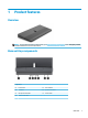
1 Product features Overview NOTE: For the latest manuals on this product, go to http://www.hp.com/support. Select Find your product, and then follow the on-screen instructions.
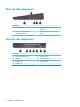
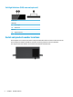
Base unit side components Components (1) Fingerprint reader (3) USB Type-C Thunderbolt™ port with HP Sleep and Charge (2) Audio-out (headphone)/Audio-in (microphone) combo jack (4) USB SuperSpeed port with HP Sleep and Charge Base unit rear components Components 2 (1) USB SuperSpeed Plus ports (4) (5) Power connector (2) HDMI port (6) RJ-45 (network) jack (3) DisplayPort Out (7) Security cable slot (4) DisplayPort In Chapter 1 Product features
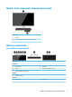
Monitor front components (select products only) Components (1) Webcam (2) On-screen display buttons (for adjusting the screen) Webcam components Infrared (IR) webcam (optional) Components Front View (1) Webcam light (4) IR webcam (2) IR light (5) Rear webcam adjustment wheel (3) Full High Definition (FHD) webcam (8) FHD webcam Top view (6) Digital microphones Rear view (7) Webcam light Monitor front components (select products only) 3
Full High Definition (FHD) webcam (optional) Components Front view (1) Webcam light (2) FHD webcam Top view (3) Digital microphones Serial and product number locations Each computer has a unique serial number and product ID number that are located on the exterior of the device. Keep these numbers available for use when contacting customer service for assistance. The computer base unit numbers are located on the underside of the base unit.
2 Setup Installing the monitor head A monitor head can be installed in the standalone computer base. The monitor head can then be removed and replaced with a different monitor. 1. Remove all removable media, such as USB flash drives, from the computer. 2. Turn off the computer properly through the operating system, and turn off any external devices. 3. Disconnect the power cord from the AC outlet and disconnect any external devices.
6 5. Disconnect the two monitor cables attached to the system board by squeezing firmly inward on the two ends of the cable connectors (1) and pulling the cable connectors up and off the system board (2). 6. To remove the rear access cover from the computer, press the two release buttons on the rear of the base unit (1), and at the same time rotate the rear of the cover up (2). Then, slide the cover back to remove it from the computer (3). 7. Turn the cover over.
8. Loosen the two captive screws at the base of the monitor head’s neck (1). While holding onto the bottom of the monitor head from the front with one hand, slide the monitor head back with your other hand to clear it from the small metal retention tab, and then lift the monitor off the base (2). IMPORTANT: The monitor head is heavy. Make sure you are holding the monitor head firmly when removing it to prevent the monitor head from falling over and being damaged. 9.
10. Connect the two monitor cables to the system board connectors. 11. To replace the rear access cover, slide the tabs on the front of the rear cover into the slots on the rear of the front cover (1), and then press the rear of the rear cover down (2). NOTE: Be sure that all cables are properly routed to prevent damage when the cover is replaced. 12. Reconnect the power cord and any external devices, and then turn on the computer.
Enabling the monitor head detection warning This warning is monitored if the monitor head cables are not fully connected. HP recommends ensuring that this warning is enabled on systems with an installed monitor head. 1. Turn on or restart the computer, and when the HP logo appears, press f10 to enter Computer Setup. 2. Select Advanced, and then select Built-In Devices. 3. Select Allow No Panel configuration. 4. Select Main, and then Save Changes and Exit to save your settings.
Adjusting the monitor head position Tilt the monitor head to set it to a comfortable eye level. NOTE: The 23.8-inch, 27-inch, and 34-inch monitor heads tilt back. Only the 23.8-inch and 27-inch monitor heads tilt forward. The 34-inch monitor head does not tilt forward. Adjust the height of the monitor head to set it to a comfortable eye level. NOTE: Only the 23.8-inch monitor head has height adjustment. The 27-inch and 34-inch monitor heads do not have height adjustment.
Connecting a secondary monitor The DisplayPort and HDMI ports on the rear of the computer allow you to connect secondary monitors to the computer. You can connect up to two monitors in one of the following configurations: ● Two monitors daisy-chained to the DisplayPort ● One monitor connected to the DisplayPort and one to the HDMI port If you are adding a monitor that has a DisplayPort or an HDMI port, then no video adapter is required.
Using the webcam You can use the webcam on the monitor in the following ways: ● Stream online video conferences ● Send and receive Instant messages ● Schedule meetings ● Maintain security over conversations Webcam operation ● To raise the webcam, press it down to unlock it. ● To close the webcam, press it down until it locks. Setting up Windows Hello If the Windows® 10 operating system is installed on your computer, follow these steps to set up Windows Hello facial recognition: 12 1.
Synchronizing the optional wireless keyboard and mouse The wireless keyboard and mouse are optional components. The mouse and keyboard are synchronized at the factory. If the mouse and keyboard are not synchronized, then follow the procedure below to manually resynchronize the pair. 1. Insert the transceiver into a USB port on the computer. 2. Place the keyboard within 30 cm of the transceiver. Press the connect button on the bottom of the keyboard, and then press a key on the keyboard. 3.
3 Hardware repair and upgrade Warnings and cautions Before performing upgrades be sure to carefully read all of the applicable instructions, cautions, and warnings in this guide. WARNING! To reduce the risk of personal injury from electrical shock, hot surfaces, or fire: Disconnect the power cord from the AC outlet before removing the enclosure. Energized parts are inside. Allow the internal system components to cool before you touch them.
Removing and replacing the base unit access covers The base unit access covers must be removed to access internal computer components. 1. Remove all removable media, such as USB flash drives, from the computer. 2. Turn off the computer properly through the operating system, and turn off any external devices. 3. Disconnect the power cord from the AC outlet and disconnect any external devices.
b. Rotate the left side of the cover away from the base unit while being careful not to disconnect the cable attached to the right side of the cover. You can now service the computer components. To replace the access covers: 1. 16 To replace the front access cover, align the cover with the monitor head and then press the cover straight down onto the base unit so that the cover snaps in place.
2. To replace the rear access cover, slide tabs on the front of the rear cover into the slots on the rear of the front cover (1), and then press the rear of the rear cover down (2). NOTE: Be sure that all cables are properly routed to prevent damage when the cover is replaced. 3. Reconnect the power cord and any external devices, and then turn on the computer. Removing and replacing the monitor head The monitor head can be removed and replaced with a different monitor.
18 4. To remove the rear access cover, press the two release buttons on the rear of the base unit (1), and at the same time rotate the rear of the cover up (2). Then slide the cover back to remove it from the base (3). 5. Disconnect the two monitor cables attached to the system board by firmly squeezing inward on the two ends of the cable connectors (1) and pulling the cable connectors up and off the system board (2).
6. Loosen the two captive screws at the base of the monitor head’s neck (1). While holding onto the bottom of the monitor head from the front with one hand, slide the monitor head back with your other hand to clear it from the small metal retention tab, and then lift the monitor off the base (2). IMPORTANT: The monitor head is heavy. Make sure you are holding the monitor head firmly when removing it to prevent the monitor head from falling over and being damaged. 7.
8. Connect the two monitor cables to the system board connectors. 9. To replace the rear access cover, slide tabs on the front of the rear cover into the slots on the rear of the front cover (1), and then press the rear of the rear cover down (2). NOTE: Be sure that all cables are properly routed to prevent damage when the cover is replaced. 10. Reconnect the power cord and any external devices, and then turn on the computer.
Locating internal components Components (1) Hard drive (3) RTC battery (2) M.2 SSD (under the fan) (4) Memory modules Removing and installing memory The memory slots on the system board can be populated with up to two industry-standard small outline dual inline memory modules (SODIMMs). These memory slots are populated with at least one preinstalled memory module.
Populating memory modules Refer to the following table to identify the memory module channel locations. Location System board label Channel Lower Socket SODIMM1 Channel B Upper Socket SODIMM3 Channel A The system will automatically operate in single channel mode, dual channel mode, or flex mode, depending on how the memory modules are installed. ● The system will operate in single channel mode if the memory module slots are populated in one channel only.
6. To remove a memory module, press outward on the two latches on each side of the memory module (1), and then pull the memory module out of the socket (2). 7. To install a memory module, slide the memory module into the socket at approximately a 30° angle (1), and then press the memory module down (2) so that the latches lock it in place. NOTE: A memory module can be installed in only one way. Match the notch on the module with the tab on the memory slot. 8.
IMPORTANT: Before replacing the battery, it is important to back up the computer CMOS settings. When the battery is removed or replaced, the CMOS settings will be cleared. Static electricity can damage the electronic components of the computer or optional equipment. Before beginning these procedures, ensure that you are discharged of static electricity by briefly touching a grounded metal object. NOTE: The lifetime of the lithium battery can be extended by plugging the computer into a live AC outlet.
Replacing the hard drive To locate the hard drive on the system board, see Locating internal components on page 21. 1. Remove all removable media, such as USB flash drives, from the computer. 2. Turn off the computer properly through the operating system, and turn off any external devices. 3. Disconnect the power cord from the AC outlet and disconnect any external devices.
7. Install the four mounting screws that were removed from the old drive in the sides of the new hard drive. 8. Connect the cable to the rear of the hard drive (1). Then align the mounting screws on the drive with the J-slots on the sides of the drive bay and press the drive into the drive bay. And then slide the drive forward until it locks in place (2). 9. Replace the base unit front and rear access panels. See Removing and replacing the base unit access covers on page 15. 10.
IMPORTANT: Regardless of the power-on state, voltage is always present on the system board as long as the system is plugged into an active AC outlet. You must disconnect the power cord and wait approximately 30 seconds for the power to drain to avoid damage to the internal components of the computer. 4. Remove the base unit rear and front access panels. See Removing and replacing the base unit access covers on page 15. 5. The M.
7. To install an M.2 SSD, slide the connector end of the SSD into the system board connector (1), press the other end of the SSD down (2), and then secure the SSD to the system board with the screw (3). 8. Replace the fan by pressing it down onto the system board posts. 9. Replace the base unit front and rear access panels. See Removing and replacing the base unit access covers on page 15. 10. Reconnect the power cord and any external devices, and then turn on the computer.
IMPORTANT: Regardless of the power-on state, voltage is always present on the system board as long as the system is plugged into an active AC outlet. You must disconnect the power cord and wait approximately 30 seconds for the power to drain to avoid damage to the internal components of the computer. 4. Insert a paper clip into the release holes on each side of the webcam (1) to disengage the internal latches, and then pull the webcam out of the monitor head (2). 5.
30 4. Grasp the top of the rear panel on the monitor head at the webcam slot and pull the panel off the monitor head at the connection points (1), and then slide the rear cover down the neck of the stand (2). 5. Remove the screws from the webcam blank (1), and then slide the blank back to remove it from the monitor head (2). 6. Snap the rear panel onto the monitor head. 7.
A Electrostatic discharge A discharge of static electricity from a finger or other conductor may damage system boards or other staticsensitive devices. This type of damage may reduce the life expectancy of the device. Preventing electrostatic damage To prevent electrostatic damage, observe the following precautions: ● Avoid hand contact by transporting and storing products in static-safe containers. ● Keep electrostatic-sensitive parts in their containers until they arrive at static-free workstations.
B Computer operating guidelines, routine care, and shipping preparation Computer operating guidelines and routine care Follow these guidelines to properly set up and care for the computer and monitor: ● Keep the computer away from excessive moisture, direct sunlight, and extremes of heat and cold. ● Operate the computer on a sturdy, level surface. Leave a 10.2 cm (4 in) clearance on all vented sides of the computer and above the monitor to permit the required airflow.
Shipping preparation Follow these suggestions when preparing to ship the computer: 1. Back up the hard drive files to an external storage device. Be sure that the backup media is not exposed to electrical or magnetic impulses while stored or in transit. NOTE: The hard drive locks automatically when the system power is turned off. 2. Remove and store all removable media. 3. Turn off the computer and external devices. 4. Disconnect the power cord from the AC outlet, and then from the computer. 5.
C Accessibility HP designs, produces, and markets products and services that can be used by everyone, including people with disabilities, either on a stand-alone basis or with appropriate assistive devices. Supported assistive technologies HP products support a wide variety of operating system assistive technologies and can be configured to work with additional assistive technologies. Use the Search feature on your device to locate more information about assistive features.
Index A access panels removal 15 replacement 15 accessibility 34 additional information M M.