
HP EliteBook 820 G2 Notebook PC and HP EliteBook 720 G2 Notebook PC - Maintenance and Service Guide

5 Removal and replacement procedures for
Customer Self-Repair parts
NOTE: The Customer Self-Repair program is not available in all locations. Installing a part not supported by
the Customer Self-Repair program may void your warranty. Check your warranty to determine if Customer
Self-Repair is supported in your location.
NOTE: HP continually improves and changes product parts. For complete and current information on
supported parts for your computer, go to http://partsurfer.hp.com, select your country or region, and then
follow the on-screen instructions.
Component replacement procedures
This chapter provides removal and replacement procedures for Authorized Service Provider only parts.
There are as many as 15 screws that must be removed, replaced, and/or loosened when servicing the
computer. Make special note of each screw size and location during removal and replacement.
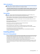
Service cover
NOTE: The service cover spare part kit includes rubber feet.
Description Spare part number
Service cover for use in 820 G2 models 781836-001
Service cover for use in 720 G2 models 790080-001
Service cover for use only on RCTO models 797517-001
Before removing the disassembling the computer, follow these steps:
1. Turn o the computer. If you are unsure whether the computer is o or in Hibernation, turn the
computer on, and then shut it down through the operating system.
2. Disconnect the power from the computer by unplugging the power cord from the computer.
3. Disconnect all external devices from the computer.
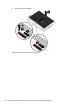
Remove the service cover:
1. Turn the computer upside down, with the rear toward you.
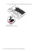
2. Slide the service cover release latch (1) to gain access to the service cover security screw.
3. Remove the Phillips PM2.0×4.5 security screw (2) (if present).
NOTE: The service cover includes a threaded receptacle for storing the security screw.
4. Slide the service cover release latch a second time (3) to release the service cover.
5. Release the service cover (4) by sliding it forward.
Component replacement procedures 37