HP Media Center PC Getting Started Guide
The information in this document is subject to change without notice. Hewlett-Packard Company® makes no warranty of any kind with regard to this material, including, but not limited to, the implied warranties of merchantability and fitness for a particular purpose. HP shall not be liable for errors contained herein or for incidental or consequential damages in connection with the furnishing, performance, or use of this material.
Table of Contents Table of Contents......................................... iii Configuring Speaker and Sound Options .... 29 Before Getting Started.................................. 1 Sound Connector Types.......................................................29 Speaker Configurations .......................................................31 Connecting 2/2.1 Audio Speakers .......................................32 Connecting 4.1 Audio Speakers...........................................33 Connecting 5.
iv HP Media Center PC User’s Guide
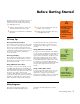
Before Getting Started This guide can help you get started using your new HP Media Center PC. You may want to browse some of the other documentation that came with your HP Media Center PC. 1 2 Read the “Safety Information” section in the documentation that came with your PC. Identify the items included with your HP Media Center PC. w 3 4 Follow the setup information that came with your PC to connect your PC. Read this guide for information about using your HP Media Center PC.
To find these programs, click Start, choose All Programs, PC Help & Tools, and then select a program or folder. Updates from HP these updates. If you have turned off the Updates from HP feature, you will not receive these updates. To turn it back on, click Start, choose All Programs, PC Help & Tools, Updates from HP, and Re-enable Updates from HP. HP may send updated information or patches to your desktop (not available in all countries/regions).
Selecting an Internet Service Provider As part of the startup screens, you can select an Internet service provider (ISP). Before you can connect to the Internet, you must sign up with an ISP. You must have an Internet connection to use some of the Media Center features. Easy Internet Sign-up helps you sign up for a new Internet account, set up an existing account, or configure Internet access using a LAN (local area network), cable modem, or DSL (digital subscriber line).
Protecting the PC HP provides a virus-scanning software program to help protect your PC (select models only). The virus-scanning program manufacturer provides free virus scan updates through your Internet connection for an initial period after your PC purchase. You can purchase a subscription service for updates after the initial free period expires. New types of viruses are invented all the time. Protect your PC by getting regular updates of your virus-scanning software from the program manufacturer.
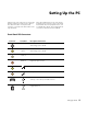
Setting Up the PC Follow the steps in the setup poster to set up the PC and then read the topics in this section to find out more about the location of components and connectors on your PC, and to find out about some setup alternatives. Most of the hardware devices such as the monitor, keyboard, printer, and mouse can be connected at the back of the PC. Some peripheral devices, such as a digital video camera, can be plugged into the connectors on the back or the front of the PC.
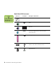
Back-Panel PC Connectors n Connector Icon/label Description and function Power connector Location, availability, and number of connectors may vary. Mouse Keyboard SERIAL Serial port for digital cameras or other serial devices (Select models only) Printer (parallel) Universal Serial Bus (USB 2.
Connector ETHERNET Icon/label Description and function ETHERNET Ethernet LAN connector The network interface adapter (also called a network interface card, or NIC) connects to an Ethernet (10BaseT) or Fast Ethernet (100BaseT) network hub. Connect this adapter in your PC to your local area network (LAN) hub or any broadband connection. Plug a network cable into the Ethernet (RJ-45) port on the back of the PC. Plug the other end of the network cable into a 10BaseT or 100BaseT port on the network hub.
Connector Icon/label Composite Video Description and function Composite Video In from set-top box connector L audio Left audio input from set-top box connector R audio Right audio input from set-top box connector TV/Cable Ant FM Ant TV In (TV antenna or cable input from wall outlet with no set-top box) FM In (radio antenna input) Plug the FM radio antenna cable into the FM In port on the back of the PC. The FM connector is found on the TV tuner card.
Connecting a Digital Video Camera to the PC When connecting an analog camera to the PC, use the Video and Audio In connectors on the front of the PC. The following instructions only apply to digital cameras. See the documentation that came with your digital video camera. 1 2 3 Turn on the PC, and wait for Windows XP to start. . n Connect the video camera transfer cable into the camera and then into an open port on the front or back of the PC.
Connecting to Other Devices n Some peripheral devices are not included with the PC. 10 Other peripheral devices can be connected to the front or back of your HP Media Center PC by using USB or FireWire ports. You can connect peripheral devices such as a printer, scanner, video camera, digital camera, memory card reader, and PDA (personal digital assistant) or handheld computer to the PC. See the documentation that came with your device.
Connecting the Television Signal Using TV Cables You may need purchase some cables separately, depending on your TV and the TV signal setup you choose. For example, when your TV has an S-video connector, you may want to use an S-video cable to connect the TV out on the PC to your TV. An S-video cable provides separate color and black-and-white image signals and delivers a sharper image than a composite video cable does. .
Optional Audio and Video Cables Not Included You might need the following extra cables. Your HP Media Center PC does not come with the following cables. Cable Name Description Splitter Used with coaxial cable for VHF and UHF antenna combinations. DVI-I or DVI-D Digital Video Out. Connect to DVI-I or DVI-D input of the HDTV capable TV or monitor. RCA stereo RCA red, white ends. Used for Audio In/Out connectors. Component video RCA red, blue, green ends.
Using the Analog Video Cable (Select models only) D n Analog Video E Refer to the Start Here guide for more information about the various display connection options. If you are using the analog video cable to connect your PC display to your PC, you need to connect the cable and then set the Output switch on the cable to match the correct video output. If you are using component cables, you must also set the resolution of your TV or other video display on the analog video cable.
6 Set the switch to match your display resolution. Move 2 (1080i), or 3 (720p), or 4 (480p/576p) to the On position (C). Or leave all of the switches in the Off position for 480i/576i only resolution. C 7 8 9 Connect the S-video, composite, or component video cables to the analog video cable and then to the back of the PC. Connect the power and turn on the PC. If the resolution is not correct, turn off the PC and disconnect the power.
Connecting the TV Signal Source Connect the signal source for the TV by using the TV In coaxial connector or the composite/S-video In connector. Plug the other end of the cable into your set-top box or other device that is providing the signal source for the TV. Plug the connector of a coaxial cable from your TV or from your TV cable into the TV/Cable Ant connector on the back of the PC, and then turn the connector to tighten it.
Connecting the Remote Sensor The remote sensor is a small device that connects to the PC and allows the remote control to work with the Media Center program. 1 2 3 If you have a cable TV set-top box, a satellite set-top box, or other set-top box that controls your TV signal, connect the remote control sensor cable (emitter) (A) into connector (1) on the back of the remote sensor.
Connecting the TV Signal Source When You Have an Existing Setup This section describes how to connect the PC to an existing setup for your TV signal source. Wall to VCR to TV using coaxial cable Remove the coaxial cable at the input to the VCR, and connect it to the input of a coaxial cable signal splitter (not included; available at electronics stores). Connect two coaxial cables to the splitter outputs.
Wall to cable TV set-top box or satellite box to VCR to TV using coaxial cable Remove the coaxial cable at the input to the VCR, and connect it to the input of a coaxial cable signal splitter (not included; available at electronics stores). Connect two coaxial cables to the splitter outputs. 18 HP Media Center PC Getting Started Guide Connect one of these cables to the input of the VCR and the other one to the TV connector on the back of the PC.
Existing setup Add the PC with a splitter A A B B C C D D E E M C N J C K C L F F G G C C H H A Wall B Cable C Coaxial cable D Set-top box/Satellite In E Set-top box/Satellite Out F VCR In G VCR Out H TV In J Splitter In K Splitter Out L TV In on back of PC M Remote control sensor cable N Remote control sensor Connecting the Television Signal 19
Wall to cable TV set-top box or satellite box to VCR and TV using S-video cable or composite video cable between the box and the VCR or TV 1 2 Do not detach any cables from your existing setup. Connect an additional cable: ■ Using S-video cable (not included): Connect an additional S-video cable to a second output on the set-top box or satellite box. Plug the other end of the cable into the S-video In connector on the back of the PC.
. Existing setup A Add the PC A B B C C D D L M J E K F F G G E H H A Wall B Cable C Set-top box/Satellite In D Set-top box/Satellite Out E S-video or composite cable F VCR In G VCR Out H TV In J Add an S-video or composite cable with adapter K S-video In on back of PC L Remote control sensor cable M Remote control sensor Connecting the Television Signal 21
Using the TV as a Monitor If your Media Center PC has TV-out capability (select models only), you can connect it to a TV to view the PC image on a TV screen. With the TV-out feature, you can view the PC image, watch DVD movies, or play games on your TV. This is an optional feature. Cables for connecting to a TV To connect a TV to the PC, you will need a video cable and an audio cable. The type of video cable you need depends on your TV: ■ ■ If your TV has an S-video input jack, you need an S-video cable.
4 If your TV has a composite video jack and your PC has a composite video jack, connect a composite video cable (A) to the Video In jack on the TV and to the composite video out jack (C) on the back of the PC (select models only). A 5 6 . B C Turn on the TV and select the TV In video source; refer to the documentation for your TV set. Enable the image for the TV.
Using the Media Center Setup Wizard for Optional Setup of Your TV Display n If you choose the option Preview Automatic Adjustment, the screen may appear black or seem to halt for approximately 20 seconds. Wait until the wizard screen reappears, choose Do not adjust any settings, click Next, and then continue with the next step in this procedure.
Changing the Display for a GeForce 6600 Graphics Card 1 2 3 Follow the “Using the Media Center Setup Wizard for Optional Setup of Your TV Display” on page 24. Click the GeForce 6600 tab. Click nView Display Settings. 4 5 6 Select the Device Settings button, and then you can select the various screen adjustment settings. Click Apply, and then click OK. Click OK again to close the window.
Viewing the PC image on the TV n The type of video card on your PC determines how the PC selects the TV-out option. Some options and menus in this procedure may be different for your PC. To view your PC image on the TV: 1 2 3 4 Make sure the video and audio cables are connected before you turn on the TV and the PC. 5 6 7 Turn on the TV. Make sure the Video input setting is selected, not the TV setting. Turn on the PC.
Displays tab 1 2 Click the Displays tab. This tab shows a monitor and a TV. The upper-left corner of each display icon is a button and a status indicator. A red corner indicates an inactive display; a green corner indicates an active display. To view the PC image on your PC monitor and your TV simultaneously, click the upper-left corner of the TV icon so that it is green. Click Apply. To view the PC image on just the TV, click the TV corner so it is green, and then click the monitor corner so it is red.
Ge Force FX tab (disabling) 1 2 3 Click the Ge Force FX xxxx tab. 4 In the area nView Modes select Single Display from the drop-down list. In the area Current display select Analog Display or Digital Display. 5 Click the Apply button. When the PC image appears on the TV screen, click Yes to keep the setting. You have 15 seconds to accept this new setting before it reverts to the previous setting. Click the OK button to save changes, and then click OK again to close the Display Properties window.
Configuring Speaker and Sound Options HP Media Center PCs support many different audio options, sound connections, and speaker configurations. You may set up your PC for two stereo speakers or for multichannel audio speaker systems. Connect your speaker system to the PC, and then configure the audio software for sound output. For more details about connecting stereo speakers to the PC, see the setup poster. This chapter describes the most typical options. Your system may have different components.
Connector Description Illustration Type Sound card connector Your PC may include a sound card. You can connect up to a 5.1 audio system (7.1 audio system for select models) or digital speakers to the sound card on the PC. See below. S Use the sound connectors that match your PC model when installing cables, as shown in the installation procedure steps. n 3 is three connectors The following table shows the sound connectors on the back panel of PC systems.
Sound connector 3 6 IN DIGITAL AUDIO OUT DIGITAL AUDIO OUT S Description E Line In (light blue) connects to an analog audio device such as a CD player for input into PC. (3: Also functions as rear Line Out when a multichannel audio configuration is activated.) F Digital Out (orange) connects to a digital audio device with digital input (such as a home audio receiver/amplifier) or digital speakers (select models only).
Speaker types Speakers may be included with the monitor (select models only) or are sold separately. Refer to the product documentation for your speakers. Your PC supports only an active (powered) speaker system. An active speaker system must have its own power cord. A home audio system does not require active speakers because the receiver provides amplification. A stereo speaker set is a left-right, two-channel speaker system.
Step 8 is optional for a two-speaker setup. 8 After the speakers are connected to the PC, configure the audio software for sound output for your PC model: ■ ■ 6 connectors: See “Configuring Audio Output with Sound Effect Manager” on page 47. ■ Sound card: See “Configuring Audio Output with a Sound Card” on page 49. 3 connectors: See “Configuring Audio Output with Multi-channel Sound Manager” on page 44. The following diagram shows a typical 2.1 audio installation: OUT Connecting 4.
4 5 6 7 8 Connect the cables to the audio system. 9 Connect the front and rear speakers to the subwoofer. Refer to the speaker documentation. After the speakers are connected to the PC, configure the audio software for sound output for your PC model: ■ 3 connectors: See “Configuring Audio Output with Multi-channel Sound Manager” on page 44. ■ 6 connectors: See “Configuring Audio Output with Sound Effect Manager” on page 47. ■ Sound card: See “Configuring Audio Output with a Sound Card” on page 49.
4 Connect the center/subwoofer speaker cable to the gold (or pink Mic) connector that matches the back of your PC. 3 6 S 7 Turn on the PC. 8 Plug in the speaker system power. 9 Turn on the speaker system. 10 After the speakers are connected to the PC, configure the audio software for sound output for your PC model: ■ 5 6 For 3-connector systems, the pink Mic connector functions as a center/subwoofer speaker Line Out when a multichannel audio configuration is activated.
Connecting 7.1 Audio Speakers If your PC has 6 connectors or an Audigy2 ZS sound card (select models only), you can install an 8/7.1 audio system. To connect two front speakers, two side speakers, two rear speakers, a center speaker, and a subwoofer for eight-channel (7.1 speaker) output: (Select models only) 1 n . 2 Turn off the PC. 5 Connect the front speaker cable to the lime-green Audio Line Out connector on the back of your PC.
The following diagram shows a typical 7.1 audio installation: Connecting 7.1 Speakers to a Sound Card If you have a sound card and you want to connect 7.1 speakers, you must purchase Creative Inspire T7700 speakers.
Connecting the PC to a Home Audio System You can connect your HP Media Center PC to your home stereo or home theater multichannel audio receiver/amplifiers using your existing speakers. For example, see “2.1 home stereo installation” on page 39, or “6/5.1 home audio installation” on page 40. Y adapter cables n Y adapter and extension cables are purchased separately. Most home receiver/amplifiers have RCA-type input connectors.
2.1 home stereo installation The following diagram shows a typical two-channel (2.1) speaker installation that uses passive stereo speakers and plugs into a home stereo standard left and right input. This is only a suggested configuration. Your system may be different. IN OUT A A: PC back-panel connectors (3, 6, or sound card) B: Y adapter cables B C: Receiver/amplifier D: Subwoofer C E: Front speakers (left and right) D E PC to 2.
6/5.1 home audio installation The following diagram shows a typical advanced home theater audio six-channel 6/5.1 speaker installation that requires multichannel inputs on a receiver/amplifier. A IN OUT n A: PC back-panel connectors (3, 6, or sound card) This is only a suggested configuration. Your system may be different. B B: Y adapter cables C: Receiver/amplifier D: Subwoofer C E: Center speaker F: Front speakers (left and right) G: Rear speakers (left and right) D E PC to 5.
6/5.1 home audio installation procedure To connect a six-channel (5.1 speaker) home audio system to the PC: 1 2 3 Connect the front stereo mini-jack end of a Y adapter cable into the lime-green Audio Line Out connector that matches the back of your PC. ■ 4 6 Connect the left and right ends of the Y adapter cable into the front left (L) and right (R) inputs on the back of the receiver/amplifier.
Connecting Digital Audio (Select models only) If you have a sound card and you are connecting your home stereo AV receiver via Digital Out, plug the 3.5 mm stereo plug into the digital out connector on the sound card. Connect the red RCA stereo plug on the 3.5 mm Y cable to the AV receiver’s digital input connector. If the red RCA stereo plug does not work, try the white stereo plug. One of the connectors is not used.
Configuring Audio Output You can configure your speaker’s audio output with the following software.
Configuring Audio Output with Multi-channel Sound Manager Follow these steps after you have installed and connected your speakers, if your PC model has 3 Connectors. To configure multichannel audio output for PCs with Multi-channel Sound Manager: 1 2 44 Click Start on the taskbar. Choose All Programs. 3 Click Multi-channel Sound Manager. The Multi-channel Audio Configuration window opens with one of five control screens. ■ Sound Effect — Select the environment settings.
4 5 6 Click the Speaker Configuration tab near the top of the window to open the control screens. (Your speakers may need to be plugged in to see this tab.) Select the option describing the number of speakers in your system, in a range from 2/2.1 speaker mode to 6/5.1 speaker mode. 7 8 9 Click OK. Test the speakers. Click the Speaker Test tab. Follow the instructions. Configure audio output for the Media Center. See “Configuring Audio for Media Center” on page 50.
Sound Effect Manager Sound Effect Manager displays one of the following control screens: ■ ■ 46 Sound Effect — Select the environment and the equalizer settings. You can select an environment, such as Under Water or Auditorium. To use the equalizer, click the Power button in the center of the circular equalizer control to turn on the equalizer. You can click a preset button, such as Pop or Live, or manually adjust the settings and save them for selection later.
Configuring Audio Output with Sound Effect Manager Follow these steps after you have installed and connected your speakers, if your PC model has 6 connectors. To configure multichannel audio output for PCs with Sound Effect Manager: 1 2 3 Click Start on the taskbar. Click Control Panel. Click Sounds, Speech and Audio Devices (or Sounds and Audio Devices). 4 5 Click Sound Effect Manager. The window opens. Click a button near the top of the window to see that control screen.
5 6 7 Click Sound Effect Manager. The window opens. Click Audio Wizard. A window opens that shows the connector panel on the front of the PC. 8 9 Connect the speaker system audio cable plugs into the connectors on the front of your PC. The panel display highlights a cable that is properly inserted in a connector. Close the window. Place a check in the Enable jack detection check box to enable the wizard.
Configuring Audio Output with a Sound Card Follow these steps after you have installed and connected your speakers. To configure multichannel audio output for PCs with the Creative Sound Blaster Audigy sound card: 1 2 3 4 5 Click Start on the taskbar. Choose All Programs. Choose Creative, SoundBlaster Audigy 2. Click Creative Speaker Settings. The speaker settings window opens. Select a speaker setting from the Speaker/ Headphone Selection drop-down menu. Enter a speaker configuration from 2/2.1 to 2/7.
Configuring Audio for Media Center Follow these steps after you have installed, connected, and configured your speakers. To configure multichannel audio output for the Media Center: 1 2 3 Click Start on the taskbar, scroll down, and select Media Center. Click Settings, click DVD. Scroll down and click Audio. Select Speaker Configuration. 4 5 6 Select your Speaker Configuratiuon by clicking on the (+) or (–). If you select Analog-2 Channel, then select the channel mode by clicking the (+) or (–).
Using Headphones You can also connect headphones to the Line Out connector (lime-green) on the back of your PC. OUT Your PC comes with a headphones connector (lime-green) on the front of the PC. The headphones connector is labeled with a headphones icon. Using a 2.1 speaker system For select models with the 2.1 speaker system, look for the headphones connector on the right side of the main speaker. When headphones are plugged in, the sound to the speakers and the subwoofer is muted.
Resolving Sound Issues If you don’t have sound from your speakers, check the following: 52 ■ Check volume and mute settings. See “Using Headphones” on page 51. ■ Reconfigure the sound software for surround sound. ■ Verify sound cable connections. ■ ■ Reinstall the sound card drivers by using HP Application Recovery. See “Application Recovery” in the Warranty and Support Guide. Use active, powered speakers, or speakers with an amplifier.
Using the PC Hardware Using the Keyboard Your PC may include a standard keyboard or a wireless keyboard. A standard keyboard connects to the keyboard connector in the back of the PC. A wireless keyboard (select models only) uses a receiver/transmitter, instead of a connector cable, to communicate with your PC. A light on the receiver indicates receiver activity. The keyboard has an arrangement of standard keys, indicator lights, and special buttons.
Media control or playback buttons n Icon The Volume knob can continue to be turned, even after maximum sound has been reached. + Label Description Eject 1 and Eject 2 Opens or closes upper and lower optical drive trays. Rec Starts recording to selected media. Stop Stops media. Play/Pause Plays or pauses media. Prev Rewinds media. Next Fast-forwards media. Volume Volume knob controls speaker volume. Or n The number, location, and labeling of buttons may vary by keyboard model.
Using the Remote Control Use the remote control to open the Media Center program, and use it to view TV, record TV programs, play previously recorded TV programs, and play music, movies, or video. To use the remote control, simply point it at the remote sensor and press the Start button. n Use the remote control at a maximum distance of 8 meters (26 feet) from the remote sensor and at a maximum of 22.5 degrees (45 degrees total) from the center of the remote sensor.
Memory Card Reader w Digital cameras and other digital imaging devices use memory cards, or media to store digital picture files. The optional memory card reader can read and can write to a variety of types of memory cards and the IBM Microdrive disk drive. Do not try to remove media when the inuse light is blinking. Doing so may cause loss of data. The card reader is accessible directly on the front of the PC.
Formatting a memory card If you have not used the memory card, you may need to format it first. 1 Format your memory card in your digital camera. Follow the instructions that came with your digital camera. HP recommends formatting your memory card in your digital camera. 2 3 4 Or 1 Insert the media into the correct card slot on the reader until it stops and locks into place. The light on the reader lights, and the computer automatically detects the media. 5 6 Click Start, and then click My Computer.
Troubleshooting the memory card reader n CompactFlash and Microdrive are keyed and cannot be inserted incorrectly. Insert the receptacle edge (holes) of this media into the slot. If you are having problems reading to or writing to a memory card, try the following: ■ Make sure the read/write switch on the memory card, if available, is set to Write Enabled. ■ Make sure the amount of data you want to store is not larger than the capacity of the memory card.
Using Your Storage or Docking Bay Your PC may have a docking bay (select models only) on the top of the PC. You can use the docking bay to: ■ Store CDs, DVDs, or memory cards. ■ Dock a peripheral device in the back, such as a digital camera docking station. ■ Install a special cover (optional) and an HP digital camera and HP digital camera docking station. (Both the HP digital camera and the camera docking station are sold separately.
4 Thread the cables (C) that came with your camera docking station through the cable tunnel, starting from the back of the PC and threading them to the front of the PC. Pull cables to the center. DC IN 5 Connect the cables: ■ Plug the USB cable into the back of the PC. (The location of USB ports varies by PC model.) ■ Plug the red and yellow connectors (not shown) into a TV if you want to view the camera images on a TV (optional). ■ Plug the power cord into a power outlet. ■ DC IN .
6 7 8 Place the correct camera docking station lid (D) on top of the PC. Gently guide the edge of the lid into the top of the PC. E Place the HP digital camera (E) into the camera docking station. Follow the instructions that came with your camera docking station. D Installing an iPod Dock n To install the iPod dock: 1 2 Gently press down the CD storage lid, and slide it open. Place the iPod Dock (H) on the top of the PC.
3 4 Thread the USB cable that came with your iPod Dock through the cable tunnel, starting from the back of the PC and threading them to the front of the PC. Pull cable to the center and connect them to the back of the iPod Dock (K). K Connect the USB cable into the back of the PC. Refer to the instructions that came with the iPod.
5 6 7 Place the iPod Dock lid (L) on top of the PC. Gently guide the edge of the lid into the top of the PC. When you want to use it, place the iPod (M) into the docking station. M Follow the instructions that came with your iPod.
Connecting the Wireless LAN n The wireless LAN antenna connector is located either below the fan or in one of the I/O slots on the back of the PC. (Select models only) You can connect the HP Media Center PC to an 802.11b/g wireless network. An external antenna is supplied with your system. You must connect this antenna to connect to the wireless network. You need an existing wireless LAN with an Internet connection (consult your ISP for further information).
Troubleshooting For help on general and miscellaneous problems you may be experiencing with the PC, refer to: ■ The other troubleshooting documentation that came with your PC. ■ The following pages in this section. ■ The topics in Help and Support. Press the Help button on your keyboard, or click Start on the taskbar and select Help and Support. n If you need Audio I don’t have sound from my speakers. ■ Check Volume and Mute settings. See“Configuring Speaker and Sound Options” on page 29.
My software stopped working. Refer to the sections about Application and System Recovery in the other documentation that came with your PC to reinstall a software program. If your program came on a CD, follow the instructions that came with the software to reinstall it. Codec errors are occurring when I play certain files. Codec is an abbreviation for compressordecompressor. A codec is software or hardware used to compress and decompress audio/video files.
System and Hardware w My remote control doesn’t work. See “Troubleshooting the remote control” on page 55. My remote sensor is not receiving a signal from the remote control. If a faint red light doesn’t appear when you point the remote control at the remote sensor and press the OK button, try the following: 1 2 3 Click Start, right-click My Computer, and then select Properties. Click the Hardware tab, and then click Device Manager. Click the plus (+) sign next to Universal Serial Bus Controllers.
The memory card reader won’t read my memory card. ■ ■ Do not insert or remove memory cards when the in-use light is flashing. To do so may cause data loss, or it may permanently damage the card reader. ■ Format a memory card before you use it. See “Formatting a memory card” on page 57. ■ Some cards have a read/write or security switch on the card. Make sure the read/write switch is set to Write Enabled before attempting to write data to it.
Index A analog video cable using 13 audio connector 7 B backing up PC data 3 batteries installing in remote control 55 type for remote control 55 buttons media control or playback 54 On 2 C cables connecting PC to TV 22 included 11 not included 12 TV 11 camera docking station, installing 59 coaxial cable connecting the TV signal source 18 codec errors 66 CompactFlash reader 56 Composite Video In connector 8 computer connecting the remote sensor 16 connecting the TV signal source 15 getting started 1 keybo
I P installing camera dock 59 camera docking station 59 Internet service provider 3 PC K keyboard connector 6 keys 53 using 53 keyboard buttons access 53 configuring 54 media playback 54 not working 65 special 53 L LAN antenna 64 M Media Center opening with remote control 55 memory card reader in-use light 57 troubleshooting 58 using 56, 57 memory card, formatting 57 Memory Stick (MS) reader 56 Memory Stick Pro (MS-Pro) reader 56 Microdrive reader 56 microphone connector 5 modem connector 8 monitor co
resolving sound issues 52 setting up digital speaker output 49 standby mode button 53 stereo connecting to the PC 38 S-video In connector 7 T transfer wizard 3 transferring old PC information to a new PC 3 troubleshooting keyboard buttons not working 65 memory card reader 68 remote control 67 remote sensor 67 sound 65 turning on computer 2 TV connecting 22 connecting the TV signal source 15, 17, 20 disabling the TV option 27 disconnecting 28 setting up 26 using as a monitor 22 TV tuner connecting TV to PC
Part Number: 5991-2313 72 HP Media Center PC Getting Started Guide