
Mellanox MLNX-OS User Manual for SX1018HP Ethernet Managed Blade Switch


Rev 2.10
Mellanox Technologies
528
Mellanox Technologies Confidential
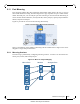
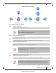
Figure 14: Header Format Options
SourceFrame MirrorFrame
SourceFrame MirrorFrame
SourceFrame MirrorFrame
SourceFrame MirrorFrame
Data
Type/
Len
SADA
Data
Type/
Len
SADA
Data
Type/
Len
SADA
Data
Type/
Len
SADA Data
Type/
Len
SADA
Data
Type/
Len
SADADA SA
0x8949
Data
Type/
Len
SADADA SA
0x89490x8100
VLAN
Data
Type/
Len
0x8100
DA VLANSA
local
add‐vlan
add‐ethernet‐header
add‐ethernet‐header
(+vlan)
5.11.1.4 Congestion Control
The destination ports might receive pause frames that lead to congestion in the switch port. In
addition, too much traf
fic directed to the analyzer port (for example 40GbE mirror port is
directed into 10G analyzer port) might also lead to congestion.
In case of congestion:
• When best effort mode is enabled on the a
nalyzer port, SwitchX drops excessive traffic
headed to the analyzer port using tail drop mechanism, however, the regular data (mir-
rored data heading to its original port) does not su
ffer from a delay or drops due to the
analyzer port congestion.
• When the best effort mode on the analyzer port is d
isabled, the SwitchX does not drop
the excessive traffic. This might lead to buffer exhaustion and data path packet loss.
The default behavior in congestion situations is to drop any exc
essive frames that may clog the
system.
5.11.1.5 Truncation
When enabled, the system can truncate the mirrored packets into smaller 64-byte packets
(defau
lt) which is enough to capture the packets’ L2 and L3 headers.
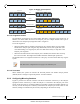
5.11.2 Configuring Mirroring Sessions
Figure 15 presents two network scenarios with direct and remote connectivity to the analyzer
equipment. Direct connectivity is when the analyz
er is connected to the analyzer port of the
switch. In this case there is no need for adding an L2 header to the mirrored traffic. Remote con-
nectivity is when the analyzer is indirectly connected to the
analyzer port of the switch. In this
situation, adding an L2 header may be necessary depending on the network’s setup.
ETS, PFC and FC configurations do not apply to the destination port.