HP Modular Cooling System 200/100 Site Preparation Guide Abstract This document provides site preparation guidance for the MCS-200/100.
© Copyright 2014 Hewlett-Packard Development Company, L.P. The information contained herein is subject to change without notice. The only warranties for HP products and services are set forth in the express warranty statements accompanying such products and services. Nothing herein should be construed as constituting an additional warranty. HP shall not be liable for technical or editorial errors or omissions contained herein. Restricted rights legend Use, duplication or disclosure by the U.S.
Contents Overview ..................................................................................................................................... 5 Overview .................................................................................................................................................... 5 Product overview .......................................................................................................................................... 8 Key components .........................
Appendix B: Conversion factors and formulas ................................................................................ 85 Conversion factors and formulas .................................................................................................................. 85 Conversion factors for refrigeration .................................................................................................... 85 Metric equivalents ..........................................................................
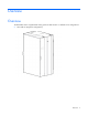
Overview Overview The MCS-200/100 is a supplemental cooling system for data centers.
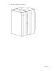
• MCS-100 unit (dual-rack configuration) Overview 6
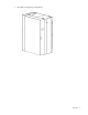
• MCS-200 unit (single-rack configuration) Overview 7
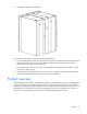
• MCS-200 unit (dual-rack configuration) For successful site preparation, consider the following information: • To provide dedicated cooling for servers and other IT equipment, the MCS-200/100 integrates with the facility chilled water plant or a dedicated chilled water loop. HP recommends that you install a dedicated cooling loop to the MCS-200/100. • The system provides cooling, recirculation, and condensation management, and it requires a small amount of AC electric power.
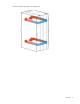
Air flow for MCS-100 (single-rack configuration) Overview 9
Air flow for MCS-100 (dual-rack configuration) Overview 10
Air flow for MCS-200 (single-rack configuration) Overview 11
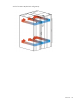
Air flow for MCS-200 (dual-rack configuration) The special horizontal airflow of the MCS-200/100 fully supports the industry standard front-to-back cooling principle, such as cold air drawing into the front of the server and warm air being expelled out the rear of the unit. All devices receive adequate and evenly distributed cool air regardless of the mounting position within the enclosure. The MCS-200/100 distributes precisely cooled and targeted air flow evenly across the front of the IT equipment.
• Fan controller—Operates the fans, according to the cabinet air temperature • Air bleeder valve—Enables air to manually bleed out of the system when coolant is initially filled • Water controller—Senses condensation, leaks, water temperatures, flow rate, and the status of the water valve, and sends this data to the management module • AC input/network connection—Provides primary and secondary AC input connections, if available, and a network management interface • AC transfer switch—Provides dual-
Item Description 1 Control valve 2 Flow meter 3 Humidity sensor 4 Heat exchanger unit 5 Fan units (1 fan by default, 4 fans maximum) 6 Management module HP provides several components to complement or complete your MCS-100. For more information, see the HP Modular Cooling System 200/100 Options Installation Guide. The following illustrations show the MCS-100 optional components.
Item Reference 7 Heat exchanger unit 8 TFT touchscreen display (optional) 9 Fan units (1 fan by default, 4 fans maximum) 10 Management module Unit top view For easier viewing, the canopies are not shown in this illustration.
The following illustrations show the MCS-200 optional components.
For easier viewing, the canopies are not shown in this illustration. Item Reference 1 Water module 2 Fan module 3 Condensation pump transformer 277v (optional) 4 AC transfer switch 5 Emergency door opening Physical specifications The following table lists the approximate physical specifications of a single MCS-100 or MCS-200 as received from the factory.
Parameter Unpackaged CTO system Packaged system (as Unpackaged system shipped on pallet) (off pallet, unwrapped) Height 2159 mm (85 inches) 2007 mm (79 inches) 2007 mm (79 inches) Width 914.4 mm (36 inches) 600 mm (23.6 inches) 600 mm (23.6 inches) Depth 1727 mm (68 inches) 1200 mm (47.2 inches) 1200 mm (47.
Parameter Value Comments Power cord 230 V, 16 A 208 V, 18 A IEC 309-to-Procon 700105 NEMA L6-20-to-Procon 700105 The following table lists the electrical specifications for the MCS-200 unit.
Facility planning for implementation Facility planning overview The MCS-200/100 offers an incremental data center cooling solution, capable of cooling 30 kW of heat with the MCS-100 unit or 50 kW of heat with the MCS-200 unit. In planning water supply and design, take into consideration short and long-term needs for cooling. Immediate supply needs must meet the specifications and target cooling requirements, based on the parameters defined in this site preparation guide.
Delivery space requirements Be sure your facility has adequate space to receive and remove the MCS-200/100 from the shipping pallet. Consider the following when unloading the racks: • Forklifts must enter and transport the shipping pallet from the side. • Delivery plans must include the possible removal of walls or doors. MCS-200/100 dimension requirements Dimension requirements MCS-200/100 MCS expansion rack Total length allowed to safely remove the MCS-200/100 approximately 6.
CAUTION: HP recommends that a ramp angle of no greater than 5° be used to move the MCS-200/100 up or down elevations. Typical data center ramps have a 5º angle (1 to 12 pitches).
MCS-200/100 expansion rack Item Reference 1 MCS-200/100 expansion rack shock pallet 2 4-piece ramp 3 MCS-200 expansion rack (MCS-100 expansion rack not shown) Operational space requirements To provide space for internal airflow and housing of the cooling unit components, the MCS-200/100 is wider and deeper than conventional HP racks. HP recommends the minimum access space for the MCS-200/100 be 1219 mm (4 ft) in the front and 914 mm (3 ft) in the rear, as shown in the following figures.
MCS-100 unit (single-rack configuration) MCS-100 unit (dual-rack configuration) Facility planning for implementation 24
MCS-200 unit (single-rack configuration) MCS-200 unit (dual-rack configuration) System positioning The MCS-200/100 can be installed next to an existing or new row of HP Intelligent Series racks. Based on facility design requirements, the cabinets can be arranged in a flush front or flush rear configuration.
Flush front configuration examples When arranging the MCS-100 or MCS-200/100 next to an HP Intelligent Series rack, and depending on the configuration, be aware of the potential for slight rear door swing interference. Equipment might require the removal of a door during installation to allow for unimpeded access. Cable openings The MCS-100 and MCS-200 units have several useable cable openings at front top, rear bottom and rear top of the IT rack.
• Bottom view The following figure shows the size and position of the cable openings at the top and bottom in the MCS-100 (dual-rack configuration). • Top view • Bottom view The following figure shows the size and position of the cable openings at the top and bottom in the MCS-200 (single-rack configuration).
• Top view • Bottom view The following figure shows the size and position of the cable openings at the top and bottom in the MCS-200 (dual-rack configuration).
• Top view • Bottom view Cabinet leveling feet Facility planning for implementation 29
WARNING: Static loading limits cannot be achieved if the rack is not on its leveling feet or is rolled or pushed from its position. Your floor weight capacity might not support the full static load capacity. Check with your floor provider before loading. HP is not responsible for floor damages due to floor overloading. CAUTION: To reduce the risk of damage to the casters, make sure that the full weight of the rack rests on the leveling feet and feet pads, and not on the casters.
o • MCS-100 dual-rack configuration IT rack side view Facility planning for implementation 31
o MCS-100 single-rack configuration Facility planning for implementation 32
o MCS-100 dual-rack configuration MCS-200 cabinet leveling feet locations: • Bottom view Facility planning for implementation 33
o MCS-200 single-rack configuration Facility planning for implementation 34
o • MCS-200 dual-rack configuration IT rack side view Facility planning for implementation 35
o MCS-200 single-rack configuration Facility planning for implementation 36
o MCS-200 dual-rack configuration The leveling feet pads help to ensure weight distribution and help transfer the load to the support structure below the floor. You must ensure proper orientation of the feet pads so that subsequent racks can be properly accommodated. Floor loading considerations The computer room floor must be able to support the total weight of the installed server trays as well as the weight of the MCS-200/100 as they are moved into position.
The MCS-200/100 has not been certified for seismic environments. The following table can be used to calculate the weight load of each MCS-200/100 unit, including installed equipment for proper floor planning. MCS-100 weight calculation Component Unit weight Quantity (multiple by) Total weight MCS-100 (with no server trays) 670 kg (1479 lb) 1 670 kg (1479 lb) Component #1: HP ProLiant SE2x8530a Gen8 Server Tray* 11.21 kg (24.
The weight distribution on the leveling feet locations in MCS-100 and MCS-200 are very similar.
Item Weight A 385 kg (849 lb) B 455 kg (1003 lb) C 458 kg (1010 lb) D 385 kg (849 lb) E 375 kg (827 lb) F 457 kg (1007 lb) G 457 kg (1007 lb) H 375 kg (827 lb) CAUTION: To reduce the risk of damage to the casters, make sure that the full weight of the rack rests on the leveling feet and feet pads, and not on the casters. The casters are designed only as an aid in moving the rack into position.
The MCS-200 provides two Walther Procon A5 series AC input connections and ships with one set of two power cords for connecting to redundant AC power busses, when available. Only one power cord is necessary for operation. The second cord can be connected to a redundant AC power bus to improve system availability by protecting against power source failures or accidentally tripped circuit breakers. These redundant connections and cords are optional for the MCS-100.
MCS-200 Raised floor grounding Item Description 1 Ground wire to power panel 2 Floor panel 3 Hex bolt 4 Grounding grid element 5 Grounding braid to computer equipment 6 Band and pedestal 7 Grounding clamp Facility planning for implementation 42
Voltage fluctuations and outages The MCS-200/100 is designed to provide immunity to power outages of less than one cycle. However, testing cannot conclusively rule out loss of service.
MCS-200/100 power L6-20 connector MCS-200/100 IEC 309 power connector At least one power cord must be used for MCS-200/100 operation. To improve system availability, the second cord can connect to a redundant AC power bus (optional for the MCS-100). When the redundant power is connected, the transfer switch assembly of the MCS-200/100 provides switch-over to the active power bus, in the event of power source failures or accidentally tripped circuit breakers. The power cords of the MCS-200/100 are 4 m (13.
When using only a single, primary source for power, the AC power cord is connected to the left-most receptacle. When redundant AC power is available, the redundant AC power cord is connected to the right receptacle. Coolant source planning CAUTION: The minerals and chemicals typically found in tap water can react with metallic elements used in the HP Modular Cooling System 200/100 closed-loop distribution system.
• The water source should be shared water or dedicated facility water loop. • Maximum and minimum temperatures of building chilled water plant, and target chilled water temperature of dedicated loop, should be based on the total cooling capacity required and planned. • The viscosity of the chilled liquid, combined with the length and elevation changes in piping determined by selected route, can affect pipe size selection.
• Flow rate and pressure capacity of chilled water plant input to the design of the facility feed line and dedicated water loop pipe diameters • Material compatibility within piping system to minimize the potential for electrochemical corrosion, and must be corrosion-resistant • Minimization of elbows and other restrictions that increase flow resistance • Insulation of piping to minimize risk of condensation and reduce incidental heating of supplied chilled water • Availability of a floor drain or
Item Description (quantity) 4 M6 screw (4) 5 5mm Hex L-key (1) 6 Warning label (2) 7 M5.5 x 10 self-tapping screw (8) 8 Hose mounting brackets with hose clamps (2) 9 Top cover plate (1) 10 Rear cover plate (1) *Not drawn to scale. The actual length of the main hose is approximately 3.5 m (11.5 ft). CAUTION: You must properly connect the cabinet and facility cool water inlet and warm water outlet hoses. The MCS-200/100 does include a check valve to prevent the reverse flow of coolant.
• Above the floor (for MCS-200 only) Facility planning for implementation 49
• Above the unit An HP Water Hook Up Kit must be installed prior to activating an MCS-200/100. The kit contains approximately 350 cm (138 inches) of flexible hose with terminated fittings on each end. The length that is available outside the MCS-200/100 depends on the preferred type of connection.
of 8 mm (0.31 inch). The preferred method of routing for all hoses is downward at an angle of at least 3º (pitch of 0.6 inch per 12 inches), without loops, and away from the MCS-200/100 cabinet. For MCS-200 only, pumped condensation and gravity-fed overflow hoses must be routed to a floor drain or reclaim system. Flexible attachment hoses are intended to allow for deflection in any direction for equipment mounted on dynamic platforms, or for slight relocation of cabinets.
The following figure shows the recommended facility piping approaches to the MCS-200/100. Item Description 1 Preferred piping location: locate chilled water piping taps behind the MCS-200/100—either under or above the floor. Chilled water taps must approach laterally. 2 Do not locate piping connections or components under the MCS-200/100. 3 Alternate piping location: locating chilled water piping taps in front of the MCS-200/100. Under the floor is possible.
• Bottom view • Top view MCS-200 hose openings Facility planning for implementation 53
• Bottom view • Top view Facility planning for implementation 54
• Rear view Raised floor cutouts for the MCS unit A complete MCS-200/100 installation typically requires the following floor cutouts in a raised-floor facility (standard rack configuration): • One floor cutout for the chilled water hoses and drain hoses of the cooling unit • One floor cutout for the power cords and data cables of the computer equipment rack, including power supply to the MCS-200/100. For more information on the top openings, see "Cable openings (on page 26).
Recommended floor cutouts (single rack configuration)—Option 1 (MCS-100 cooling unit side flush to tile) Facility planning for implementation 56
Recommended floor cutouts (single rack configuration)—Option 2 (MCS-100 rack side flush to tile) Facility planning for implementation 57
Recommended floor cutouts (dual rack configuration)—Option 3 (MCS-100 cooling unit side to tile) Facility planning for implementation 58
Recommended floor cutouts (dual rack configuration)—Option 4 (MCS-100 right side to tile) MCS-200 floor tile cutouts Facility planning for implementation 59
Recommended floor cutouts (single rack configuration)—Option 1 (MCS-200 cooling unit side and front flush to tile) Facility planning for implementation 60
Recommended floor cutouts (single rack configuration)—Option 2 (MCS-200 rack side and front flush to tile) Facility planning for implementation 61
Recommended floor cutouts (single rack configuration)—Option 3 (MCS-200 cooling unit side and rear flush to tile) Facility planning for implementation 62
Recommended floor cutouts (single rack configuration)—Option 4 (MCS-200 cooling unit side and rear flush to tile) Facility planning for implementation 63
Recommended floor cutouts (dual rack configuration)—Option 5 (MCS-200 cooling unit side and front flush to tile) Facility planning for implementation 64
Recommended floor cutouts (dual rack configuration)—Option 6 (MCS-200 rack side and front flush to tile) Facility planning for implementation 65
Recommended floor cutouts (dual rack configuration)—Option 7 (MCS-200 cooling unit side and rear flush to tile) Facility planning for implementation 66
Recommended floor cutouts (dual rack configuration)—Option 8 (MCS-200 cooling unit side and rear flush to tile) A wider opening in the back of the IT rack is optional with MCS-200. The floor tile sizes used in the above options are 600 mm x 600 mm (23.6 inches x 23.6 inches). Floor tile sizes vary. The allowable tolerances are +/- 3.2 mm (+/- 0.125 inch). When installing multiple MCS-200/100 units in a row, you must consider the tolerances as you plan the cutouts.
Recommended plumbing configuration for the MCS-200/100 Typical plumbing components for an MCS-200/100 configuration Item Description Specifications 1 Chilled water return line Pipe: 31.75-mm (1.25-inch), ASTM B 88, Type L, hard-drawn copper Fittings: ASTM B16.22 Wrought copper Solder: ASTM B 32, 95-5 Tin Antimony Thread sealant: seal and assemble according to local materials and practices 2 Flow/measurement balancing valve Valve type: 31.75-mm (1.
Item Description Specifications 6 Strainer isolation valves Valve type: 31.75-mm (1.25-inch), two-piece, full-port, brass ball valve, with chrome plated brass ball, PTFE seats, steel handle, with solder end connections. Pressure rating: 600 psi WOG, 150 psi WSP Orientation: Stem vertical up for lateral level operation. Offset valves on CHWS and CHWR piping to prevent interference from lever actuators when closed. Watts FBVS-3C or equivalent typical 4 7 Strainer Type: 31.75-mm (1.
Item Description Specifications 21 Test plug Type: Corrosion-resistant brass body with core inserts, gasketed and threaded cap, with extended stem for units to suit piping insulation thickness Watts TP or equivalent *The 1μm filter might require a minimum of 762 mm (30 inches) clearance under the floor for installation. If a filter cannot be installed under the roof because of space constraints, it may be installed further upstream in the pipe system.
Coolant requirements General thermal requirements The following table lists the coolant requirements that the facility must meet in order to support an MCS-200/100 installation. In addition to the requirements listed, the coolant must meet the requirements prescribed in the "Acceptable water quality specifications (on page 78)" section.
Cooling loop sizing Sizing the cooling loops can be straight forward based on the planned cooling requirements of each populated/planned MCS-200/100 server enclosure. The amount of heat, in watts, that needs to be removed from each component in the server rack must be added together to obtain the total heat to be removed by the MCS-200/100 cabinet. You can copy the following table for documenting individual cabinet calculations.
MCS-200/100 Number of fans HP Modular Cooling System 200/100 4 fans 30kW, 2,800 CFM 15kW, 1,400 CFM 30kW, 3,000 CFM 15kW, 1,600 CFM N+1 Redundancy N+1 Redundancy N/A N/A 40kW, 3, 750 CFM 20kW, 2,000 CFM or 30kW N+1 or 15kW N+1 5 fans 6 fans N/A HP Modular Cooling System 200/100 with Expansion Rack N/A MCS-200/100 with Expansion Rack 50kW, 4,500 CFM 30kW, 2,400 CFM or 40kW N+1, or 20kW N+1, or 30kW N+2 15kW N+2 Cooling performance is rated at 43 ˚F EWT.
When the minimum heat load is not provided to the MCS-200/100, unstable control of the temperatures and flow rates of the MCS-200/100 can occur. For more information, contact your HP representative. The following charts offer a guideline for determining the approximate amount of heat that can be removed from MCS-200/100 based on 20°C (68°F) and 25°C (77°F) server intake air temperatures (in degrees, Celsius), flow rates as liters per minute (lpm), or in US gallons per minute (gpm), delivered to the unit.
MCS-200 coolant flow requirements with 20°C (68°F) server intake air MCS-100 coolant flow requirements with 25°C (77°F) server intake air Facility planning for implementation 75
MCS-200 coolant flow requirements with 25°C (77°F) server intake air MCS-100 coolant flow requirements with 30°C (86°F) server intake air The following pressure-drop chart is provided as a reference to indicate water flow versus water pressure, for a fully-opened MCS-200/100 water control valve.
Flow rate versus delta pressure (water control valve fully open)—MCS-100 Flow rate versus delta pressure (water control valve fully open)—MCS-200 A minimum water pressure difference of 1.0 to 1.5 bar (15 to 20 psi) between facility supply and return is required. The previous figures give the pressure difference with a fully opened control valve.
available, the provided system pressure difference must be slightly higher than the maximum pressure loss with a fully opened control valve. Acceptable water quality specifications Closed-loop water must not contain any lime scale deposits or loose debris. The water must have a low level of hardness, particularly a low level of carbon hardness. Filters must be used to remove free floating particulates and regularly maintained.
• Be sure facility managers understand that additional load is being added to the facility water supply. Be aware that the heat load being added might have an effect on other components being cooled by the facility water plant. CAUTION: The water supply system feeding the MCS-200/100 must be capable of withstanding deadheading (operating with a closed line) and operation with rapid and frequent changes in flow requirements, including long periods with zero water flow.
• Be sure the chilled water source is on and flowing prior to the start-up of an MCS-200/100. • Be sure the MCS-200/100 is operational and running before turning on the servers and closing the front and rear cabinet doors. For more information on the installation of the HP Modular Cooling System 200/100, see the HP Modular Cooling System 200/100 Installation Guide.
Appendix A: Forms and checklists Delivery survey form WARNING: To prevent possible serious personal injury or damage to equipment, do not move the HP Modular Cooling System 200/100 up or down stairs. The delivery survey form lists delivery or installation requirements. If any of the items on the list apply, enter the appropriate information in the areas provided on the form. Special instructions or recommendations should be entered on a special instructions or recommendations form.
Pre-installation checklists Site preparation checklist The tables below are site preparation checklists. For each item, check "yes" or "no" in the appropriate column. If the answer is no, then include a comment or explanation and the date.
Item Area/condition 6 Is there a dedicated branch circuit for equipment? 7 Is there a dedicated branch circuit less than 22.
Appendix A: Forms and checklists 84
Appendix B: Conversion factors and formulas Conversion factors and formulas The conversion factors provided in this appendix are intended to ease data calculation for systems that do not provide information in the format requested in this site preparation guide. The following list includes the conversion factors used in this document, as well as additional conversion factors that might be helpful in determining those factors required for site planning. Conversion factors for refrigeration • 1 watt = 0.
Regulatory information Safety and regulatory compliance For safety, environmental, and regulatory information, see Safety and Compliance Information for Server, Storage, Power, Networking, and Rack Products, available at the HP website (http://www.hp.com/support/Safety-Compliance-EnterpriseProducts). Turkey RoHS material content declaration Ukraine RoHS material content declaration Warranty information HP ProLiant and X86 Servers and Options (http://www.hp.
Under NRC regulations, a general licensee using tritium EXIT signs: • must NOT remove the labeling or radioactive symbol, or abandon a sign; • must properly dispose of an unused sign (see below); • must report to the NRC or the appropriate Agreement State any lost, stolen or broken signs; • must inform the NRC or an Agreement State of a name change, change of address or replacement of a general licensee’s designated representative; • must NOT give away or sell the sign to another individual, compa
Support and other resources Before you contact HP Be sure to have the following information available before you call HP: • Active Health System log (HP ProLiant Gen8 or later products) Download and have available an Active Health System log for 3 days before the failure was detected. For more information, see the HP iLO 4 User Guide or HP Intelligent Provisioning User Guide on the HP website (http://www.hp.com/go/ilo/docs).
Acronyms and abbreviations BSPP british standard pipe parallel CHWR chilled water return CHWS chilled water supply CTO configure to order FRU field replaceable unit GRUB gas, oil, water HEX heat exchanger LAHJ local authority has jurisdiction NPT national pipe thread NPTF American national taper pipe thread for dry-seal pressure-tight joints PF polytetrafluoroethylene TN Grounding grounding specification Acronyms and abbreviations 89
UPS uninterruptible power system WSP water steam pressure Acronyms and abbreviations 90
Documentation feedback HP is committed to providing documentation that meets your needs. To help us improve the documentation, send any errors, suggestions, or comments to Documentation Feedback (mailto:docsfeedback@hp.com). Include the document title and part number, version number, or the URL when submitting your feedback.
Index A acceptable water quality specifications Appendix 81, 85 E 78 B battery replacement notice 86 before installing/running active components BSMI notice 86 79 C cabinet leveling feet 29 cable openings 26 Canadian notice 86 chilled water 45, 67 Chilled Water Base Station, configuring chilled water system components 67 chiller unit 67 common floor-loading terms 40 compliance 86 components 12, 67 components, identification 12 connecting to facility A/C power 43 contact information 88 contacting HP 88 c
specifications 17, 18, 20 system grounding 41 System positioning 25 K key components kVa conversions 12 85 T M Maneuvering space requirements MCS-100 components 13 MCS-200 components 15 metric equivalents 85 modifications, FCC notice 86 Taiwan battery recycling notice 86 Tate raised floor specifications 40 technical support 88 temperature 79 temperature ranges (environmental) 79 thermal requirements 71 thermal specifications 71 21 O operational space requirements overview 5, 8 V 23 voltage fluctua