HP Modular Cooling System G2 Installation Overview
Safety information The HP Modular Cooling System G2 is tested to the maximum pressure (PS) of 8 bar (116 PSI) without fluid trapped inside by closed, external valves. If valves are installed on the external pipe work that could potentially trap fluid inside the MCS unit, special precautions must be taken. In order to prevent severe plumbing failure due to extreme pressure, use an expansion tank with a preinstalled safety valve in the plumbing circuit connected to the unit.
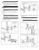
CAUTION: Contaminated water might cause decreased cooling capacity or disruption in service. The water flowing into the MCS unit must meet the guidelines stated in the HP Modular Cooling System G2 Site Preparation Guide. The MCS warranty does not cover damage caused by contaminated water. 7. Lower the unit by raising the two rear leveling feet on both the MCS unit and the rack so that the MCS unit can move freely on the remaining casters. 8.
11. Cap the unused side of each T-fitting on the MCS unit using the cap wrench. 14. Plug the network cable into the RJ-45 connector on the power inlet box. 12. Route the two drain hoses to the drain collection system catch basin. 15. Plug the other end of the network cable to your network connection. a. Install and route the blue drain hose into either the condensation return line or the gravity drain collection system catch basin. b.
17. If you are using a secondary power cord, plug it into the power connector on the right. Powering up and configuring the unit WARNING: To reduce the risk of electric shock or damage to the equipment: 18. 19. Guide the other ends of the power cords through the MCS unit, and then plug them into an appropriate power source. (Optional) Secure the two brackets to the MCS frame using two M6 trilobe flathead screws. 20. (Optional) Align the access panel with the two brackets. 21.
b. In the password field, enter the password. The default password is Admin. The Main Menu screen appears. 7. a. From the Main Menu screen, enter 1 Network Configuration. The Menu Network Configuration screen appears. Enter the product ID and serial number. The product ID and 10digit serial number are located on a label inside the rear MCS unit door. b. Enter 1 IP Configuration. The IP Configuration screen appears. a. From the Main Menu screen, enter 3 Factory Default.
b. Enter 4 Activate Actual Values. c. 10. 13. Click Setup>Accounts, and then change the default Web Admin and Web User passwords. 14. Click Save Settings. 15. (Optional, but recommended) Click Setup>Management>Remote Access, select SSL Enable. 16. (Optional) Enter an SSL key. 17. Click Save Settings. 18. To set up your trap receivers, click Setup>Management>Trap Receivers. 19. Click Save Settings. To reboot, enter y at the prompt.
20. (Optional, but recommended) To set up your SNMP managers, click Setup>Management>SNMP Managers. 4. Click Setup>Network. a. Select the radio button to disable DHCP (enabled is the default setting). b. Click Save Settings. c. Change the IP address in the IP Address field of the management module. d. Change the network mask of the management module. e. Change the default gateway of the management module. f. Click Save Settings. g. Log in to the new IP address. 21. Click Save Settings.
. (Optional) Enter an SSL key. Automatic Door Release Kit To view the HP Automatic Door Release hardware installation instructions, see the documentation that shipped with that kit. To enable the automatic door release functionality: 10. Click Save Settings. 11. To set up your trap receivers, click Setup>Management>Trap Receivers. 12. Click Save Settings. 13. (Optional, but recommended) To set up your SNMP managers, click Setup>Management>SNMP Managers. 14. Click Save Settings.
Legal notices © Copyright 2007 Hewlett-Packard Development Company, L.P. The information contained herein is subject to change without notice. The only warranties for HP products and services are set forth in the express warranty statements accompanying such products and services. Nothing herein should be construed as constituting an additional warranty. HP shall not be liable for technical or editorial errors or omissions contained herein. Microsoft and Windows are U.S.