HP Modular Cooling System Web Interface User Guide Part Number 403358-002 February 2007 (Second Edition)
© Copyright 2006, 2007 Hewlett-Packard Development Company, L.P. The information contained herein is subject to change without notice. The only warranties for HP products and services are set forth in the express warranty statements accompanying such products and services. Nothing herein should be construed as constituting an additional warranty. HP shall not be liable for technical or editorial errors or omissions contained herein. Confidential computer software.
Contents Overview..................................................................................................................................... 5 Introduction .............................................................................................................................................. 5 Web interface requirements .............................................................................................................. 5 Web interface .............................................
Replaceable parts and maintenance and service information ........................................................... 55 Replaceable parts ................................................................................................................................... 55 Acronyms and abbreviations........................................................................................................ 56 Index.................................................................................................
Overview In this section Introduction ............................................................................................................................................. 5 Introduction The HP Modular Cooling System has a management module with a web interface that analyzes, queries, and manages various measurements, and warning and alarm messages from the MCS unit.
Web interface In this section Using the web interface ............................................................................................................................ 6 Home tab ................................................................................................................................................ 8 Logs tab ................................................................................................................................................
• Main frame—Contains the various web interface screens based on the menu option selected in the left navigation frame. Active Alarms and Legend display panel Each tab in the web interface contains an Active Alarms and Legend display panel. When the MCS unit experiences a critical, warning, normal, unknown, or informational event, the icon corresponding to the event appears in the Active Alarms display panel. The alarm descriptions appear in the Alarms menu, as well as in the Alarm History menu.
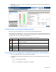
where hostname is the IP address of the management module and port number is the port number if using a port other than the default 80 for http and 443 for https. The login screen appears. 3. Log in through the web browser. Logging in through the web interface 1. Enter the user name in the User Name field. The default user name is Admin. 2. Enter the password in the Password field. The default password is Admin. NOTE: Passwords are case-sensitive. 3. Click Sign In.
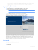
• Identification menu Overview menu Click Overview in the left navigation frame to display the Overview screen. This screen displays graphic meters for temperature and cooling system parameters.
Parameter Function Magnetic Door Lock Status Displays the door lock status Cooling Module 1, 2, and 3 • OK means the door lock is functioning properly and the door magnet is engaged. • Doors Released means there is an emergency door condition and the door magnet has released the doors. Displays the Server Intake and Server Exhaust temperature and the RPM of each cooling unit Alarms menu Click Alarms in the left navigation frame to display the Alarms screen.
Indicators Meaning Actual operator display alarm message Top, Mid, or Bot Fan Mod. Failed Actual web interface alarm message Top, Mid, or Bottom Fan Module Failed Condition Top, middle, or bottom fan module tach is less than its minimum rpm Module Top, middle, or bottom fan module SNMP notification Warning Type of message Warning Solution: 1. Remove the fan unit. 2. Reinstall the same fan unit.
Indicators Meaning Sensors HEX1, HEX2, or HEX3 sensors (this is the water to air heat exchanger unit temperature of the intake to the servers) SNMP notification Warning Type of message Warning Solution: 1. Remove the fan unit. 2. Remove the HEX unit. 3. Reinstall the same HEX unit. 4. Reinstall the same fan unit. If the warning message does not clear after the module is reseated, replace the HEX unit with a CSR part.
Solution: 1. View the Overview menu to distinguish which temperature sensor is different from the other temperature sensors. 2. After discovering which temperature sensor is not working properly, remove that module and reinstall it. If the difference is in the Server Exhaust Temperature, replace the appropriate fan unit. If the difference is in the Server Intake Temperature, replace the appropriate HEX unit.
Indicators Meaning Actual operator display alarm message Water Temp. Out Failed Actual web interface alarm message Water Unit Temperature Output Out of Range Condition Water temperature sensor is not working properly (possible open circuit) Sensors Water group sensor SNMP notification Warning Type of message Warning Solution: 1. Verify the water supply. 2. Verify whether the water temperature is below or above the water temperature expected range. 3. Contact your building supervisor. 4.
1. Verify the water valve is closed. 2. Contact HP, or see the HP website (http://www.hp.com). Leak detector sensor is not working properly Indicators Meaning Actual operator display alarm message Leak detector? Actual web interface alarm message Leak detector Failed Condition Leak detector sensor is not working properly Sensors Leak detector sensor SNMP notification Warning Type of message Warning Solution: Contact HP, or see the HP website (http://www.hp.com).
Solution: 1. Verify the water inlet temperature. 2. Verify that the flow matches the specifications required for heat load. 3. Adjust the temperature assigned in the web interface Intake Temp tab High Temperature Threshold field.
Indicators Meaning Actual web interface alarm message Temperature too low Condition Average server air temperature is lower than the temperature assigned in the web interface Intake Temp tab (on page 24) Low Temperature Threshold field Sensors Air temperature sensor SNMP notification Warning Type of message Warning Solution: 1. Verify water flow matches specifications required for heat load. 2. Verify whether the water temperature is below the expected range. 3.
Indicators Meaning Actual web interface alarm message Emergency Door Opening due to Water Flow Loss (0 l/min; 36/34/35°C) (0 gal/min; 97/93/95°F) Note: The interface alarm message displays the temperatures of the top, middle, and bottom fans so you can see which temperature has been exceeded and caused the alarm to trip. Condition The Water Flow Loss Emergency Door Opening Temperature Threshold has been exceeded or the water flow is less than 2 l/min (.5283 gal/min).
3. Adjust the temperature in the Server Intake Temperature Set Point or the Water Flow Loss Emergency Door Opening Temperature Threshold fields to prevent false alarms. IMPORTANT: Use caution when entering temperatures in the Emergency Door Opening fields. Setting the temperature thresholds too low might cause the MCS unit to shut down.
IMPORTANT: Use caution when entering temperatures in the Condensation Pump Threshold fields. Be sure to determine the proper default settings to prevent false alarms, without masking problems with the MCS. Default settings will vary, depending on the humidity level of your data center and the heat load generated by the equipment in the MCS. NOTE: A 24-hour clock starts when the condensation pump runs for the first time in more than 24 hours.
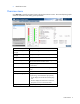
Parameter Value System Contact Displays information entered in the Setup>Management>System Information>System Contact field System Location Displays information entered in the Setup>Management>System Information>System Location field MAC Address Displays the MAC address IP Address Displays information entered in the Setup>Network>IP Address field Software Version Displays the software version Firmware Version Displays the firmware version Hardware Version Displays the hardware version Produc
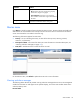
On the Event Log screen: • (Admin only) Click Clear Alarm History to clear the log files. This function clears all of the log files, and there is no way to recover the data after it is cleared. • Click Refresh to update the screen with current log information. Event Log menu Click Event Log in the left navigation frame to display the Event Log screen. The events are listed by the date and time at which the event most recently occurred.
On the Event Log screen: • (Admin only) Click Clear Event Log to clear the log files. This function clears all of the log files, and there is no way to recover the data after it is cleared. • Click Refresh to update the screen with current log information.
Intake Temp tab This screen enables the Admin to change server intake temperature settings for the management module. To change the server intake temperature settings: 1. Enter a server intake temperature set point in the Server Intake Temperature Set Point field. 2. Enter a temperature range in which the server intake temperature can vary in the Hysteresis Value field. 3.
NOTE: A 24-hour clock starts when the condensation pump runs for the first time in more than 24 hours. A warning is issued if either the cycle threshold or pump running time is exceeded within the 24-hour window. The clock stops and the counters are reset to zero for warning purposes if the thresholds are not exceeded within 24 hours after the last time the condensation pump runs. 10. 11. 12. Select to enable or disable the alarm relay from the Alarm Relay radio buttons.
Remote Access tab This screen enables the Admin to enter information for remote access to the management module. To enable SSL: 1. Select to enable SSL using the SSL radio button. 2. Click Save Settings. A new HTTPS URL appears on the operator display. 3. Log in to the web interface using the new IP address or hostname (using the https://hostname[:port number] format). 4. Enter the port number to use HTTPS in the HTTPS Port field.
2. Enter the port number to use HTTP in the HTTP Port field. 3. Do one of the following: o Click Save Settings to save the information. o Click Cancel to undo the changes. To configure other remote access settings: 1. Select to enable or disable FTP using the FTP radio buttons. 2. Enter the number of minutes for the HTTP/Console Session Timeout field. The default is 30 minutes. 3. Do one of the following: o Click Save Settings to save the information. o Click Cancel to undo the changes.
c. Click Next. The Certificate Store screen appears. d. Select Automatically select the certificate store based on the type of certificate, and click Next. e. Click Finish. A message appears, asking for verification of the root store. f. Click Yes. • Proceed without importing the certificate by clicking Yes at the Security Alert window. You continue to receive the Security Alert each time you log in until you import the certificate. Your data is still encrypted.
Alarms/Warnings tab This screen enables the Admin to change alarm and warning settings for the management module. To change the alarm and warning settings: 1. 2. 3. Select to enable or disable the alarm relay from the Alarm Relay radio buttons. This setting affects all alarms and warnings, except for the Server Intake Temperature. o Select Enable to allow the alarm relay when a temperature alarm is generated. o Select Disable to not allow the alarm relay when a temperature alarm is generated.
load? warning appears in the operator display, and a Heat Load Warning appears in the web interface. Setting the value to 0 disables the warning. When the MCS unit is in Auto mode, the Fan Speed Target and Water Valve fields are not available. On the Advanced screen, the administrator can change the temperature control modes for the management module. IMPORTANT: Temperature Control Manual mode is for service and troubleshooting only and is not to be used in a production environment.
o Click Save Settings to save the information o Click Door Opening Test to open the MCS front and rear doors and test the magnetic locks. o Click Cancel to undo the changes. Timers tab This screen enables the Admin to change timer settings for the management module. Timers are used to disable particular trap receivers on different days at different times of the week. To change the timer settings: 1. Select to enable or disable the timer control from the Timer Control radio buttons. 2.
General menu Click General in the left navigation frame to display the General screen. This screen enables the Admin to configure general management module parameters. To change the general parameters: 1. Enter a date in the Date field. (If NTP is enabled in the Network menu, do not enter a date in this field.) 2. Enter a time in the Time field. (If NTP is enabled in the Network menu, do not enter a date in this field.) 3. Select a date format from the Date Format dropdown box. Use MM/DD/YYYY for U.S.
o Click Clear Alarms to clear the alarms. NOTE: To clear the condensation pump cycles warning, click Cooling System in the left navigation frame to access the Cooling System screen, and then click the Alarms/Warnings tab. Under the Warnings section, set Alarm Reset to Manual and click Save Settings. Then, return to the General menu and click Clear Alarms. This step only clears the warning when the condensation pump is not running. 11.
NOTE: When DHCP is enabled, the IP Address, Network Mask, and Default Gateway fields are not available. 1. Select to enable or disable NTP from the Network Time Protocol (NTP) radio buttons. 2. If you enable NTP: a. Enter the IP address of the primary NTP server in the Primary NTP Server field. b. Enter the IP address of the secondary NTP server in the Secondary NTP Server field.
System Information tab This screen enables the Admin to enter contact information for the management module. The information entered on this screen appears on the Identification screen and is included with SNMP traps sent by the management module. To enter the contact information: 1. Enter the name of the management module in the System Name field. 2. Enter the name of the contact person in the System Contact field. 3. Enter the name of the location in the System Location field. 4.
To receive traps in HP SIM, see "Systems Insight Manager integration (on page 49)." To configure which servers should receive traps: 1. Select to enable or disable SNMP authentication traps from the Authentication Traps radio buttons. 2. Select to enable up to four SNMP traps from the Trap Receivers 1 through 4 radio buttons. 3. Enter the IP address for up to four trap recipients in the IP Address fields. 4. To save the settings, choose one of the following options: 5.
The SNMP manager entries do not have any effect on sending traps. To configure SNMP managers: 1. Enter the IP address for each SNMP manager in the IP Address field. 2. Do one of the following: o Click Save Settings to save the information. o Click Cancel to undo the changes. Accounts menu Click Accounts in the left navigation frame to access the Accounts screen. This screen enables the Admin to modify web and FTP Admin and User passwords and Serial Console Admin passwords.
• Serial Console Administrator (Admin)—Has full privileges to all of the serial console menu items To modify a password: 1. Enter the new password in the Setting field. 2. Enter the new password again in the Retype field. 3. Do one of the following: o Click Save Settings to save the updated account information. o Click Cancel to undo the changes. Configuration Save/Restore menu Click Configurations Save/Restore in the left navigation frame to access the Configuration Save/Restore screen.
• Click Restore Configuration to restore the configuration file. • Click Undo Changes to undo the changes. You can save the configuration and then restore the same configuration on multiple management modules. The IP address must be set individually on each unit through DHCP or the serial interface before the replication can be performed. To replicate a configuration to multiple MCS units, save the configuration file: 1. Configure the settings through the web interface. 2.
Contents menu Click Contents in the left navigation frame to display the Contents menu. This menu provides a list of the links to help topics.
Overview page Click Overview in the left navigation frame to display the Overview page. This page displays overview information about the product.
Index menu Click Index in the left navigation frame to display the Index menu. This menu provides a list of the links to help topics.
Upgrading the firmware In this section Upgrading the HP Modular Cooling System firmware................................................................................. 43 Upgrading the HP Modular Cooling System firmware The MCS unit must have the latest firmware to work properly. To upgrade the firmware: 1. Access the HP website (http://www.hp.com). 2. Click Software & Driver Downloads. 3. Ensure that the Download drivers and software (and firmware) option is selected. 4.
Cooling performance parameter settings In this section Cooling performance parameter settings overview ..................................................................................... 44 Cooling performance parameter settings overview The MCS unit has several cooling performance parameter settings. These settings control the fan speed and water flow to meet the rack-mounted component's cooling needs.
Parameter Function Warning Temperature Threshold Used to issue a warning if the warning temperature threshold temperature is exceeded Low Temperature Threshold Used to issue a warning if the low temperature threshold temperature is exceeded Water Flow Loss Emergency Door Opening Temperature Threshold Used to open the MCS doors when the temperature threshold is exceeded and water loss is detected This value cannot be lower than 5°C (9°F) above or more than 20°C (36°F) above the Server Intake Temperatu
IMPORTANT: Temperature Control Manual mode is for service and troubleshooting only and is not to be used in a production environment.
Example Server intake temperature Server exhaust temperature Top 24.5°C (76.1°F) 38.8°C (101.8°F) Middle 24.8°C (76.6°F) 39.1°C (102.4°F) Bottom 25.1°C (77.2°F) 40.3°C (104.5°F) Average 24.8°C (76.6°F) 39.4°C (102.9°F) Cooling air flow supplied by the MCS unit Delta temperature is used to determine and control the speed of the rotating fans.
• If the server intake temperature is above the Server Intake Temperature Set Point, the water valve opens (if not already opened) and cold water enters the heat exchanger units. • If the server intake temperature is below or equal to the Server Intake Temperature Set Point minus the Hysteresis value, the water valve closes (if not already closed). • If the server intake temperature is between the Hysteresis value, the water valve remains unchanged from its previous state.
Systems Insight Manager integration In this section Systems Insight Manager overview ........................................................................................................... 49 Discovering the management module ....................................................................................................... 49 Configuring HP SIM to receive traps.........................................................................................................
1. Locate the additionalwsdisc.props file in the CONFIG directory in the Systems Insight Manager install directory. By default, Systems Insight Manager is installed in the C:\Program Files\HP\System Insight Manager directory. 2. Create a management module entry in the additionalwsdisc.props file. For more information on editing the additionalwsdisc.props file, see the additionalwsdisc.txt file located in the same directory. Example: The additionalwsdisc.
Configuring the management module to send traps to HP SIM 1. Add the HP SIM server as an SNMP trap recipient on the Trap Receivers tab (on page 35). 2. Configure the management module to send alert notifications to HP SIM.
Security considerations In this section Security considerations overview.............................................................................................................. 52 Security considerations overview The management module implements strict security for two important reasons: • The module manages devices that have the potential to perform operations that are sensitive and destructive. • The management module has browser accessibility.
Frequently asked questions In this section Frequently asked questions ...................................................................................................................... 53 Frequently asked questions Question Answer How many user sessions are supported at one time? Only one user session is supported at a time. Sessions can be terminated if a second session is initiated or if a console session timeout occurs.
Question Answer Why are my event.log and The event.log and alarm.log are not formatted to be downloaded alarm.logs not formatted correctly in .bin mode. Use ASCII mode. when I download them in .bin mode? Is there a confirmation that my system No, there is no confirmation that the system is being restarted.
Replaceable parts and maintenance and service information In this section Replaceable parts .................................................................................................................................. 55 Replaceable parts The heat exchanger units and fan units are replaceable during real-time operation. Other unit parts are also replaceable. For more information on replaceable parts and CSR parts, refer to Technical support.
Acronyms and abbreviations CSR Customer Self Repair DHCP Dynamic Host Configuration Protocol DST daylight savings time FTP file transfer protocol GMT Greenwich mean time HTTP hypertext transfer protocol HTTPS hypertext transfer protocol secure sockets IP Internet Protocol MCS modular cooling system NTP network time protocol SNMP Simple Network Management Protocol SSL Secure Sockets Layer Acronyms and abbreviations 56
Index A accessing the management module 7 Advanced tab 29 Air temperature sensor failed 10 alarm and warning messages 10 Alarm History menu 21 Alarms menu 10 B browser security alert 27 C Communication failure 10 Configuration Save/Restore 38 Contents menu 40 Control Mode 46 cooling 44 cooling air flow 47 cooling performance parameters 44 Cooling System menu 23 HEX temperature out failed (Server Exhaust Temperature failed) 10 Home tab 8 I Identification menu 20 Index screen 42 Intake Temp tab 24 introdu
signing in through the web management interface 8 SNMP settings 51 SNMP trap notifications, setting up 49, 50 SSL browser security alert 27 Systems Insight Manager 49 Systems Insight Manager, overview 49 T tab, Advanced 29 tab, Help 39 tab, Home 8 tab, Intake Temp 24 tab, Logs 21 tab, Setup 23 tab, Trap Receivers 35, 50, 51 temperature 46, 47, 48 Temperature above threshold (Warning Temperature Threshold field) 10 Temperature below threshold (Low Temperature Threshold field) 10 Trap Receivers tab 35, 50, 5