HP Moonshot Switch User and Maintenance Guide Abstract This document is for the person who installs, administers, services, and troubleshoots switches. This guide provides identification, setup, installation, and removal procedures. HP assumes you are qualified in these areas.
© Copyright 2013 Hewlett-Packard Development Company, L.P. The information contained herein is subject to change without notice. The only warranties for HP products and services are set forth in the express warranty statements accompanying such products and services. Nothing herein should be construed as constituting an additional warranty. HP shall not be liable for technical or editorial errors or omissions contained herein.
Contents Component and LED identification .................................................................................................. 5 Chassis front panel LEDs and buttons ........................................................................................................... 5 Moonshot-6SFP Uplink Module .................................................................................................................... 6 Uplink module components ..................................................
Troubleshooting resources ........................................................................................................................ 32 Illustrated parts catalog ............................................................................................................... 33 Customer self repair................................................................................................................................. 33 Parts only warranty service .......................................
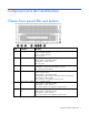
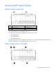
Component and LED identification Chassis front panel LEDs and buttons Item Description LED Status 1 Chassis power LED Flashing Green = The chassis is waiting to power on. Green = Normal operation Amber = Standby operation Off = No power 2 Chassis health LED Green = Normal operation Flashing Amber = Degraded condition Flashing Red = Critical condition Off = No power 3 Chassis UID LED/button Blue = Chassis ID is selected. Flashing blue = System firmware update is in process.
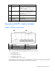
Moonshot-6SFP Uplink Module Uplink module components Item Component Description 1 Serial console port For management 2 SFP+ ports X1–X6 1Gb or 10Gb Ethernet SFP+ ports X1 through X6 support Ethernet traffic only. SFP+ ports support the following pluggable Ethernet transceiver modules: • HP 1000BASE-T SFP • HP 10GBASE-SR SFP+ • HP 10GBASE-DAC SFP+ Any available port can be used to connect to the data center.
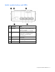
Item Description Status 1 Uplink module UID LED/button Solid blue = Switch module ID is selected. Flashing blue = Switch module firmware update is in progress. Off = Switch module ID is not selected.
Uplink module buttons and LEDs Item Description Status 1 Uplink module UID LED/button Solid blue = Switch module ID is selected. Flashing blue = Switch module firmware update is in progress. Off = Switch module ID is not selected.
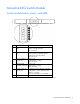
Moonshot-45G Switch Module Switch module button, sensor, and LEDs Item Description Status 1 Switch module power Green = Normal operation LED Amber = Standby operation Off = No power 2 Switch module health Green = Normal operation LED Flashing amber = Degraded condition Flashing red = Critical condition Off = No power 3 Switch module uplink Green = Link activity LED Flashing green = Activity Off = No activity 4 Switch module Green = Link downlink activity LED Flashing green = Activity Off = No act
Moonshot-180G Switch Module Switch module button, sensor, and LEDs Item Description Status 1 Switch module power Green = Normal operation LED Amber = Standby operation Off = No power 2 Switch module health Green = Normal operation LED Flashing amber = Degraded condition Flashing red = Critical condition Off = No power 3 Switch module uplink Green = Link activity LED Flashing green = Activity Off = No activity 4 Switch module Green = Link downlink activity LED Flashing green = Activity Off = No ac
iLO CM management port The iLO CM management port provides communication with the switch service port interface and is used for remote sessions. All service port traffic is routed through the iLO/MGMT port, located on the iLO CM module: The switch service port interface is enabled by default and can be used with the switch serial console port when making configuration changes. The switch serial console port is on the uplink module.
Operations Extend the chassis from the rack 1. Pull down the quick release levers on each side of the chassis. 2. Extend the chassis from the rack until it locks once. 3. Press the push tab on the rail, and then fully extend the chassis. WARNING: To reduce the risk of personal injury or equipment damage, be sure that the rack is adequately stabilized before extending a component from the rack. 4.
Remove the access panel IMPORTANT: After performing a procedure inside the chassis, always install the access panel on the chassis when complete. Do not operate the chassis for long periods of time with the access panel removed. 1. Release the access panel latch. 2. Slide the access panel back about 1.5 cm (0.5 in). 3. Lift and remove the access panel.
NOTE: Turn the access panel over to locate the hood labels. These labels provide information on installing various options, flexible memory configurations, LED status indicators, and switch settings. Open the cable management arm To open, lift the cable management arm up as you swing it open. Remove the uplink module blank Remove the component as indicated.
Remove the switch module blank Remove the component as indicated.
Setup Installation information and guidelines Before installing the module, review the following: • Always install the switch module and the uplink module in corresponding bays. Both components must be installed for normal operation. • The switch module and the uplink module can be installed in any order. • The switch module and the uplink module power down when either module is removed from the chassis.
Uplink module bays The uplink module can be installed in the uplink module bays located in the rear of the chassis. Installing the uplink module IMPORTANT: To avoid connectivity loss, do not remove any network cables or uplink modules already in operation. 1. Remove the uplink module bay blank.
2. Prepare the uplink module for installation. 3. Install the uplink module. 4. Do one of the following: o If the switch module is already installed, verify the uplink module powers on and the health LED is green. o If the switch module is not installed, install the switch module before verifying LEDs. For more information, see the "Installation information and guidelines (on page 16)." 5. After both components have been installed, verify the switch firmware is at the recommended firmware version.
3. Locate the switch module slot and remove the blank. 4. Prepare the switch module for installation.
5. Align and install the switch module into the chassis. 6. Do one of the following: o If the uplink module is already installed, verify the switch module powers on and the health LED is green. o If the uplink module is not installed, install the uplink module before verifying LEDs. For more information, see "Installation information and guidelines (on page 16)." 7. Install the access panel. 8. Install the chassis in the rack. 9.
Configuration Configuring the switch To configure the switch, see the Switch Administrator's Guide and the Switch CLI Command Reference in the HP Moonshot Information Library (http://www.hp.com/go/moonshot/docs).
Network mapping Production network mapping The first network interface discovered by the operating system routes traffic through switch A. The second network interface discovered by the operating system routes traffic through switch B.
Management network mapping All traffic from the service port management interface is routed through the iLO CM management port (on page 11). Interfaces Interfaces are identified by the switch CLI using a unit/slot/port naming convention. For more information on interface naming, see the Switch Administrator's Guide and the Switch CLI Command Reference in the HP Moonshot Information Library (http://www.hp.com/go/moonshot/docs).
Item Port Interface 1 X1 1/1/1 2 X2 1/1/2 3 X3 1/1/3 4 X4 1/1/4 5 X5 1/1/5 6 X6 1/1/6 Interfaces 1/1/1–1/1/6 are the uplink ports that connect to the datacenter.
Moonshot-45G downlink interfaces Interfaces 1/0/1–1/0/45 are the downlinks to the cartridge nodes. Each SoC is identified as a cartridge node. The iLO CM firmware identifies each node as cxny, where c is the cartridge and n is the node. Switch interfaces correspond to cartridge nodes, respectively. For example, c28n1 corresponds to cartridge 28, node 1, and interface 1/0/28.
Moonshot-180G downlink interfaces Interfaces 1/0/1–1/0/180 are the downlinks to the cartridge nodes. Each SoC is identified as a cartridge node. The iLO CM firmware identifies each node as cxny, where c is the cartridge and n is the node. Switch interfaces correspond to cartridge nodes, respectively.
Command Line Interface Connect to the switch console To manage the switch, use one of the following ports to connect to the switch console: • • • • Service port: o Out-of-band management o Over TCP/IP o Connect through the iLO CM management port ("Obtaining the switch management IP address" on page 28) Network port: o Inband management o Over TCP/IP o Connect through the network interface Serial console port: o Out-of-band management o Serial o Connect to the serial console port ("Acce
o 3. No flow control Start the terminal. The switch login prompt appears. 4. Enter: admin No password is set by default. Obtaining the switch management IP address To access the switch console remotely, be sure network connectivity is established with the iLO CM management port (on page 11). If DHCP services are provided on the network, obtain the switch management IP address: 1. Access the switch CLI interface locally. 2. Enter privileged exec mode. At the switch prompt, enter: enable 3.
o o o show firmware revisions show switch power show switch temperature To set switch power or switch UID LED: o o set switch power {off|on} {sa|sb|sa-b} set switch uid {off|on} {sa|sb|sa-b} To connect to the switch console using the virtual serial port: connect switch vsp {sa|sb} If the virtual serial port is not configured, configure the virtual serial port before connecting to the switch console: 1. 2.
Firmware Update the switch firmware Switch firmware can be updated using the following CLIs: • The iLO CM firmware CLI • The switch CLI To perform updates from the iLO CM firmware CLI, see the HP Moonshot iLO Chassis Management CLI User Guide in the HP Moonshot Information Library (http://www.hp.com/go/moonshot/docs). Switch updates are found on the HP Moonshot Component Pack download site (http://www.hp.com/go/moonshot/download).
update cpld The CPLD update reloads the switch and completes when the switch returns to an operational state. If no CPLD update is found, the update is not performed. 13. (Optional) Make a backup of the image: copy primary alternate This step overwrites the previous firmware version. Before committing, be sure no plans exist to downgrade switch firmware.
Troubleshooting Troubleshooting resources The HP Moonshot System Troubleshooting Guide provides procedures for resolving common problems and comprehensive courses of action for fault isolation and identification, issue resolution, and software maintenance on the HP Moonshot System. The document is available in the HP Moonshot Information Library (http://www.hp.com/go/moonshot/docs).
Illustrated parts catalog Customer self repair HP products are designed with many Customer Self Repair (CSR) parts to minimize repair time and allow for greater flexibility in performing defective parts replacement. If during the diagnosis period HP (or HP service providers or service partners) identifies that the repair can be accomplished by the use of a CSR part, HP will ship that part directly to you for replacement.
Switch customer self repair components Item Description Spare part number Customer self repair (on page 33) 1 HP Moonshot-45G Switch Module 712675-001 Mandatory1 2 HP Moonshot-180G Switch Module 712692-001 Mandatory1 3 HP Moonshot-4QSFP+ Uplink Module 712694-001 Mandatory1 4 HP Moonshot-6SFP Uplink Module 712676-001 Mandatory1 5 Switch module bay blank* 726173-001 Mandatory1 6 Uplink module bay blank* 745288-001 Mandatory1 * Not shown 1 Mandatory—Parts for which customer self re
Removal and replacement procedures Removing the switch module CAUTION: Be sure to save the running-configuration of the switch before removing any switch components. CAUTION: To avoid connectivity loss, do not remove switches already in operation. CAUTION: For proper cooling, be sure every switch module bay and uplink module bay has either a blank or a module installed. To remove the switch module: 1. Extend the chassis from the rack (on page 12). 2. Remove the access panel (on page 13). 3.
CAUTION: For proper cooling, be sure every switch module bay and uplink module bay has either a blank or a module installed. 1. Open the cable management arm (on page 14). 2. Remove the component as indicated.
Regulatory information Safety and regulatory compliance For safety, environmental, and regulatory information, see Safety and Compliance Information for Server, Storage, Power, Networking, and Rack Products, available at the HP website (http://www.hp.com/support/Safety-Compliance-EnterpriseProducts). Turkey RoHS material content declaration Ukraine RoHS material content declaration Warranty information HP ProLiant and X86 Servers and Options (http://www.hp.
Electrostatic discharge Preventing electrostatic discharge To prevent damaging the system, be aware of the precautions you need to follow when setting up the system or handling parts. A discharge of static electricity from a finger or other conductor may damage system boards or other static-sensitive devices. This type of damage may reduce the life expectancy of the device. To prevent electrostatic damage: • Avoid hand contact by transporting and storing products in static-safe containers.
Specifications Chassis environmental specifications Specification Value Temperature range* — Operating 10°C to 35°C (50°F to 95°F) Non-operating -30°C to 60°C (-22°F to 140°F) Maximum Wet bulb temperature — Operating 28ºC (82.4ºF) Non-operating 38.7ºC (101.7ºF) Relative humidity (noncondensing)** — Operating 10% to 90% Non-operating 5% to 95% * All temperature ratings shown are for sea level. An altitude derating of 1°C per 304.8 m (1.8°F per 1000 ft) to 3048 m (10,000 ft) is applicable.
Support and other resources Before you contact HP Be sure to have the following information available before you call HP: • Technical support registration number (if applicable) • Product name • Chassis serial number • Product identification number • Applicable error messages • Operating system type and revision level To obtain product information, log in to iLO CM firmware and use the Show Chassis Info command.
Acronyms and abbreviations CM chassis management CMU HP Insight Cluster Management Utility CPLD complex programmable logic device CSR Customer Self Repair DAC direct attach cable DHCP Dynamic Host Configuration Protocol ESD electrostatic discharge ID identification MAC Media Access Control QSFP quad small form-factor pluggable QSFP+ enhanced quad small form-factor pluggable SCP Secure Copy Protocol Acronyms and abbreviations 41
SFP+ enhanced small form-factor pluggable SFTP Secure File Transfer Protocol SoC system on chip SR short range SSH Secure Shell TFTP Trivial File Transfer Protocol UID unit identification VSP virtual serial port Acronyms and abbreviations 42
Documentation feedback HP is committed to providing documentation that meets your needs. To help us improve the documentation, send any errors, suggestions, or comments to Documentation Feedback (mailto:docsfeedback@hp.com). Include the document title and part number, version number, or the URL when submitting your feedback.
Index A G access panel 13 activity LED 5 administration 21 authorized reseller 40 guidelines, installation 16 guidelines, troubleshooting 32 B health LED 5, 9 HP contact information 40 HP technical support 40 before you contact HP 40 blank, removal 14, 15 buttons 35 C cable management arm 14 chassis, extend from rack 12 CLI (Command Line Interface) 27 CLI, accessing 27, 28 compliance 37 components 5, 33, 34 components, identification 5, 33 components, uplink module 6, 7 configuration 21 contact infor
series number 37 setup 16 spare part numbers 33 static electricity 38 support and other resources 40 switch firmware, updating 30 switch health LEDs 5, 9 switch module bay numbering 16, 17 switch module, configuring 21 switch module, installing 17, 18 T technical support 40 troubleshooting 32 U updating firmware 28, 30 uplink module 6, 8, 17 uplink module bay identification 16, 17 uplink module components 6, 7 uplink module, configuring 21 uplink module, installing 17 uplink module, removing 35 W warrant