HP Moonshot iLO Chassis Management Web Interface User Guide Abstract This guide provides information about configuring, updating, and operating HP Moonshot Systems by using the Moonshot iLO Chassis Management web interface. This document is intended for system administrators, HP representatives, and HP Authorized Channel Partners who are involved in configuring and using HP Moonshot Systems.
© Copyright 2012, 2014 Hewlett-Packard Development Company, L.P Confidential computer software. Valid license from HP required for possession, use or copying. Consistent with FAR 12.211 and 12.212, Commercial Computer Software, Computer Software Documentation, and Technical Data for Commercial Items are licensed to the U.S. Government under vendor's standard commercial license. The information contained herein is subject to change without notice.
Contents 1 Introduction to the HP Moonshot iLO Chassis Management web interface..........5 Overview................................................................................................................................5 HP Moonshot iLO CM firmware web interface features..................................................................5 Moonshot web interface............................................................................................................
Saving the event log...........................................................................................................61 Clearing the event log........................................................................................................62 Using the iLO CM IML.............................................................................................................62 Viewing the IML..........................................................................................................
1 Introduction to the HP Moonshot iLO Chassis Management web interface Overview The Moonshot iLO Chassis Management web interface allows GUI-based aggregated chassis management on the HP Moonshot System. The interface runs on the iLO CM firmware version 1.30 and later, and provides access to many of the same functions available from the iLO CM firmware command line.
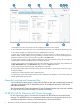
1. HP Moonshot main menu: The primary menu for navigating to resources. Click to expand. 2. View customization menus: Filters your view to only the desired components. Also available to customize log views. 3. View selector: Enables you to select the information displayed about a resource. 4. Actions menu: Provides the actions that are available to run on the current resource. Actions include, but are not limited to: adding, creating, deleting, removing, and editing a resource instance.
For more information about the HP RESTful API see the following website: http://www.hp.com/ go/restfulinterface/docs.
2 Setting up a Moonshot System Overview The default settings enable you to use most features without additional configuration. However, the configuration flexibility of iLO CM firmware enables customization for multiple enterprise environments. This chapter references the initial iLO CM setup steps. Complete the initial setup steps: 1. Install the Moonshot System in a data center. For more information, see the HP Moonshot 1500 Chassis Setup and Installation Guide available at http://www.hp.
Data center production network To connect the chassis to a production network, connect to any available SFP+ or QSFP+ port. The SFP+/QSFP+ ports are located on the uplink module installed in the rear of the chassis.
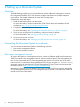
Setting up Moonshot by using the Moonshot iLO CM firmware web interface You can use the iLO CM firmware web interface to configure the Moonshot System if you can connect to the web interface on the network with a web browser. Access the iLO CM firmware web interface from a remote network client by using a supported browser to access the hostname and then entering a user name and password.
3 Using the web interface to view Moonshot System details This chapter provides information about viewing the available information using Moonshot web interface. Using the iLO CM firmware web interface You can use the iLO CM firmware web interface to manage the HP Moonshot System. You can also use the iLO CM firmware command line. Browser support The iLO CM firmware web interface requires a browser that supports JavaScript. For a list of supported browsers, see Table 1 (page 11).
Viewing overview information Viewing Moonshot general information From the main menu, select Chassis to display high level information about the chassis. It includes general chassis information and reference images of the chassis, along with cartridge health and node power gauges. Viewing the Chassis top view From the main menu, select Chassis to view chassis cartridge and switch information.
• ◦ Critical—Service lost or imminent service loss, immediate attention needed ◦ Unknown Cartridge number NOTE: Click the cartridge number link to open the Cartridges page and display specifics about the installed cartridge. For more information, see Viewing ProLiant server cartridge information. • Cartridge name (model) • CPU number and architecture • UID control—click this icon to turn the cartridge UID on or off. • ◦ UID is off. Click the icon to turn the UID on. ◦ UID is on.
• • UID control—click this icon to turn the switch UID on or off. ◦ UID is off. Click the icon to turn the UID on. ◦ UID is on. Click the icon to turn the UID off. Switch power control—This icon simulates the physical power button on the switch. Click the icon to turn the switch on or off. ◦ The switch is off. ◦ The switch is on. Viewing the chassis back view From the main menu, select Chassis to view basic chassis fan and power supply information using the back view.
The Cartridge Health gauge shows the health of all cartridges. The gauge is divided into cartridges that have critical issues, issues that cause degraded performance, and cartridges that are OK (have no issues). • Critical • Degraded • OK The Node Power State gauge displays the total number of nodes in the Moonshot 1500 Chassis, and how many are powered on and off. • Nodes that are off. • Nodes that are on.
Selecting multiple cartridges To select multiple cartridges from the cartridge list, do one of the following: • Hold Ctrl and click each cartridge to be selected. • Click Select all. • Click a cartridge to select it, hold Shift, and then click another cartridge to select all the cartridges between the two selections. Viewing Moonshot cartridge overview information From the main menu, select Cartridges to view cartridge overview information.
The System Firmware section displays the version information for the following firmware installed on the selected cartridge: • System ROM firmware • CPLD • Satellite firmware • Cartridge data The Mezzanine section displays information about any accessory cards attached to the server cartridge. If present, the information can include the following for each mezzanine attachment: • Model—The model name of attached accessory. • Serial number—The serial number of the attached accessory.
From the main menu, select Cartridges to view the Cartridges page. The page defaults to an overview of the first cartridge in the list of all available cartridges, shown on the left side of the page. Select Logs from the View menu to show the cartridge logs. The Log information available for each cartridge includes the following: • ID—The event ID number. Events are numbered in the order in which they are generated. By default, the Event Log is sorted by the ID, with the most recent event at the top.
• Select a preset range or a date range in the Created on menu. • To search for events based on dates, event IDs, or description text, enter text in the Search box, and then press Enter. • Click Reset filters to set the filters back to the default values.
1. Click Actions→View CSV. The Moonshot Event Log CSV for the cartridge is displayed. 2. Click Save or click Close to close the window. Clearing the cartridge IML Users with the Operator privilege can clear a cartridge IML of all previously logged information. To clear a cartridge IML: 1. Click Actions→Clear Log. The following message appears: All log entries for this device will be deleted. This action cannot be undone. Continue with clearing the log? 2. Click Yes.
The Thermal table displays the following information for the selected cartridge: • Sensor—The ID of the temperature sensor, which also gives an indication of the sensor’s location. • Status—The temperature status of the cartridge. Depending on the server cartridge configuration, some sensors show a status of Not installed. • Current Reading—The temperature recorded by the listed temperature sensor. If a temperature sensor is not installed, the Current Reading column shows the value N/A.
Customizing the node list You can customize which nodes are displayed in the node list by using the node filter menus. A selected filter is bold. Click a bold entry again to deselect it. Customize the node list by doing one or more of the following: • Select a power state from the System Power menu. • Select a health status from the Server health menu. • Select a boot source from the Boot options menu. • Click the Reset filters link to start over with the default selections.
The Node status section displays the following: • Power—The node power status. ◦ The node is off. ◦ The node is on. The Node Details section displays the following: • Processor family—The architecture of the processor. • Number of cores—The number of processing cores in the node. • Max clock speed—The maximum operating speed of the node cores expressed in MHz. • Total memory—The amount of permanent system memory available to the node expressed in GB.
1. Click Actions→Boot options. The Select boot options page displays. 2. In the Select boot order section, select the following: 3. 4. 5. 24 • Boot device 1—The primary device to seek on boot. • Boot device 2—The secondary, or backup, device to seek on boot if the primary device is not present or contains no boot instructions. In the Select boot once section, select a device to seek on boot for the next boot only. Boots subsequent to the next boot revert back to the Boot device 1 and 2 settings.
Changing the power state of a node To change the power state of a node: 1. Select one or more nodes. 2. The available selections depend on the current state of the selected nodes. Do one of the following: • Click Actions→Power off Node (Shutdown) to gracefully exit the running operating system and power off the node. • Click Actions→Power off Node (Force) to power off the node when an OS is not installed. • Click Actions→Power On Node to power on the selected node.
Customizing the node log view You can customize which log entries are displayed as follows: 26 • To filter by severity, select a severity level from the Severity menu. The selection is cumulative; and you can select more than one severity level. A selected severity level is bold. Click a bold entry again to deselect it. • Select a preset range or a date range in the Created on menu.
Saving a node event log To save the node event log as a CSV file: 1. Select Actions→View CSV. The node event log is displayed in a format that you can copy and paste into a text editor. 2. 3. Click Save, and then follow the browser prompts to save or open the file. Click Close to close the window. Clearing a node event log Users with the Administrator privilege can clear logs of all previously logged information. To clear a node event log: 1. Select Actions→Clear Log.
• Product ID—The product ID of the switch. This value is set by the manufacturer, but can be changed by an Administrator using the iLO CM firmware command line if the switch is replaced. • Serial number—The serial number of the switch. This value is assigned when the switch is manufactured, but can be reset by an Administrator using the command line if the server cartridge is replaced. • Manufacturing date—The date and time the switch was built.
Changing the state of a switch’s UID 1. 2. Select the check box next to either Switch A or Switch B. You cannot select both switches at once. The available actions depend on the current state of the selected switch. NOTE: No selections are available in the Actions menu until a switch is selected. Do one of the following: • Select Actions→UID on to turn on the UID of the selected switch. • Select Actions→UID off to turn off the UID of the selected switch.
Customizing the switch log view You can customize which log entries are displayed as follows: • To filter by severity, select a severity level from the Severity menu. The selection is cumulative; and you can select more than one severity level. A selected severity level is bold. Click a bold entry again to deselect it. • Select a preset range or a date range in the Created on menu. • To search for events based on dates, event IDs, or description text, enter text in the Search box, and then press Enter.
3. Click Save or click Close to close the window. Clearing a switch log Users with the Administrator privilege can clear switch logs of all previously logged information. To clear a switch log: 1. Select the check box next to either Switch A or Switch B. You cannot select both switches at once. 2. Select Actions→Clear Log. The following message appears: All log entries for this device will be deleted. This action cannot be undone. Continue with clearing the log? 3. Click Yes.
The Thermal table displays the following information for each switch: • Sensor—The ID of the temperature sensor, which also gives an indication of the sensor’s location. • Status—A health icon showing the current sensor status. Depending on the switch configuration, some sensors show a status of Not installed. • Current Reading—The current temperature reported by the sensor. • Thresholds—The temperature thresholds for the warning for overheating conditions.
• Satellite—The satellite firmware version. • Data—The switch data file version. Cartridges This section displays the following information about the installed HP ProLiant server cartridges: • Bay—The slot location of the cartridge. • Product name—The model name of the cartridge. • System ROM—The ProLiant series server ROM version. • Satellite—The cartridge satellite firmware version. • Data—The server cartridge data firmware version.
The Power Supplies section displays the following: • Bay—The bay number of the power supply. • Status—The status of the power supply. • Model—The model name of the power supply. • Capacity—The capacity of the power supply (watts). • Present Power Reading—The amount that the power supply is consuming, measured in watts. • Serial—The serial number of the power supply. • Spare—The part number of the spare power supply. • Firmware—The installed power supply firmware.
• ◦ Critical—Service lost or imminent service loss, immediate attention needed ◦ Disabled or Not installed—Service is unavailable or the component is not present. ◦ Unknown—A detected health problem cannot be classified Speed—The percentage of maximum speed at which the fan is currently running. Viewing temperature information The Temperatures page displays the status, current reading, threshold settings, and temperature meter values for temperature sensors in the chassis.
The Temperatures page displays the following information: • Sensor—The ID of the temperature sensor, which also gives an indication of the sensor location. • Status—The temperature status. • Current Reading—The temperature recorded by the listed temperature sensor. If a temperature sensor is not installed, the Current Reading column shows the value N/A. • Thresholds—The temperature thresholds for the warning for overheating conditions. The two threshold values are Caution and Critical.
The following information is listed for each session: • User—The login name used to log in to the session. • IP—The IP address of the computer used to log in to the session. • Login Time—The date and time that the session started. • Access Time—The date and time that the Moonshot 1500 CM module was last accessed by the listed session. • Expires—The date and time that the session will expire. • Source—The method used to initiate the session (for example, web interface or SSH).
4. Click Yes to continue, or click Cancel. If you disconnected the current session, the browser returns to the login page. If you disconnected a remote session, the following message appears: Active Session(s) successfully disconnected. Viewing the time settings SNTP allows the iLO CM firmware to synchronize its clock with an external time source. To view the time settings, select Time Settings in the main menu.
4 Configuring Moonshot System This chapter includes procedures for configuring a Moonshot System by using the iLO CM firmware web interface. Updating firmware Firmware updates enhance functionality with new features, improvements, and security updates. Updating Moonshot firmware From the main menu, select Firmware Update to view the firmware update page. Updating HP Moonshot System firmware keeps it up to date with the latest features and enhancements.
HP Moonshot Component Pack is a comprehensive firmware solution tested on the HP Moonshot System and delivered as a compressed file. The compressed file includes all the component files needed to update a Moonshot System. Deploy the firmware updates contained in the Moonshot Component Pack using the following tools: • iLO Chassis Manager CLI • Moonshot Web Interface • HP Moonshot Switch Module CLI • HP Smart Update Manager Download the latest pack from the HP website (http://www.hp.
such as c6–10, or multiple specific cartridges, such as c6,8,10. Enter all to upload a firmware file to all cartridges. • 6. Switches—Specify the switch. To target a single switch, enter sA, or sB. To target both switches, enter sA,B or sA-B. (Optional) For switch firmware updates, you must enable TFTP from the iLO CM firmware command line before the next step. Switch firmware updates require TFTP to copy the firmware update files to the switch.
Viewing local user accounts To view local user accounts, select User Administration from the main menu. The User Administration page shows the login name and full name of each user. To view the privileges for a user, select the user in the user list. The available privileges follow: • Administrator—An administrator has read and write access to all iLO CM firmware features. • Operator—An operator can perform system actions, but cannot configure the iLO CM firmware or manage user accounts.
3. Provide the following details: • Full name appears in the user list on the User Administration page. It does not have to be the same as the Login name. The Full name must use printable characters. • Login name is the name you use when logging in to the iLO CM firmware. It appears in the user list on the User Administration page and in logs. The Login name does not have to be the same as the Full name. The login name must use printable characters.
Password guidelines HP recommends that you follow these password guidelines: • The maximum password length is 39 characters. • Passwords can include any characters except for spaces. • The default minimum password length is 8 characters. Modify this with the set password minimum CLI command. For information about setting the password minimum value, see the HP Moonshot iLO Chassis Management CLI User Guide.
3. Enter the following information in the Information section: • Country (C)—The two-character country code that identifies the country where the company or organization that owns this HP Moonshot System is located. Enter the two-letter abbreviation in capital letters. • State (ST)—The state where the company or organization that owns this HP Moonshot System is located. • City or Locality (L)—The city or locality where the company or organization that owns this HP Moonshot System is located.
5. After a few minutes (up to 10), click Generate CSR again, or select Actions→View CSR on the SSL Certificate page. The CSR is displayed. The CSR contains a public and private key pair that validates communications between the client browser and iLO CM firmware. Key sizes up to 2,048 bits are supported. The generated CSR is held in memory until a new CSR is generated, the iLO CM firmware is reset to the factory default settings, or a certificate is imported. 6. 7. 8.
5. 6. 7. Select Browse local files or Copy into text box. This determines the method of inserting the certificate contents into the iLO CM firmware. • Browse local files—Select this option to load a certificate file stored on the local system. • Copy into text box—Select this option to paste the certificate text into a text box. Depending on the selected method, do one of the following: • Click Browse, and then select a certificate file.
3. Click Save to save the CSR text to a file. For information about using the CSR to obtain a trusted certificate, see “Obtaining a trusted SSL certificate” (page 44). Managing network settings Viewing general network information To view a summary of the configured network settings, select Network Configuration from the main menu.
The General section lists the following: • MAC address—The MAC address of the iLO CM management port on the Moonshot 1500 CM module. • Host name—The Moonshot 1500 CM module host name. This name serves as the host-specific label portion of the DNS name. • Domain name—The Moonshot 1500 CM module domain name. • FQDN—The fully-qualified Moonshot 1500 CM module DNS name.
1. From the main menu, select Network Configuration. The IPv4 summary section displays the DHCPv4 status, IPv4 address, Subnet mask, and Default gateway settings.
2. Select IPv4 in the View menu in the upper left corner of the page, or click the More link in the IPv4 summary section. The following information is displayed: • • • • • IPv4 address ◦ IPv4 address—The IPv4 address currently in use. If the value is 0.0.0.0, the IPv4 address is not configured. ◦ Subnet mask—The subnet mask of the IPv4 address currently in use. If the value is 0.0.0.0, no address is configured. ◦ Default gateway—The default gateway address in use for the IPv4 protocol.
Configuring IPv4 settings 1. 2. Select Network Configuration from the main menu. Select Actions→Edit. 3. Configure the following settings in the IPv4 section: 4. 52 • DHCPv4—Enables the Moonshot 1500 CM module to obtain its IP address (and many other settings) from a DHCP server. • IPv4 address—The Moonshot 1500 CM module IP address. If DHCP is used, this value is supplied automatically. If DHCP is not used, enter a static IP address.
5. Configure the following settings in the Advanced section: • Ping gateway on startup—Causes the iLO CM Firmware to send four ICMP echo request packets to the gateway when the Moonshot 1500 CM module initializes. This ensures that the ARP cache entry is up-to-date on the router responsible for routing packets to and from the Moonshot 1500 CM module. • Use DHCPv4 for—Select from the following check boxes to configure the values that will be provided by the DHCP server.
6. 7. 8. 9. ◦ WINS—Specifies whether the DHCP server-supplied WINS server list is used. If not, enter the WINS server addresses in the Primary WINS server and Secondary WINS server boxes in the WINS section. ◦ Static routes—Specifies whether the DHCP server-supplied static routes is used. If not, enter the static route destination, mask, and gateway addresses in the Static routes section.
Configuring the host name When you configure the Moonshot 1500 CM module host name, note the following limitations: • • Name service limitations—The host name is used as part of the DNS name. ◦ DNS allows alphanumeric characters and hyphens. ◦ Name service limitations also apply to the Domain name. Namespace issues—To avoid these issues: ◦ Do not use the underscore character. ◦ Limit host names to 15 characters.
5. Click Yes. A reset ends all active sessions. It might take several minutes before you can re-establish a connection. Configuring SNTP settings Viewing the time settings SNTP allows the iLO CM firmware to synchronize its clock with an external time source. To view the time settings, select Time Settings in the main menu. The following information is displayed: • Primary NTP server—The configured primary NTP server. • Secondary NTP server—The configured secondary NTP server.
3. Do one of the following: • Select the Configure using DHCPv4 check box to use a DHCP-provided NTP server address. NOTE: To configure a DHCPv4-provided NTP server, you must first enable DHCPv4 on the Network Configuration page. For more information, see “Managing network settings” (page 48). • 4. Enter NTP server addresses in the Primary NTP server and Secondary NTP server boxes. You can enter the server addresses by using the server FQDN or IPv4 address. Enter the NTP polling period.
6. Click Apply to save the changes. The following message appears: The chassis manager will automatically reset to apply the settings. Continue to apply the settings and reset the chassis manager? 7. Click Yes. A reset ends all active sessions. It might take several minutes before you can re-establish a connection. TIP: If you notice that event log entries have an incorrect date or time, make sure that the NTP server addresses and time zone are correct.
5 Working with events Using the iLO CM event log The event log provides a record of significant events recorded by the iLO CM firmware. Logged events include major events such as a power outage or system reset, and iLO CM firmware events such as firmware updates, configuration changes, and successful or unsuccessful browser and SSH logins. Viewing the event log To view the event log, select Event Log in the main menu. The log displays the following information: • ID—The event ID number.
• Last Update—The date and time when the latest event of this type occurred. This value is based on the date and time stored by the iLO CM firmware. For information about setting the time in the iLO CM firmware, see “Editing the time settings” (page 56). • Initial Update—The date and time when the first event of this type occurred. This value is based on the date and time stored by the iLO CM firmware.
• To filter by the Initial Update date, select a date range in the Initial Update menu. • To search for events based on dates, event IDs, or description text, enter text in the Search box, and then press Enter. • Click Reset filters to set the filters back to the default values. • Click a column heading to sort the event log table by that column. • When sorting the event log table by column, click the triangle next to the column heading to change the display to ascending or descending order.
3. 4. Click Save, and then follow the browser prompts to save or open the file. Click Close to close the window. Clearing the event log Users with the Administrator privilege can clear the event log of all previously logged information. To clear the event log: 1. From the main menu, select Event Log. 2. Select Actions→Clear Log. The iLO CM firmware notifies you that all log entries will be deleted, and that you cannot undo this action. 3. Click Yes.
• Switch insertion and removal • IML cleared Viewing the IML To view the IML, select Integrated Management Log in the main menu. The IML displays the following information: • The first column on the left side of the web interface displays a check box next to each event with Critical or Caution status. Use this check box to select an event to mark as repaired. For information about marking events as repaired, see “Marking an IML entry as repaired” (page 65). • ID—The event ID number.
• Initial Update—The date and time when the first event of this type occurred. This value is based on the date and time stored by the iLO CM firmware. • Count—The number of times this event has occurred (if supported). In general, important events generate an IML entry each time they occur. They are not consolidated into one event log entry. When less important events are repeated, they are consolidated into one IML entry, and the Count and Last Update values are updated.
• To filter by the Initial Update date, select a date range in the Initial Update menu. • To search for events based on dates, event IDs, or description text, enter text in the Search box, and then press Enter • Click Reset filters to set the filters back to the default values. • Click a column heading to sort the IML table by that column. • When sorting the IML table by column, click the triangle next to the column heading to change the display to ascending or descending order.
3. Select the log entry. To select an IML entry, click the check box next to the entry in the first column of the IML table. If a check box is not displayed next to an IML entry, that entry cannot be marked as repaired. 4. Select Actions→Mark Repaired. The iLO CM firmware web interface refreshes, and the selected log entry status changes to Repaired.
2. Select Actions→View CSV. The IML is displayed. 3. 4. Click Save, and then follow the browser prompts to save or open the file. Click Close to close the window. Clearing the IML Users with the Administrator privilege can clear the IML of all previously logged information. To clear the IML of all previously logged information: 1. From the main menu, select Integrated Management Log. 2. Select Actions→Clear Log.
6 Troubleshooting This chapter provides troubleshooting solutions for the Moonshot Web Interface. Bypassing a lost or forgotten administrator password HP Moonshot 1500 Chassis Management modules ship with default credentials, Administrator and password. Change these credentials after deployment, in accordance with good security practices. If user credentials are forgotten or lost, and no administrator access is available, use the security override switch located on the Moonshot 1500 CM module.
4. 5. Reinsert the Moonshot 1500 CM module and wait for it to boot. Connect to the Moonshot iLO CM firmware using a serial port or SSH. When the Login prompt displays, press Enter twice. WARNING! While the security override is toggled, anyone may log into the chassis manager as the Administrator because no password is required. Anyone accessing the Moonshot iLO CM firmware will see a security alert display after login. 6. Set up a new account or reset the password for the Administrator account.
9. Insert the Moonshot 1500 CM module. 10. Verify access to the Moonshot iLO CM firmware with the new username or password.
7 Support and other resources Information to collect before contacting HP Be sure to have the following information available before you contact HP: • Software product name • Hardware product model number • Operating system type and version • Applicable error message • Third-party hardware or software • Technical support registration number (if applicable) How to contact HP Use the following methods to contact HP technical support: • In the United States, see the Customer Service / Contact HP U
• HP Moonshot-45G Switch Administrator's Guide • HP Moonshot Component Pack Release Notes • HP Insight Cluster Management Utility v7.1 User Guide • HP Insight CMU v7.1 Getting Started Guide for Pre-Installed HP Moonshot 1500 Chassis Websites • HP Moonshot Information Library: http://www.hp.com/go/moonshot • HP Moonshot Component Pack download website: http://www.hp.com/go/servers/moonshot/download • Intel IPMI specification website: http://www.intel.com/design/servers/ipmi/tools.
NOTE: TIP: Provides additional information. Provides helpful hints and shortcuts.
8 Documentation feedback HP is committed to providing documentation that meets your needs. To help us improve the documentation, send any errors, suggestions, or comments to Documentation Feedback (docsfeedback@hp.com). Include the document title and part number, version number, or the URL when submitting your feedback.
Index A active iLO sessions disconnecting, 37 active sessions viewing, 36 authorized resellers, 71 B browser support web interface, 11 C certificate signing request viewing, 47 contacting HP, 71 conventions document, 72 D DHCP IPv4 settings, 52 disconnecting iLO sessions, 37 DNS name default value, 10 DNS servers IPv4, 52 document conventions, 72 documentation providing feedback on, 74 domain name configuring, 55 E event log clearing, 62 overview, 59 saving, 61 viewing, 59 HP technical support, 71 I i
network connection, 8 overview, 8 setting up Moonshot web interface, 10 SSL viewing certificates, 44 SSL certificates importing, 46 obtaining, 44 static routes IPv4, 52 subnet mask IPv4, 52 Support and other resources, 71 T technical support HP, 71 temperature information viewing, 35 typographic conventions, 72 U user accounts adding, 42 default user account, 10 editing, 42 overview, 41 privileges, 41 viewing, 42 W web interface browser support, 11 overview, 5 using, 11 WINS servers IPv4, 52 76 Index