
HP RPG/XL Programmer's Guide (30318-90001)
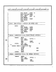
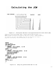

8-: 11
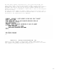
Comments
1 This line defines the USWITCH file.
Column 16 specifies that this file is a chained file.
Column 30 indicates that the key field length is 1.
2 This line defines the input USWITCH record.
3 This line (at the beginning of the program) turns on indicator
20. Indicator 20 triggers an update of the USWITCH file (U1 is
turned on).
4 This line reads a USWITCH record whenever indicator 20 or the
last record indicator (LR) are turned on.
5 This line describes the USWITCH output record that is written
when indicator 20 is turned on.
6 This line defines the user indicator settings that are written
to the USWITCH file when indicator 20 is turned on.
Columns 45-63 contain "USWITCH: 10XXXXXX" to specify the
settings for the user indicators. User indicator U1 is turned
on, U2 is turned off and the others remain unchanged.
7 This line defines the USWITCH output record that is written when
the LR indicator is turned on.
8 This line defines the user indicator settings that are written
to the USWITCH file at the end of the program.
Columns 45-63 contain "USWITCH: 01XXXXXX" to specify the
settings for the user indicators. User indicator U1 is turned
off, U2 is turned on and the others remain unchanged.
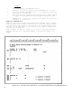
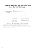
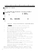
Using the System-Defined Job Control Word (JCW). The System-Defined Job
Control Word (JCW) is a two-byte data area that is part of the operating
system. It provides a way to pass indicators among operating system
routines. Application programs can use the rightmost byte of the JCW for
indicators. The rightmost byte provides up to eight User Switches, one
switch per bit. When these switches are used in RPG, they are called
user indicators (U1-U8).
The System-Defined JCW is easier to use than a USWITCH file. You do not
enter File Description and Input Specifications for the JCW and it is
updated automatically by RPG. The System-Defined JCW has one
disadvantage. Since the system software also uses it, you cannot always
count on switch values remaining unaltered. For more details on JCWs,
see the
MPE XL Intrinsics Reference Manual
.
Figure 8-7 shows the structure of the System-Defined JCW.