
Configuring and Managing Host-Based X.25 Links - Edition 5 (36939-90054)

122 Chapter6
Configuring X.25 Links Step-by-Step
Modify the Network Management Configuration File
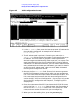
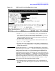
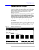
Figure 6-5 X.25 Configuration Screen
1. In the IP address field, enter the internet protocol (IP) address for
the node being configured. An example of an address is:
C 192.191.191 009
2. The IP subnet mask is optional. If entering one, tab to the IP
subnet mask field and enter the number in the same format as an
IP address. The 32-bit mask is grouped in octets expressed as
decimal integers and delimited by either a period (.) or a space. The
mask identifies which bits of an IP address will be used to define a
subnetwork. To determine these bits, you first need to estimate how
many subnetworks and nodes per subnetwork you need. For details
on deriving an IP subnet mask, refer to the HP 3000/iX Network
Planning and Configuration Guide.
3. Move to the first Link Name field. Enter a link name to represent
the DTC/X.25 Network Access card for which you are configuring a
link. This name must be unique to both the node and the DTC. The
link name must be the same as the link name configured for this
card on the DTC X.25 Card Configuration — Sys-to-Sys LUGs screen
during the DTC configuration see Chapter 3, “Configuring DTCs
Step-by-Step.”
4. Enter the node name of the DTC that houses the DTC/X.25 Access
card in the first DTC Node Name field the enter the slot number of
the card in the Card Number field. Enter a link name, DTC node
name, and card number for each link you are configuring.
5. When you are done adding links, press the
[Save Data] key.