
MPE/iX System Utilities Reference Manual (32650-90908)

Chapter 25
STANDARDS
The initial system loader
210
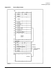
Main Memory Layout
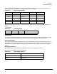
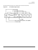
Although the exact memory locations of boot and IPL code during the boot process vary according to size of
the IODC and IPL, a general description of memory layout is presented here for clarification. Also, the first
page of main memory is reserved for communication between PDC and software.
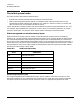
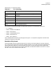
The format of the first memory controller configuration is as follows:
• word0: HPA of the memory controller
• word1: SPA of the corresponding memory
• word2: SPA_size
• word3: Max_Mem
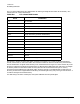
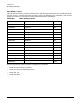
Table 25-8 Main memory layout
X'00000000 Initalize vectors 0
X'00000040 Processor dependent 64
X'00000200 Reserved 512
X'00000350 Memory configuration 848
X'00000360 MEM_ERR 864
X'00000380 MEM_FREE 896
X'00000384 MEM_HPA 900
X'00000388 MEMPDC 904
X'0000038C MEM_10MSEC 908
X'00000390 Initial memory module 912
X'000003A0 Boot console/display 928
X'000003D0 Boot device 976
X'00000400 Boot keyboard 1024
X'00000430 Reserved 1072
X'00000600 Processor dependent 1536
X'00000800 2048