
NS3000/iX NMMGR Screens Reference Manual - Edition 8 (36922-90038)

42 Chapter3
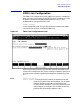
Link Configuration Screens
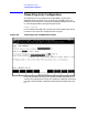
Link Configuration: LAP-B Link Data
Buffer size Layer 3 through 7 frame size. This is the amount of
data that a user of OSI Levels 3 through 7 can put in
that frame. It does not include Level 2 header or trailer
information. This parameter is used to configure
memory buffers.
Default value: 1024
Range: 32–1024 Bytes
Local mode If the node you are configuring is a Hewlett-Packard
computer operating across a point-to-point link, enter
11 (the default). HP computers at both ends of a
point-to-point link must both be configured as HP
point-to-point. If the remote node is a non-HP node and
the local station is acting as DTE, enter 5. If the remote
node is a non-HP node and the local station is acting as
DCE, enter 6. If the node you are configuring is DCE,
then the node at the other side must be DTE. If the
node you are configuring is DTE, then the node at the
other side must be DCE.
Default value: 11
Range: 5 = DTE, 6 = DCE, 11 = HP Point-to-Point
Transmission
speed This is the line-transmission speed in bits per second. It
may be overridden by whichever device is providing
clocking. The PSI simply transmits using the provided
clock source, whether it is the HP 3000’s CPU clock or a
modem.
Default value: 56000
Range: 1200, 2400, 4800, 9600, 19200, 38400, 56000, or
64000 bits/second
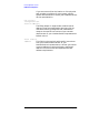
Trace at
startup (HP modifiable.) Enter Y (YES) to enable link tracing
at link startup, N (NO) otherwise. This value can be
overridden with the LINKCONTROL command.
If you do enable link tracing, you are required to enter a
trace file name. For best performance, do not enable
tracing.
Default value: N