
Installation manual


36
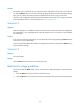
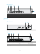
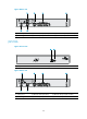
Figure 48 Rear view
(1) G.SHDSL port 0
(2) Ethernet WAN port (GE0)
(3) Ethernet L
A
N ports (GE1 to GE4)
(4) Grounding screw (5) Power adapter port (6) Console/AUX port
JG518A
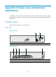
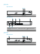
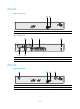
Figure 49 Front view
(1) USB port (2) Reset button
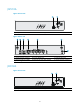
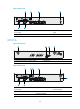
Figure 50 Rear view
(1) ADSL port 0 (2) Ethernet WAN port (GE0)
(3) Ethernet L
A
N ports (GE1 to GE4)
(4) Grounding screw (5) Power adapter port (6) Console/AUX port