
Installation manual


38
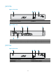
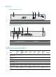
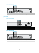
Figure 54 Rear view
(1) ADSL port 0 (2) Ethernet WAN port (GE0)
(3) Ethernet L
A
N ports (GE1 to GE4)
(4) Grounding screw (5) Power adapter port (6) Console/AUX port
JG520A
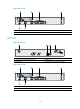
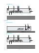
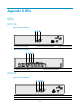
Figure 55 Front view
(1) 3G antenna auxiliary connector (DIV)
(2) USB port
(3) Reset button (4) 3G antenna main connector (MAIN)
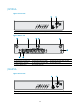
Figure 56 Rear view
(1) ADSL port 0 (2) Ethernet WAN port (GE0)
(3) Ethernet L
A
N ports (GE1 to GE4)
(4) Grounding screw (5) Power adapter port (6) Console/AUX port
1 2 3 4