HP mt40 Mobile Thin Client Maintenance and Service Guide IMPORTANT! This document is intended for HP authorized service providers only.
© Copyright 2012 Hewlett-Packard Development Company, L.P. Bluetooth is a trademark owned by its proprietor and used by Hewlett-Packard Company under license. Intel and Celeron are U.S. registered trademarks of Intel Corporation. Microsoft and Windows are U.S. registered trademarks of Microsoft Corporation. SD Logo is a trademark of its proprietor. The information contained herein is subject to change without notice.
Safety warning notice WARNING! To reduce the possibility of heat-related injuries or of overheating the device, do not place the device directly on your lap or obstruct the device air vents. Use the device only on a hard, flat surface. Do not allow another hard surface, such as an adjoining optional printer, or a soft surface, such as pillows or rugs or clothing, to block airflow. Also, do not allow the AC adapter to contact the skin or a soft surface, such as pillows or rugs or clothing, during operation.
iv Safety warning notice
Table of contents 1 Product description ........................................................................................................... 1 2 External component identification ..................................................................................... 5 Display ................................................................................................................................... 5 TouchPad ......................................................................................
Service tag ............................................................................................................. 27 Computer feet ......................................................................................................... 28 Battery ................................................................................................................... 29 Service cover ..........................................................................................................
8 Recycling ........................................................................................................................ 75 Index .................................................................................................................................
viii
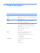
1 Product description Category Description Product Name HP mt40 Mobile Thin Client Processor Intel® Celeron® B840 1.90-GHz processor (1333-MHz FSB, 2.0-MB L3 cache, 35 W) Chipset Mobile Intel HM76 chipset Graphics Intel HD Graphics 4000 universal memory architecture (UMA) graphics with shared video memory Supports dual display ports through the dock Panel 14.
Category Description Optical drive Fixed Serial ATA 12.
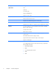
Category Description Ports ● 1394a port ● Audio-in (mono microphone) ● Audio-out (stereo headphone) ● Battery connector ● DisplayPort 1.1a ● Docking connector ● eSATA/USB 2.0 combo port ● HP Smart AC adapter ● RJ-45 (Ethernet) ● Secondary battery connector ● USB 3.0 ports (2) ● USB 2.0 port ● VGA Dsub 15 pin) supporting: 1920×1200 external resolution @ 75 Hz, hot plug and unplug and autodetection for correct output to wide-aspect vs.
Category Description Security (continued) Preboot authentication (password, Smart Card) Operating system Preinstalled: Microsoft® Windows® Enterprise System 7 Web-only support: Microsoft Windows Enterprise System 7 Serviceability 4 Chapter 1 Product description End user replaceable parts: ● AC adapter ● Battery ● Keyboard ● Memory module ● Optical drive ● Solid-state drive ● WLAN module
2 External component identification Display Content Component Content Component (1) Internal display switch (4) Webcam light (select models only) (2) WLAN antennas (2)* (5) Webcam (select models only) (3) Internal microphone(s) (1 without webcam/2 with webcam) *The antennas are not visible from the outside of the computer. For optimal transmission, keep the areas immediately around the antennas free from obstructions.
TouchPad NOTE: Your computer may look slightly different from the illustration in this section.
Front Content Component Content Component (1) Display release latch (4) Battery light (2) Wireless light (5) Drive light (3) Power light (6) Speakers (2) Content Component Content Component (1) Power connector (4) Media Card Reader (2) USB 3.
Right side Content Component Content Component (1) Audio-out (headphone) jack (5) DisplayPort (2) Audio-in (microphone) jack (6) Vents (2) (3) eSATA/USB 2.0 port (7) Security cable slot (4) USB 2.0 port *For information regarding the status of the USB port, contact your network administrator.
Bottom Content Component Content Component (1) Vents (4) (5) Battery bay (2) Battery release latch (6) Accessory battery connector (3) Docking connector (7) Bluetooth compartment (4) Service cover release latch (8) Service cover Bottom 9
3 10 Illustrated parts catalog Chapter 3 Illustrated parts catalog
Service tag When ordering parts or requesting information, provide the computer serial number and model number provided on the service tag. It is necessary to remove the battery to obtain these numbers. See Battery on page 34 for battery removal instructions. Item Description Function (1) Product name This is the product name affixed to the front of the computer. (2) Serial number (s/n) This is an alphanumeric identifier that is unique to each product.
Computer major components 12 Chapter 3 Illustrated parts catalog
Item Component Spare part number (1) Display assembly: The display assembly is spared at the subcomponent level only. For more display assembly spare part information, see Display assembly subcomponents on page 15.
Item Component Spare part number For use in the United States 701976-001 (3) Top cover (includes TouchPad and 2 TouchPad buttons): 684338-001 (4) Fan (includes cable) 641839-001 (5) Heat sink (includes replacement thermal material) 693371-001 (6) System board equipped with the Mobile Intel HM76 chipset and a graphics subsystem with UMA memory (includes replacement thermal material) 710658-001 (7) Speaker assembly (includes cable) 641840-001 (8) Intel Celeron B840 1.
Display assembly subcomponents Item Component Spare part number (1) Display bezel 685999-001 Display Hinge Cover Kit, includes: 642783-001 (2) Display hinge covers (3) Display Hinge Kit (includes left and right display hinges and left and right hinge brackets) 641836-001 (4) 14.
Item Component Spare part number Display Panel Support Kit (not illustrated, includes WLAN antenna cables and transceivers and display enclosure) 710654-001 Display Rubber Kit (not illustrated, includes display bezel rubber screw covers and display bezel rubber bumpers) 642785-001 Plastics Kit Item 16 Description Spare part number Plastics Kit, includes: 710656-001 (1) RJ-11 jack plug (2) ExpressCard slot space saver (3) Optical drive bay space saver Chapter 3 Illustrated parts catalog
Mass storage devices Item (1) Description Spare part number Hard Drive Hardware Kit, includes: 642774-001 Hard drive bracket Hard drive bracket screws (not illustrated) (2) DVD-ROM drive (includes optical drive bezel and optical drive bracket) 716387-001 (3) 16-GB SATA solid-state drive (does not include solid-state drive bracket or screws): 716388-001 Mass storage devices 17
Miscellaneous parts Component Spare part number AC adapter: 65-W HP Smart AC adapter (non-PFC, 3-wire) 693711-001 65-W HP Smart AC adapter (RC/V, EM, 3-wire) 693710-001 Power cord (3-pin, black, 1.
Sequential part number listing Spare part number Description 490371-001 Power cord for use in North America (3-pin, black, 1.83-m) 490371-011 Power cord for use in Australia (3-pin, black, 1.83-m) 490371-021 Power cord for use in Europe (3-pin, black, 1.83-m) 490371-031 Power cord for use in the United Kingdom and Singapore (3-pin, black, 1.83-m) 490371-081 Power cord for use in Denmark (3-pin, black, 1.83-m) 490371-111 Power cord for use in Switzerland (3-pin, black, 1.
20 Spare part number Description 664663-001 Intel Celeron B840 1.90-GHz processor for use only on HP ProBook 6470b Notebook PC computer models (1333-MHz, 2.0-MB L3 cache, 35 W; includes replacement thermal material) 669832-001 Broadcom 43228 802.
Spare part number Description 701976-271 Keyboard for use in Romania (includes keyboard cable) 701976-281 Keyboard for use in Thailand (includes keyboard cable) 701976-291 Keyboard for use in Japan (includes keyboard cable) 701976-A41 Keyboard for use in Belgium (includes keyboard cable) 701976-AB1 Keyboard for use in Taiwan (includes keyboard cable) 701976-AD1 Keyboard for use in South Korea (includes keyboard cable) 701976-B31 Keyboard for use in the Netherlands (includes keyboard cable) 7
4 Removal and replacement procedures Preliminary replacement requirements Tools required You will need the following tools to complete the removal and replacement procedures: ● Flat-bladed screw driver ● Magnetic screw driver ● Phillips P0 and P1 screw drivers Service considerations The following sections include some of the considerations that you must keep in mind during disassembly and assembly procedures.
Cables and connectors CAUTION: When servicing the computer, be sure that cables are placed in their proper locations during the reassembly process. Improper cable placement can damage the computer. Cables must be handled with extreme care to avoid damage. Apply only the tension required to unseat or seat the cables during removal and insertion. Handle cables by the connector whenever possible. In all cases, avoid bending, twisting, or tearing cables.
Grounding guidelines Electrostatic discharge damage Electronic components are sensitive to electrostatic discharge (ESD). Circuitry design and structure determine the degree of sensitivity. Networks built into many integrated circuits provide some protection, but in many cases, ESD contains enough power to alter device parameters or melt silicon junctions. A discharge of static electricity from a finger or other conductor can destroy static-sensitive devices or microcircuitry.
Packaging and transporting guidelines Follow these grounding guidelines when packaging and transporting equipment: ● To avoid hand contact, transport products in static-safe tubes, bags, or boxes. ● Protect ESD-sensitive parts and assemblies with conductive or approved containers or packaging. ● Keep ESD-sensitive parts in their containers until the parts arrive at static-free workstations. ● Place items on a grounded surface before removing items from their containers.
Equipment guidelines Grounding equipment must include either a wrist strap or a foot strap at a grounded workstation. ● When seated, wear a wrist strap connected to a grounded system. Wrist straps are flexible straps with a minimum of one megohm ±10% resistance in the ground cords. To provide proper ground, wear a strap snugly against the skin at all times. On grounded mats with banana-plug connectors, use alligator clips to connect a wrist strap.
Component replacement procedures This chapter provides removal and replacement procedures. There are as many as 84 screws that must be removed, replaced, and/or loosened when servicing the computer. Make special note of each screw size and location during removal and replacement. Service tag When ordering parts or requesting information, provide the computer serial number and model number provided on the service tag. It is necessary to remove the battery to obtain these numbers.
Computer feet The computer feet are adhesive-backed rubber pads. The feet are included in the Rubber Kit, spare part number 641831-001. There are four rectangular rubber feet (1) and three square rubber feet (2) that attach to the base enclosure and service cover in the locations illustrated below.
Battery Description Spare part number 9-cell, 100-Wh, 3.00-Ah 631243-001 6-cell, 62-Wh, 2.80-Ah 628668-001 Before disassembling the computer, follow these steps: 1. Turn off the computer. If you are unsure whether the computer is off or in Hibernation, turn the computer on, and then shut it down through the operating system. 2. Disconnect the power from the computer by unplugging the power cord from the computer. 3. Disconnect all external devices from the computer. Remove the battery: 1.
Service cover Description Spare part number Includes country of origin label 684326-001 Includes regional configure to order (RCTO) with “made in China” label 699324-001 Before removing the service cover, follow these steps: 1. Turn off the computer. If you are unsure whether the computer is off or in Hibernation, turn the computer on, and then shut it down through the operating system. 2. Disconnect the power from the computer by unplugging the power cord from the computer. 3.
Optical drive Description Spare part number DVD-ROM drive (includes an optical drive bezel and optical drive bracket) 716387-001 Before removing the optical drive, follow these steps: 1. Turn off the computer. If you are unsure whether the computer is off or in Hibernation, turn the computer on, and then shut it down through the operating system. 2. Disconnect the power from the computer by unplugging the power cord from the computer. 3. Disconnect all external devices from the computer. 4.
5. If it is necessary to replace the optical drive bracket, position the optical drive with the rear panel toward you. 6. Remove the two Phillips PM2.0×3.0 screws (1) that secure the optical drive bracket to the optical drive. 7. Remove the optical drive bracket (2). Reverse this procedure to reassemble and install the optical drive.
3. Remove the solid-state drive (3) from the solid-state drive bay. 4. If it is necessary to disassemble the solid-state drive, perform the following steps: a. Remove the four Phillips PM3.0×3.0 screws (1) that secure the hard drive bracket to the solid-state drive. b. Remove the hard drive bracket (2) from the solid-state drive. The hard drive bracket and screws are available in the Hard Drive Hardware Kit, spare part number 642774-001.
RTC battery Description Spare part number RTC battery (includes cable and double-sided tape) 651948-001 Before removing the RTC battery, follow these steps: 1. Turn off the computer. If you are unsure whether the computer is off or in Hibernation, turn the computer on, and then shut it down through the operating system. 2. Disconnect the power from the computer by unplugging the power cord from the computer. 3. Disconnect all external devices from the computer. 4.
Reverse this procedure to install the RTC battery. Memory module NOTE: Primary and expansion memory is installed in a stacked configuration in the bottom of the computer. Description Spare part number 4-GB memory module (PC3, 12800, 1600-MHz) 641369-001 Update BIOS before adding memory modules Before adding new memory, make sure you update the computer to the latest BIOS. CAUTION: Failure to update the computer to the latest BIOS prior to installing new memory may result in various system problems.
2. Remove the memory module (2) by pulling the module away from the slot at an angle. NOTE: Memory modules are designed with a notch (3) to prevent incorrect insertion into the memory module slot. NOTE: The computer uses two memory slots. The top slot houses the expansion memory module and is shown in the first image below. The bottom slot houses the primary memory module and is shown in the second image below. Reverse this procedure to install a memory module.
WLAN module Description Spare part number Broadcom 43228 802.11abgn 2×2 Wi-Fi Adapter 669832-001 CAUTION: To prevent an unresponsive system, replace the wireless module only with a wireless module authorized for use in the computer by the governmental agency that regulates wireless devices in your country or region. If you replace the module and then receive a warning message, remove the module to restore device functionality, and then contact technical support.
3. Remove the WLAN module (3) by pulling the module away from the slot at an angle. NOTE: WLAN modules are designed with a notch (4) to prevent incorrect insertion. NOTE: If the WLAN antennas are not connected to the terminals on the WLAN module, the protective sleeves must be installed on the antenna connectors, as shown in the following illustration. Reverse this procedure to install the WLAN module.
Fan Description Spare part number Fan (includes cable) 641839-001 Before removing the fan, follow these steps: 1. Turn off the computer. If you are unsure whether the computer is off or in Hibernation, turn the computer on, and then shut it down through the operating system. 2. Disconnect the power from the computer by unplugging the power cord from the computer. 3. Disconnect all external devices from the computer. 4. Remove the battery (see Battery on page 29). 5.
Keyboard For use in country/region Spare part number For use in country/region Spare part number For use in Belgium 701976-A41 For use in Northwest Africa 701976-FP1 For use in Bulgaria 701976-261 For use in Portugal 701976-131 For use in Canada 701976-DB1 For use in Romania 701976-271 For use in the Czech Republic and Slovakia 701976-A81 For use in Russia 701976-251 For use in Denmark 701976-081 For use in Saudi Arabia 701976-171 For use in France 701976-051 For use in Slovenia 7
Remove the keyboard: 1. Loosen the three Phillips captive screws that secure the keyboard to the computer. 2. Rest and secure the computer on its right side. 3. Partially open the computer. 4. Insert a screw driver or similar thin tool into the keyboard release opening in the battery bay, and then press on the back of the keyboard until the keyboard disengages from the computer. 5. Turn the computer right-side up with the front toward you.
6. Lift the rear edge of the keyboard, and then swing the keyboard up and forward until it rests upside down on the palm rest. 7. Release the zero insertion force (ZIF) connector (1) to which the keyboard cable is attached, and then disconnect the keyboard cable (2) from the keyboard. NOTE: The pointing stick cable is present on select models only. 8. Release the ZIF connector (3) to which the pointing stick cable is attached, and then disconnect the pointing stick cable (4) from the system board. 9.
Base enclosure Description Spare part number Base enclosure (includes seven rubber feet, the service cover release latch assembly, and the battery release latch assembly) 687224-001 Before removing the base enclosure, follow these steps: 1. Turn off the computer. If you are unsure whether the computer is off or in Hibernation, turn the computer on, and then shut it down through the operating system. 2. Disconnect the power from the computer by unplugging the power cord from the computer. 3.
44 5. Remove the four Phillips PM2.5×3.0 screws from the battery bay (4) that secure the base enclosure to the computer. 6. Remove the two Phillips PM2.5×3.0 screws (1) from the hard drive bay that secure the base enclosure to the computer. 7. Remove the three Phillips PM2.0×3.0 screws (2) from the optical drive bay that secure the base enclosure to the computer. 8. Position the computer with the battery bay toward you.
9. Remove the four Torx TM2.5×8.0 screws from the rear panel of the computer. 10. Remove the wireless cables from the clips (1) and routing channel built into the base enclosure. 11. Disconnect the speaker cable (2) from the system board.
12. Remove the base enclosure by lifting it straight up from the computer. NOTE: Thoroughly clean the thermal pad material from the surfaces of the base enclosure (1) and the PCH chip (2) each time you remove the base enclosure. All base enclosure and system board spare part kits include replacement thermal pad material. Reverse this procedure to install the base enclosure.
Speaker assembly Description Spare part number Speaker assembly (includes cable) 641840-001 Before removing the speaker assembly, follow these steps: 1. Turn off the computer. If you are unsure whether the computer is off or in Hibernation, turn the computer on, and then shut it down through the operating system. 2. Disconnect the power from the computer by unplugging the power cord from the computer. 3. Disconnect all external devices from the computer. 4.
3. Remove the speaker assembly (2) from the base enclosure. Reverse this procedure to install the speaker assembly. Service cover release latch assembly NOTE: The service cover release latch assembly components are included in the Latch Kit, spare part number 684339-001. Before removing the service cover release latch assembly, follow these steps: 1. Turn off the computer.
2. Remove the service cover release latch actuator from the base enclosure. 3. Turn the base enclosure right side up, with the front toward you. 4. Remove the service cover release latch arm spring from the spring retention hooks on the service cover release latch arm (1) and the base enclosure (2). 5. Slide the service cover release latch arm (1) as far to the left as it will go. 6.
7. Lift the left end of the service cover release latch arm (3) out of the openings in the base enclosure. 8. Swing the left end of the service cover release latch arm (1) toward the back of the computer. 9. Release the right end of the service cover release latch arm (2) from the openings in the base enclosure. 10. Remove the service cover release latch arm. Reverse this procedure to install the service cover release latch assembly.
Battery release latch assembly NOTE: The battery release latch assembly components are included in the Latch Kit, spare part number 684339-001. Before removing the battery release latch assembly, follow these steps: 1. Turn off the computer. If you are unsure whether the computer is off or in Hibernation, turn the computer on, and then shut it down through the operating system. 2. Disconnect the power from the computer by unplugging the power cord from the computer. 3.
52 4. Remove the battery release latch arm spring from the spring retention hooks on the base enclosure (1) and the battery release latch arm (2). 5. Slide the battery release latch arm (1) as far to the right as it will go. 6. Lift the right end of the battery release latch arm (2) until it is clear of the retention post built into the base enclosure. 7. Swing the right end of the battery release latch arm (3) clockwise until it is clear of the retention post built into the base enclosure. 8.
9. Swing the right end of the battery release latch arm (2) clockwise until the left end of the arm release from the openings in the base enclosure. 10. Remove the battery release latch arm. Reverse this procedure to install the battery release latch assembly.
NOTE: When replacing the system board, be sure that the following components are removed from the defective system board and installed on the replacement system board: ● Memory module (see Memory module on page 35) ● WLAN module (see WLAN module on page 37) ● Heat sink (see Heat sink on page 56) ● Processor (see Processor on page 58) Remove the system board: 54 1. Position the computer right-side up, with the front toward you. 2. Open the computer. 3.
9. Disconnect the display panel cable (5) from the system board. 10. Remove the four Phillips PM2.5×5.0 screws that secure the system board to the top cover. 11. Lift the right side of the system board (1) until it rests at an angle.
12. Remove the system board (2) by sliding it up and to the right at an angle. Reverse this procedure to install the system board. Heat sink Description Spare part number Heat sink (includes replacement thermal material) 693371-001 Before removing the heat sink, follow these steps: 56 1. Turn off the computer. If you are unsure whether the computer is off or in Hibernation, turn the computer on, and then shut it down through the operating system. 2.
g. Base enclosure (see Base enclosure on page 43) h. System board (see System board on page 53) Remove the heat sink: 1. Following the 1, 2, 3, 4 sequence stamped into the heat sink, loosen the four captive Philllips screws (1) that secure the heat sink to the system board. 2. Remove the heat sink (2). NOTE: Due to the adhesive quality of the thermal material located between the heat sink and the system board components, it may be necessary to move the heat sink from side to side to detach it.
Reverse this procedure to install the heat sink. Processor NOTE: The processor spare part kit includes replacement thermal material. Description Spare part number Intel Celeron B840 1.90-GHz processor (1333-MHz FSB, 2.0-MB L3 cache, 35 W; includes replacement thermal material) 664663-001 Before removing the processor, follow these steps: 58 1. Turn off the computer.
h. System board (see System board on page 53) i. Heat sink (see Heat sink on page 56) Remove the processor: 1. Use a flat-bladed screw driver (1) to turn the processor locking screw one-half turn counterclockwise, until you hear a click. 2. Lift the processor (2) straight up, and remove it. NOTE: The gold triangle (3) on the processor must be aligned with the triangle icon (4) embossed on the processor socket when you install the processor. Reverse this procedure to install the processor.
Display assembly NOTE: The display assembly is spared at the subcomponent level only. For more display assembly spare part information, see the individual removal subsections. Before removing the display assembly, follow these steps: 1. Turn off the computer. If you are unsure whether the computer is off or in Hibernation, turn the computer on, and then shut it down through the operating system. 2. Disconnect the power from the computer by unplugging the power cord from the computer. 3.
4. Remove the top cover (3) from the display assembly. 5. If it is necessary to replace the display bezel or any of the display assembly subcomponents: a. Remove the rubber screw covers (1). The rubber screw covers are available in the Display Rubber Kit, spare part number 642785-001. b. Remove the two Phillips PM2.5×5.0 screws (2) that secure the display bezel to the display assembly. c.
d. Remove the display bezel (4). The display bezel is available using spare part number 685999-001. 6. If it is necessary to replace the webcam/microphone module: CAUTION: Handle the webcam/microphone module with caution. The module has a thin profile and is susceptible to damage when not handled carefully. 62 a. Detach the webcam/microphone module (1) from the display enclosure. (The webcam/ microphone module is attached to the display enclosure with double-sided tape.) b.
c. Remove the webcam/microphone module (3). The webcam/microphone module is available using spare part number 684346-001. The microphone module is available using spare part number 642797-001. 7. If it is necessary to replace the display panel: a. Remove the eight Phillips PM2.5×4.0 screws (1) that secure the display panel to the display enclosure. b. Lift the top edge of the display panel (2) until the display panel rests at an angle. c. Remove the display panel (3).
8. If it is necessary to replace the display hinge covers: a. Remove the two Phillips PM2.5×3.0 screws (1) that secure the display hinge covers to the display hinges. b. Slide the display hinge covers (2) toward each other to remove them from the display hinges. The display hinge covers are available using spare part number 642783-001. 9. If it is necessary to replace the display hinges: a. Remove the four Phillips PM2.5×3.0 screws (1) that secure the display hinges to the display enclosure. b.
10. If it is necessary to replace the display panel cable: CAUTION: Before turning the display panel upside down, make sure the work surface is clear of tools, screws, and any other foreign objects. Failure to follow this caution can result in damage to the display panel. a. Turn the display panel upside down, with the display panel cable toward you. b. Release the adhesive support strip (1) that secures the display panel cable to the display panel. c.
c. Remove the WLAN antenna cables and transceivers (3). The WLAN antenna cables and transceivers are included in the Antenna Kit, spare part number 642799-001. Reverse this procedure to reassemble and install the display assembly.
5 Computer Setup (BIOS) and Advanced System Diagnostics Using Computer Setup Computer Setup, or Basic Input/Output System (BIOS), controls communication between all the input and output devices on the system (such as disk drives, display, keyboard, mouse, and printer). Computer Setup includes settings for the types of devices installed, the startup sequence of the computer, and the amount of system and extended memory. NOTE: Use extreme care when making changes in Computer Setup.
NOTE: You can use either a pointing device (TouchPad, pointing stick, or USB mouse) or the keyboard to navigate and make selections in Computer Setup. 2. Press f10 to enter Computer Setup. To exit Computer Setup menus, choose one of the following methods: ● To exit Computer Setup menus without saving your changes: Click the Exit icon in the lower-left corner of the screen, and then follow the on-screen instructions.
Updating the BIOS The next sections describe different ways of updating the BIOS. Downloading SoftPaqs to update the BIOS Most BIOS updates on the HP website are packaged in compressed files called SoftPaqs. To install BIOS updates from the HP website, follow the steps below: 1. Download the SoftPaq from the HP website. 2. Click Run, and then follow the on-screen instructions to update the BIOS. NOTE: Some download packages contain a file named Readme.
Using Advanced System Diagnostics Advanced System Diagnostics allows you to run diagnostic tests to determine if the computer hardware is functioning properly. The following diagnostic tests are available in Advanced System Diagnostics: ● Start-up test—This test analyzes the main computer components that are required to start the computer. ● Run-in test—This test repeats the start-up test and checks for intermittent problems that the start-up test does not detect.
6 Specifications Computer specifications Metric U.S. Width 33.80 cm 13.31 in Depth 23.13 cm 9.11 in Height (front to back) 3.40 to 3.60 cm 1.34 to 1.42 in Equipped with 9-cell battery, optical drive, graphics subsystem with UMA memory, one memory module, WLAN module, solid-state drive, and TouchPad 2.47 kg 5.45 lbs Equipped with 9-cell battery, graphics subsystem with UMA memory, one memory module, WLAN module, solid-state drive, and TouchPad 2.33 kg 5.
Metric U.S. Operating 5°C to 35°C 41°F to 95°F Nonoperating -20°C to 60°C -4°F to 140°F Relative humidity (noncondensing) Operating 10% to 90% Nonoperating 5% to 95% Maximum altitude (unpressurized) Operating -15 m to 3,048 m -50 ft to 10,000 ft Nonoperating -15 m to 12,192 m -50 ft to 40,000 ft NOTE: Applicable product safety standards specify thermal limits for plastic surfaces. The device operates well within this range of temperatures. 14.0-inch SGA display specifications Metric U.S.
7 Power cord set requirements The wide-range input feature of the computer permits it to operate from any line voltage from 100 to 120 volts AC, or from 220 to 240 volts AC. The 3-conductor power cord set included with the computer meets the requirements for use in the country or region where the equipment is purchased. Power cord sets for use in other countries and regions must meet the requirements of the country or region where the computer is used.
Requirements for specific countries and regions 74 Country/region Accredited agency Applicable note number Australia EANSW 1 Austria OVE 1 Belgium CEBC 1 Canada CSA 2 Denmark DEMKO 1 Finland FIMKO 1 France UTE 1 Germany VDE 1 Italy IMQ 1 Japan METI 3 The Netherlands KEMA 1 Norway NEMKO 1 The People's Republic of China COC 5 South Korea EK 4 Sweden SEMKO 1 Switzerland SEV 1 Taiwan BSMI 4 The United Kingdom BSI 1 The United States UL 2 1.
8 Recycling When a non-rechargeable or rechargeable battery has reached the end of its useful life, do not dispose of the battery in general household waste. Follow the local laws and regulations in your area for battery disposal. HP encourages customers to recycle used electronic hardware, HP original print cartridges, and rechargeable batteries. For more information about recycling programs, see the HP Web site at http://www.hp.com/recycle.
Index A AC adapter, spare part numbers 18, 20 accessory battery connector 9 antenna locations 5 removal 65 spare part number 15, 19, 66 audio, product description 2 audio-in jack 8 audio-out jack 8 B base enclosure removal 43 spare part number 14, 20, 43 battery removal 29 spare part numbers 14, 19, 29 battery bay 9 battery light 7 battery release latch 9 battery release latch assembly removal 51 spare part number 51 Bluetooth compartment, location 9 bottom components 9 buttons left TouchPad 6 optical driv
F fan removal 39 spare part number 14, 19, 39 feet location 28 spare part number 28 front component 7 G graphics, product description 1 grounding guidelines 24 guidelines equipment 26 grounding 24 packaging 25 transporting 25 workstation 25 H hard drive bracket illustrated 17 removal 33 Hard Drive Hardware Kit contents 17 spare part number 14, 17, 19, 32 headphone jack 8 heat sink removal 56 spare part number 14, 20, 56 J jacks audio-in 8 audio-out 8 external monitor headphone 8 microphone 8 monitor 8 netwo
removal/replacement preliminaries 22 procedures 27 right TouchPad button 6 right-side components 8 RJ-11 jack plug, illustrated 16 RJ-45 jack 8 RTC battery removal 34 spare part number 14, 19, 34 Rubber Kit, spare part number 14, 19 S Screw Kit, spare part number 18, 21 security cable slot 8 security, product description 3 serial number 27 service considerations cables 23 connectors 23 plastic parts 22 service cover location 9 removal 30 spare part numbers 14, 20, 30 service cover release latch 9 service co