HP NC340T PCI-X Quad-Port Gigabit Server Adapter User Guide Part Number 397582-00C June 2007 (Second Edition)
© Copyright 2006, 2007 Hewlett-Packard Development Company, L.P. The information contained herein is subject to change without notice. The only warranties for HP products and services are set forth in the express warranty statements accompanying such products and services. Nothing herein should be construed as constituting an additional warranty. HP shall not be liable for technical or editorial errors or omissions contained herein.
Contents Technician notes ........................................................................................................................... 4 Where to go for additional help.................................................................................................................. 5 HP contact information ..................................................................................................................... 5 Introduction ......................................................
Technician notes In this section Where to go for additional help ................................................................................................................ 5 WARNING: Only authorized technicians trained by HP should attempt to repair this equipment. All troubleshooting and repair procedures are detailed to allow only subassembly/module-level repair.
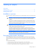
Where to go for additional help 1. Go to the HP website (http://www.hp.com). 2. Click Software & Driver Downloads from the left menu bar. 3. Type the product name in the For product box and press Enter. For example, type NC370T. 4. Download the drivers, firmware, or documentation as needed. HP contact information For the name of the nearest HP authorized reseller: • In the United States, see the HP US service locator webpage (http://www.hp.com/service_locator).
Introduction In this section Overview ................................................................................................................................................ 6 UTP CAT5 cable ...................................................................................................................................... 6 LED indicators ..........................................................................................................................................
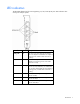
LED indicators The NC340T adapter has four auto-negotiating 10/100/1000 RJ-45 ports. LED indicators show activity/link and port speed. LED indicator Status Description Activity/Link On This mono-color green LED indicates that the link to the adapter is established. The adapter is receiving power and the cable connection is working. Off No link to the adapter is established. The adapter is not receiving power or the cable connection is faulty.
Installing an adapter In this section Installation overview ................................................................................................................................. 8 Preventing electrostatic discharge............................................................................................................... 8 Installing an adapter in a server.................................................................................................................
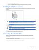
• Avoid touching pins, leads, or circuitry. • Always be properly grounded when touching a static-sensitive component or assembly. Installing an adapter in a server See the HP ProLiant server documentation for additional information on how to safely install a PCI card in the server. CAUTION: If the server is not PCI Hot Plug compliant, power it down and unplug the power cord from the power outlet before removing the server access panel. Failure to do so may damage the adapter or server. 1.
Specifications In this section HP NC340T PCI-X Quad-Port Gigabit Server Adapter specifications ............................................................ 10 UTP cable specifications.......................................................................................................................... 11 RJ-45 pinouts and crossover function ........................................................................................................
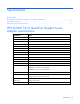
Specification Value Agency Approvals USA: FCC (CFR 47 part 15) and UL 60950 Canada: ICES-003 and CSA 60950 Japan: VCCI Korea: MIC (RRL), EMC Registration Australia: ACA, AS/NZS3548/EN55022:1998 (CISPR 22), EN55024:1998 European Union: EN 55022:1998 (CISPR 22), EN 55024:1998, and IEC 60950:1999 (EN 60950:2000) Safety Compliance UL Mark (US and Canada) CE Mark EN 60590 UTP cable specifications To connect to the network, the NC340T uses the following cable for 1000Base-T transmission: • CAT5 UTP or bet
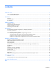
Pin Function Color match Function Pin 7 Brown 7 8 Brown/White 8 10/100 pinouts using external crossover through twisted-pair media When the crossover function is not provided within the hub or switch, you must implement the crossover through the twisted-pair media using the physical pinouts indicated.
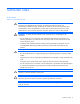
Gigabit over copper pinouts using internal crossover for RJ-45 Unlike connections in which the crossover function is implemented internally at the hub or switch, the NC340T provides its own automatic crossover function. This means you can wire twisted-pair media straight-through for adapter-to-hub, adapter-to-switch, or adapter-to-adapter connections using the pinouts indicated. NOTE: To operate at Gigabit speeds, all four pairs of wires must be terminated within the RJ45 connector.
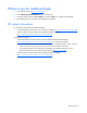
Gigabit over copper pinouts using external crossover through twisted pair media When a crossover function is not provided by the adapter, hub or switch, you must implement it through the twisted-pair media using the physical pinouts indicated.
Specifications 15
Regulatory compliance notices In this section Regulatory compliance identification numbers ........................................................................................... 16 Federal Communications Commission notice ............................................................................................. 16 Class A equipment ................................................................................................................................. 16 Class B equipment...................
residential area is likely to cause harmful interference, in which case the user will be required to correct the interference at personal expense. Class B equipment This equipment has been tested and found to comply with the limits for a Class B digital device, pursuant to Part 15 of the FCC Rules. These limits are designed to provide reasonable protection against harmful interference in a residential installation.
Cables Connections to this device must be made with shielded cables with metallic RFI/EMI connector hoods in order to maintain compliance with FCC Rules and Regulations. Canadian notice (Avis Canadien) Class A equipment This Class A digital apparatus meets all requirements of the Canadian Interference-Causing Equipment Regulations. Cet appareil numérique de la classe A respecte toutes les exigences du Règlement sur le matériel brouilleur du Canada.
Austria, Belgium, Cyprus, Czech Republic, Denmark, Estonia, Finland, France, Germany, Greece, Hungary, Iceland, Ireland, Italy, Latvia, Liechtenstein, Lithuania, Luxembourg, Malta, Netherlands, Norway, Poland, Portugal, Slovak Republic, Slovenia, Spain, Sweden, Switzerland, and United Kingdom. Notice for use in France and Italy Italy: Per l'uso del prodotto, è necessaria una concessione ministeriale.
Korean class A notice BSMI notice Disposal of waste equipment by users in private households in the European Union This symbol on the product or on its packaging indicates that this product must not be disposed of with your other household waste. Instead, it is your responsibility to dispose of your waste equipment by handing it over to a designated collection point for the recycling of waste electrical and electronic equipment.
Electrostatic discharge In this section Overview .............................................................................................................................................. 21 Grounding methods to prevent electrostatic discharge ................................................................................ 21 Overview To prevent damaging the system, be aware of the precautions you need to follow when setting up the system or handling parts.
Acronyms and abbreviations ACPI Advanced Configuration and Power Interface APM advanced power management CSA Canadian Standards Association DMA direct memory access IEEE Institute of Electrical and Electronics Engineers MDI-X medium dependent interface-crossover PCI peripheral component interface PCI-X peripheral component interconnect extended UTP unshielded twisted pair Acronyms and abbreviations 22
Index C cable configuration 10 cable connectors 10 cable, Ethernet crossover 10 cables, networking 8 cautions 3 E electrostatic discharge 7, 20 F features 5 G grounding methods 20 I installation overview 7 installing adapters 8 N NIC LEDs 6 R regulatory compliance notices 15 RJ-45 connectors 10, 11, 12, 13 S specifications 9 U UTP CAT5 cable 10 Index 23