HP NC360T PCI Express Dual Port Gigabit Server Adapter User Guide Part Number 432551-00B June 2007 (Second Edition)
© Copyright 2006, 2007 Hewlett-Packard Development Company, L.P. The information contained herein is subject to change without notice. The only warranties for HP products and services are set forth in the express warranty statements accompanying such products and services. Nothing herein should be construed as constituting an additional warranty. HP shall not be liable for technical or editorial errors or omissions contained herein.
Contents Technician notes ........................................................................................................................... 4 Where to go for additional help.................................................................................................................. 5 HP contact information ..................................................................................................................... 5 Introduction ......................................................
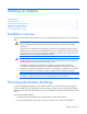
Technician notes In this section Where to go for additional help ................................................................................................................ 5 WARNING: Only authorized technicians trained by HP should attempt to repair this equipment. All troubleshooting and repair procedures are detailed to allow only subassembly/module-level repair.
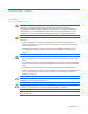
Where to go for additional help 1. Go to the HP website (http://www.hp.com). 2. Click Software & Driver Downloads from the left menu bar. 3. Type the product name in the For product box and press Enter. For example, type NC370T. 4. Download the drivers, firmware, or documentation as needed. HP contact information For the name of the nearest HP authorized reseller: • In the United States, see the HP US service locator webpage (http://www.hp.com/service_locator).
Introduction In this section Overview ................................................................................................................................................ 6 UTP CAT5 cable ...................................................................................................................................... 6 LED indicators ..........................................................................................................................................
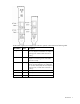
The NC360T Gigabit Server Adapter LED indicators operate as described in the following table. LED indicator Status Description Activity/Link On This mono-color green LED indicates that the link to the adapter is established. The adapter is receiving power and the cable connection is working. Off No link to the adapter is established. The adapter is not receiving power or the cable connection is faulty.
Installing an adapter In this section Installation overview ................................................................................................................................. 8 Preventing electrostatic discharge............................................................................................................... 8 Installing a low profile bracket ...................................................................................................................
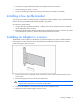
• Place parts on a grounded surface before removing them from their containers. • Avoid touching pins, leads, or circuitry. • Always be properly grounded when touching a static-sensitive component or assembly. Installing a low profile bracket You may have to install a low profile bracket to complete the product installation. The low profile bracket replaces the existing standard profile bracket shipped on the product. To install a low profile bracket: 1.
Connecting the network cable To secure the cable, plug the cable connector into the RJ-45 port. Ensure that the tab on the plug clicks into position indicating that it is properly seated. For more information, see UTP cable specifications (on page 12).
Specifications In this section HP NC360T PCI Express Dual Port Gigabit Server Adapter specifications..................................................... 11 UTP cable specifications.......................................................................................................................... 12 RJ-45 pinouts and crossover function ........................................................................................................
UTP cable specifications The NC360T adapter can use existing UTP CAT5 (or better) cable to deliver Gigabit Ethernet over copper, according to the IEEE 802.3ab specifications. For new installations, CAT5e (enhanced CAT5) cable is recommended. Maximum distances for Gigabit over copper cable are 100 meters (328 feet).
10/100 pinouts using external crossover through twisted-pair media When the crossover function is not provided within the hub or switch, you must implement the crossover through the twisted-pair media using the physical pinouts indicated.
Gigabit over copper pinouts using internal crossover for RJ-45 Unlike connections in which the crossover function is implemented internally at the hub or switch, the NC360T provides its own automatic crossover function. This means you can wire twisted-pair media straight-through for adapter-to-hub, adapter-to-switch, or adapter-to-adapter connections using the pinouts indicated. NOTE: To operate at Gigabit speeds, all four pairs of wires must be terminated within the RJ45 connector.
Gigabit over copper pinouts using external crossover through twisted pair media When a crossover function is not provided by the adapter, hub or switch, you must implement it through the twisted-pair media using the physical pinouts indicated.
Specifications 16
Regulatory compliance notices In this section Regulatory compliance identification numbers ........................................................................................... 17 Federal Communications Commission notice ............................................................................................. 17 Class A equipment ................................................................................................................................. 17 Class B equipment...................
residential area is likely to cause harmful interference, in which case the user will be required to correct the interference at personal expense. Class B equipment This equipment has been tested and found to comply with the limits for a Class B digital device, pursuant to Part 15 of the FCC Rules. These limits are designed to provide reasonable protection against harmful interference in a residential installation.
Canadian notice (Avis Canadien) Class A equipment This Class A digital apparatus meets all requirements of the Canadian Interference-Causing Equipment Regulations. Cet appareil numérique de la classe A respecte toutes les exigences du Règlement sur le matériel brouilleur du Canada. Class B equipment This Class B digital apparatus meets all requirements of the Canadian Interference-Causing Equipment Regulations.
Japanese notice Korean class A notice Korean class B notice BSMI notice Regulatory compliance notices 20
Disposal of waste equipment by users in private households in the European Union This symbol on the product or on its packaging indicates that this product must not be disposed of with your other household waste. Instead, it is your responsibility to dispose of your waste equipment by handing it over to a designated collection point for the recycling of waste electrical and electronic equipment.
Electrostatic discharge In this section Preventing electrostatic discharge............................................................................................................. 22 Grounding methods to prevent electrostatic discharge ................................................................................ 22 Preventing electrostatic discharge To prevent damaging the system, be aware of the precautions you need to follow when setting up the system or handling parts.
Acronyms and abbreviations ACPI Advanced Configuration and Power Interface APM advanced power management CSA Canadian Standards Association DMA direct memory access IEEE Institute of Electrical and Electronics Engineers LED light-emitting diode MDI medium dependent interface MDI-X medium dependent interface-crossover NIC network interface controller PCI Express Peripheral Component Interconnect Express PXE Preboot Execution Environment RoHS Restriction of Hazardous Substances Acronyms and abbrev
UTP unshielded twisted pair VDC voltage direct-current WOL Wake-on LAN Acronyms and abbreviations 24
Index C cable configuration 11 cable connectors 11 cable, Ethernet crossover 11 cables, networking 9 cautions 3 E electrostatic discharge 7, 21 F features 5 G grounding methods 21 I installation overview 7 installing adapters 8 N NIC LEDs 5 R regulatory compliance notices 16 RJ-45 connectors 11, 12, 13, 14 S specifications 10 U UTP CAT5 cable 11 Index 25