HP NC7771 PCI-X Gigabit Server Adapter User Guide June 2007 (Fourth Edition) Part Number 252458-00D
© 2003, 2007 Hewlett-Packard Development Company, L.P. Broadcom® is a registered trademark of Broadcom Corporation and/or its subsidiaries. Hewlett-Packard Development Company, L.P. shall not be liable for technical or editorial errors or omissions contained herein. The information in this document is provided “as is” without warranty of any kind and is subject to change without notice. The warranties for HP products are set forth in the express limited warranty statements accompanying such products.
Contents About This Guide Technician Notes...........................................................................................................................................v Where to Go for Additional Help.................................................................................................................vi Telephone Numbers ...............................................................................................................................
Contents Appendix C Specifications NC7771 PCI-X Gigabit Server Adapter Specifications............................................................................ C-1 UTP Cable Specifications ......................................................................................................................... C-2 Using UTP Category 5 Cable in Gigabit over Copper Installations................................................... C-2 RJ-45 Pinouts and Crossover Function.......................................
About This Guide Use this guide for reference when installing HP NC7771 PCI-X Gigabit Server Adapters. WARNING: To reduce the risk of personal injury from electric shock and hazardous energy levels, only authorized service technicians should attempt to repair this equipment. Improper repairs can create conditions that are hazardous. Technician Notes WARNING: Only authorized technicians trained by HP should attempt to repair this equipment.
About This Guide Where to Go for Additional Help HP updates networking software frequently to include new functionality and features. Complete the following steps to get the latest drivers, firmware, and documentation. 1. Go to the HP website (http://www.hp.com). 2. Click Support and Troubleshooting Information from the left menu bar. 3. Type the product name in the for product box and press Enter. For example, type NC370T. 4. Download the drivers, firmware, or documentation as needed.
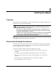
1 Introduction Overview The HP NC7771 PCI-X Gigabit Server Adapter is a high-performance, single port, Ethernet adapter that delivers up to 1000 Mb/s Ethernet over twisted-pair (copper) cabling. The NC7771 adapter has a fully integrated controller capable of auto-negotiating a link at 10, 100, or 1000 Mb/s. The network connection is made through an RJ-45 connector. LED indicators show the speed and activity of the link once it has been established.
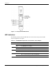
Introduction Figure 1-1: RJ-45 port and LED locations LED Indicators The following table describes the LED indicators located on the front panel of the HP NC7771 Gigabit Server Adapter. Table 1-1: 10/100/1000 LED Operations for the NC7771 Server Adapter LED Display Description 1000 On Link to the network is established at 1000 Mb/s. Off No 1000 Mb/s link is available. On Link to the network is established at 100 Mb/s. Off No 100 Mb/s link is available..
Introduction Unshielded Twisted Pair Category 5 Cable The NC7771 Gigabit Server Adapter can use existing Category 5 Unshielded Twisted Pair (UTP) (or better) cable to deliver Gigabit Ethernet over copper, according to the IEEE 802.3ab specifications. For new installations, Category 5e cable is recommended. For troubleshooting and other information about cabling, refer to “UTP Cable Specifications” in Appendix C.
2 Installing the Adapter Overview This chapter describes installation precautions and explains how to install the adapter. It also describes how to connect the network cable. WARNING: To avoid the risk of personal injury or damage to the equipment, consult the safety information and user documentation provided with the equipment before attempting installation of the adapter. Many servers are capable of producing energy levels that are considered hazardous.
Installing the Adapter Installing the Adapter in a Server Refer to the HP ProLiant server documentation for additional information on how to safely install a PCI card in the server. Figure 2-1: Installing the adapter in a server CAUTION: If the server is not PCI Hot Plug compliant, power it down and unplug the power cord from the power outlet before removing the server cover. Failure to do so may damage the adapter or server. 1. Remove the server cover and cover bracket from a PCI slot.
A Regulatory Compliance Notices Federal Communications Commissions Notice This equipment has been tested and found to comply with the limits for a Class B digital device, pursuant to Part 15 of the FCC Rules. These limits are designed to provide reasonable protection against harmful interference in a residential installation.
Regulatory Compliance Notices For questions regarding your product, contact: Hewlett-Packard Company P. O. Box 692000, Mail Stop 530113 Houston, Texas 77269-2000 Or, call 1-800- 652-6672 For continuous quality improvement, calls may be recorded or monitored. For questions regarding this FCC declaration, contact: Hewlett-Packard Company P. O.
Regulatory Compliance Notices European Union Notice Products bearing the CE marking comply with the EMC Directive (89/336/EEC) and the Low Voltage Directive (73/23/EEC) issued by the Commission of the European Community.
B Electrostatic Discharge Overview To prevent damage to the system, be aware of the precautions you need to follow when setting up the system or handling parts. A discharge of static electricity from a finger or other conductor may damage system boards or other static-sensitive devices. This type of damage may reduce the life expectancy of the device. To prevent electrostatic damage, observe the following precautions: • Avoid hand contact by transporting and storing products in static-safe containers.
C Specifications NC7771 PCI-X Gigabit Server Adapter Specifications Table C-1: NC7771 PCI-X Gigabit Server Adapter Specifications Specification Description Network Controller Chipset Broadcom® 5703CKHB Bus Type PCI-X or PCI Bus Width 32 or 64 bits Bus Speed 33, 66, 100, or 133 MHz Data Transfer Method Bus Master DMA Power Requirement Operating Voltage: +5V +/- 5% Power Consumption: 5 Watts Maximum: 1.0 A @ 5V(DC) Standards Supported IEEE 802.1Q, 802.3ab, 802.3u, 802.3x, 802.3 Dimensions 6.
Specifications Table C-1: NC7771 PCI-X Gigabit Server Adapter Specifications continued Specification Description Emissions Classifications Class B Agency Approvals USA: FCC (CFR 47 part 15) and UL 60950 Canada: ICES-003 and CSA 60950 Japan: VCCI Korea: MIC (RRL), EMC Registration Australia: ACA, AS/NZS3548/EN55022:1998 (CISPR 22), EN55024:1998 European Union: EN 55022:1998 (CISPR 22), EN 55024:1998, and IEC 60950:1999 (EN 60950:2000) Safety Compliance UL Mark (USA and Canada) CE Mark EN 60
Specifications 10/100 Straight-Through Pinouts If the crossover function is implemented internally, the port is labeled MDI-X (Medium Dependent Interface-Crossover). When an MDI-X port is connected to an MDI port, the twisted pair media should be wired straight-through using the physical pinouts indicated in Table C-2.
Specifications 10/100 Crossover Pinouts When the crossover function is not provided within the hub or switch, you must implement the crossover through the twisted-pair media using the physical pinouts indicated in Table C-3.
Specifications Gigabit over Copper Internal Straight-Through Pinouts Unlike connections in which the crossover function is implemented internally at the hub or switch, the NC7771 Server Adapter provides its own automatic crossover function. This means you can wire twisted-pair media straight-through for adapter-to-hub, adapter-toswitch, or adapter-to-adapter connections using the pinouts shown in Table C-4.
Specifications Gigabit over Copper External Crossover Pinouts When a crossover function is not provided by the adapter, hub or switch, you must implement it through the twisted-pair media using the physical pinouts shown in Table C-5.