HP Netserver LP 1000r User Guide HP Part Number P1810-90010 Printed in December 2000
Notice The information contained in this document is subject to change without notice. Hewlett-Packard makes no warranty of any kind with regard to this material, including, but not limited to, the implied warranties of merchantability and fitness for a particular purpose. Hewlett-Packard shall not be liable for errors contained herein or for incidental or consequential damages in connection with the furnishing, performance, or use of this material.
Contents 1 Controls, Ports, and Indicators................................................................... 1 Introduction ................................................................................................... 1 Front Panel................................................................................................ 1 Rear View.................................................................................................. 4 Applying Power to the HP Netserver ..............................
Contents Removing DIMMs ........................................................................................ 32 5 Installing Additional Boards ..................................................................... 35 Introduction ................................................................................................. 35 Tested PCI Boards .................................................................................. 35 Tools Required ..........................................................
Contents Tools Required ........................................................................................ 73 Rack Configuration Tools......................................................................... 73 Safety Precautions .................................................................................. 74 Preparing the Rack...................................................................................... 75 HP Netserver Rack Mount Parts List...............................................
Contents Netserver Will Not Power On ..................................................................100 Problems after Netserver is Powered On ................................................101 Error Messages ..........................................................................................102 POST Error Messages............................................................................104 Power-On Self Test (POST) Error Codes................................................
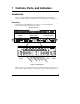
1 Controls, Ports, and Indicators Introduction Before operating the HP Netserver LP 1000r, familiarize yourself with the Netserver’s controls, ports, and indicators, as shown in Figures 1-1 through 1-3. Front Panel The front panel of the HP Netserver provides the controls and indicators commonly used when operating the Netserver.
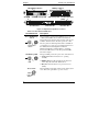
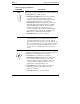
Chapter 1 Controls, Ports, and Indicators FDD Eject Button CD-ROM Eject Button RE S E T CD-ROM CD-ROM Activity LED SCSI Disk ID 0 FDD Activity LED Flexible Disk Drive (FDD) SCSI Disk ID 1 SCSI Disk ID 2 Figure 1-2. Input and Storage Device Controls Table 1-1. Power Switch and Indicators Control/Indicator Description Power On/Off/Sleep Switch This push-button switch turns the HP Netserver power On or Off, and if available, also transitions the Netserver between Power On and sleep states.
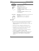
Chapter 1 Controls, Ports, and Indicators Table 1-2. Component Indicators LED ICON Description Temperature LED This Temperature LED has four distinctive states and is linked to the two processors and a sensor on the system board. • Steady Green for normal operation. • Alternating Green/Red indicates the temperature has crossed the warning threshold. If this condition continues a system crash and possible data corruption will occur. Must take action to correct problem.
Chapter 1 Controls, Ports, and Indicators LED ICON Disk ID 0, ID 1, and ID 2 LED Description These Disk LEDs have five distinctive states for the respective SCSI disk drive: • Off for SCSI drive not present • Steady Green for SCSI drive present • Steady Red for a SCSI drive failure • Alternating Green/Red at 1 Hz blink rate for a SCSI drive rebuild • Alternating Green/Red at 3 Hz blink rate for SCSI drive identification SCSI Activity This LED is the SCSI Hard Disk Drive Activity indicator and has two s
Chapter 1 Controls, Ports, and Indicators • The Video Port interface specifications are listed in Table A-4, "HP Netserver Hardware Specifications" and Table A-5, "Video Display Modes" of Appendix A, "Specifications." • The two LAN ports (LAN A/MGMT and LAN B) are for embedded controllers based on Intel’s 82559 10/100 BaseT Fast Ethernet controller. Only LAN A/MGMT is used with Alert-on-LAN 2 (AOL2) and Wake-onLAN remote management functions.
Chapter 1 Controls, Ports, and Indicators Applying Power to the HP Netserver Powering-Up the Netserver NOTE Turn on power to the monitor connected to the HP Netserver before you power-on the Netserver. This allows proper auto-configuration of video output of the Netserver as it boots up. 1. Ensure the HP Netserver’s power cord is connected to the power source. See Figure 1-3. 2. Press the Power push-button on the front control panel. See Figure 1-1.
Chapter 1 Controls, Ports, and Indicators Connecting AC Power to Multiple-Server Configurations The HP Netserver temporarily draws a large "inrush current" when first connected to an AC power source. This also occurs when the Netserver is in a standby mode (power is turned off, but the power cord is plugged into AC power). The inrush current is much greater than the Netserver’s normal operating current, and generally the AC power source can handle the normal inrush current.
Chapter 1 Controls, Ports, and Indicators The Netserver supports certain types of system activity, which is used as wake-up events from these sleep states. These wake-up events can be generated from the power button, LAN activity, and scheduled events. NOTE The HP Netserver’s power management policies (transitions between various power states) and the user options are specific to the particular ACPI-compliant NOS installed on the Netserver.
2 Opening and Closing the HP Netserver Introduction This chapter describes how to the remove the top cover, front bezel, and the air duct from the HP Netserver LP 1000r. WARNING Before removing the top cover, always disconnect the power cord and unplug telephone cables. Disconnect the power cord to avoid exposure to high energy levels that may cause burns when parts are short-circuited by metal objects, such as tools or jewelry.
Chapter 2 Opening and Closing the HP Netserver 4. Pull and lift the bezel out toward you and remove it from the chassis. See Figure 2-1. Pins Spring Latch (2) Figure 2-1. Front Bezel Location NOTE The front bezel pivots on two pins at the bottom and is held in place at the top with spring latches holding onto the top pins. The middle pins limit bezel rotation to an 80° angle. Replacing the Front Bezel 1. Place the bottom edge of the front bezel into the hinge pins at the bottom front of the chassis.
Chapter 2 Opening and Closing the HP Netserver Removing the Top Cover To remove the top cover, follow these steps: NOTE You do not need to removal the front bezel to remove the top cover of the Netserver. 1. If the HP Netserver is operating, log off all users and shutdown the operating system. Refer to the instructions in Chapter 1, "Controls, Ports, and Indicators." 2. Disconnect the power cord and any cables attached to the Netserver. 3.
Chapter 2 Opening and Closing the HP Netserver Figure 2-2. Removing the Top Cover Replacing the Top Cover To replace the top cover, follow these steps: 1. If the HP Netserver is already laying on a flat surface with no power applied, continue with Step 5. 2. If the HP Netserver was operating with the cover removed, power down the operating system and turn off the Netserver’s power switch. 3. Disconnect the power cord and any cables attached to the Netserver. 4.
Chapter 2 Opening and Closing the HP Netserver 7. Rotate the knob to the "Closed" position (counter clockwise position). See Figure 2-3. B A Figure 2-3. Replacing the Top Cover 8. Install the Netserver back into the rack and secure it to the rack. Refer to the instructions in Chapters 7, 8, or 13 (depending on the rack type) to install the chassis back into the rack. NOTE Some rack options do not require removing the HP Netserver from the rack to remove or replace the top cover.
Chapter 2 Opening and Closing the HP Netserver Removing the Air Duct The air duct directs air from the fan onto the heatsinks of both processors. The air duct also restricts access to both processors and all the DIMMs, and must be removed for full access. 1. Loosen the two captive screws holding the air duct to the system board. See Figure 2-4. 2. Remove the air duct from the system board. Figure 2-4.
3 Installing Mass Storage Devices Introduction The HP Netserver LP 1000r comes standard with an IDE CD-ROM and a flexible disk drive. The Netserver will accept up to three Hot Swap SCSI hard disk drives (HDD) in special mounting tray adapters. At least one Hot Swap SCSI hard disk drive is required for booting the Netserver. An optional SCSI tape backup drive may be connected to the external SCSI connector at the rear.
Chapter 3 Installing Mass Storage Devices • IDE Devices ◊ The embedded IDE controller is an Enhanced-IDE dual channel controller and provides two connectors (IDE-1 and IDE-2) for IDE devices. Refer to Figure A-1,"System Board Layout," in Appendix A, "Specifications." ◊ The IDE CD-ROM has only one connector on the cable from the primary channel (IDE-1) connector. ◊ A secondary IDE connector (IDE-2) is available, but is not used. • SCSI Device Selection ◊ Use only HP LVD low profile (1 inch) SCSI 3.
Chapter 3 Installing Mass Storage Devices • SCSI Drive Addressing ◊ The addresses of the SCSI drives are automatically assigned by the drive bay location in the chassis. Refer to Figure 3-1. No SCSI ID software settings or jumpers are required if using a HP NetRAID Controller board inserted into the only PCI slot. • SCSI Device Installation Order The three Hot Swap bays support various SCSI HDD configurations.
Chapter 3 Installing Mass Storage Devices Boot Priority The Netserver’s boot order should be considered when selecting a boot device. This is especially important if you are installing a board that requires an early number in the boot order. The board’s boot priority is set by its location in the boot order. By default the Netserver searches for boot devices in this order: 1. IDE CD-ROM drive 2. Flexible disk drive 3. Embedded SCSI A channel (Hot Swap SCSI Drives) 4.
Chapter 3 Installing Mass Storage Devices CAUTION To prevent damage to the Hot Swap SCSI hard disk drives, don’t use a HVD (high voltage differential) DAC controller. If the hardware mirroring option is required (which uses the SCSI channel of the HP NetRAID Controller board), refer to " Optional SCSI Drive Controller" later in this chapter. The instructions describe how to move the SCSI cable from the system board to the SCSI connector on the HP NetRAID Controller board.
Chapter 3 Installing Mass Storage Devices Installing Hot Swap Hard Drives Use this section to install the SCSI hard drives in the Hot Swap drive bays. CAUTION Protect the drive from static electricity by leaving it in its anti-static bag until you are ready to install it. Before handling the drive, touch any unpainted metal surface to discharge static electricity. When you remove the drive from the antistatic bag, handle it only by the frame. Do not touch the electrical components.
Chapter 3 Installing Mass Storage Devices 2. Remove the SCSI drive from its protective packaging and open the ejector arms as shown in Figure 3-3. The SCSI drive should already be mounted in the Hot Swap mounting tray adapter. a. Place both thumbs in the center opening at the front of the SCSI drive. b. Pull outward on both ejector arms, which moves the locking tabs inward. See Figure 3-4. You should hear the each ejector arm click as you pull it outward. 3.
Chapter 3 Installing Mass Storage Devices 6. Verify the tab on each ejector arm engages the edge of the drive bay as you close it. See Figure 3-4. You should feel each ejector arm click into place when it closes completely. Closing both ejector arms engages the drive with the electrical connector at the rear of the Hot Swap drive bay and seats the drive. Closing Ejector Arm Drive Ejector Arms Locking tab pivots when ejector arm is opened or closed. Figure 3-4. Closing Drive Ejector Arms 7.
Chapter 3 Installing Mass Storage Devices Removing Hot Swap Hard Drives CAUTION You must remove the drive slowly and then wait for the drive heads to park before completely removing the drive. Ensure you follow these instructions carefully to prevent handling damage, such as head slaps or head actuator unlocking. 1. To unlock the drive and remove it: a. Place both thumbs into the opening at the center of the drive. b. Pull out on both ejector arms with both thumbs at the same time.
Chapter 3 Installing Mass Storage Devices Figure 3-5. Removing a Hot Swap Drive CAUTION To prevent overheating or excessive electromagnetic radiation, use the filler panels to fill the unused drive bays. If the filler panels are left out of empty drive bays while the Netserver is operating, thermal damage and/or excessive EMI could occur. Optional SCSI Drive Controller Typically, this option is only used when hardware mirroring the Hot Swap SCSI drives.
Chapter 3 Installing Mass Storage Devices 2. Disconnect the SCSI cable end connected to the SCSI A cable connection on the system board. See Figures 3-6 and 3-7. 3. Unfold the cable and connect it to the SCSI connector on the HP NetRAID Controller board before installing the board into the Netserver. SCSI Connector Leave SCSI cable connected here. SCSI Backplane Board Figure 3-6. SCSI Backplane Board SCSI Backplane Board Disconnect SCSI A end of Cable. Figure 3-7.
4 Installing Additional Memory Introduction The HP Netserver LP 1000r’s main memory is implemented using four memory slots on the system board and it supports up to 4 GB (1 GB x 4) of memory. The Netserver uses only 3.3V, 168-pin, 133 MHz, buffered, SDRAM DIMMs and ships with at least one 256 MB DIMM. The embedded video controller is provided with 4 MB standard video memory and cannot be upgraded. NOTE Use only PC 133 (133 MHz) SDRAM DIMMs acquired from Hewlett-Packard.
Chapter 4 Installing Additional Memory Memory Installation Guidelines • The HP Netserver LP 1000r only uses 133 MHz (PC133) buffered SDRAM DIMMs, which are electrically different from the EDO and PC100 SDRAM memory modules used in other HP Netserver models. • DIMMs sizes supported are 128 MB, 256 MB, 512 MB, or 1 GB in any combination. • Supported memory capacity ranges from 128 MB to 4 GB maximum (1 GB in each of the 4 DIMM slots). The minimum capacity is 128 MB (one DIMM).
Chapter 4 NOTE Installing Additional Memory You do not need to remove the system board from the Netserver chassis to install or replace DIMMs. 5. Locate the DIMM slots on the system board. See Figures 4-1 and 4-2. 6. Loosen the two captive screws holding the air duct over the DIMM slots, and remove the air duct. See Figure 4-1. Figure 4-1.
Chapter 4 Installing Additional Memory 0 1 DIMM Slots 2 3 System Board (top view) Figure 4-2. DIMM Locations on System Board 7. Choose an empty slot on the system board to install a DIMM. DIMMs may be installed in any combination, in any slot, but HP recommends starting at slot 0 and filling the slots in order with the largest size first: DIMM slots 0, 1, 2, and 3. 8. Spread the two retaining latches on the slot outward. See Figure 4-3.
Chapter 4 Installing Additional Memory 9. Remove a DIMM from its container, handling the module by its edges. If not ready to install it, lay it on an anti-static surface until you are ready. CAUTION Use only HP PC133 (133 MHz) buffered SDRAM DIMMs. 10. Align the notches on the DIMM with the keys on the slot. See Figure 4-3. Retaining Latches (2) Keys DIMM Slot Notches Figure 4-3. DIMM to Slot Alignment WARNING Ensure you hold the DIMM tightly as you push it into the slot.
Chapter 4 Installing Additional Memory 0 1 DIMM Slots 2 3 System Board Figure 4-4. DIMM Insertion 12. Repeat Steps 7-11 to install all of the DIMMs for your memory configuration. 13. If you have completed the DIMM installation, close the Netserver and return it to the rack where power can be applied. Removing DIMMs You may need to remove a DIMM module to downsize your memory configuration or to replace a defective DIMM. 1. If the HP Netserver is already installed and working, power down the Netserver.
Chapter 4 Installing Additional Memory Refer to the appropriate chapter (Chapters 7, 8, or 13) for instructions. 4. Remove the top cover. Refer to Chapter 2, "Opening and Closing the HP Netserver." NOTE You do not need to remove the system board from the Netserver chassis to install or replace DIMMs. 5. Locate the DIMM slots on the system board. See Figures 4-1 and 4-2. 6. Loosen the two captive screws holding the air duct, which covers the DIMM slots, and remove the air duct. See Figure 4-1. 7.
5 Installing Additional Boards Introduction The HP Netserver LP 1000r provides one 64-bit PCI slot connected to a riser board on the system board, which will handle a full-length 32-bit or 64-bit PCI accessory board.
Chapter 5 Installing Additional Boards Accessory Board Installation Guidelines The following sections provide the guidelines necessary to install a PCI accessory board into the HP Netserver LP 1000r. IRQ Settings The IRQ settings are automatically assigned and don’t require user intervention. The HP Netserver uses the Plug-and-Play feature of the PCI board to correctly assign its resources automatically.
Chapter 5 Installing Additional Boards Remote Control Card The HP Netserver LP 1000r supports the HP Remote Control (PCI) card, which makes use of the HP TopTools remote management software. The Remote Control card requires an I2C connection to the system board, which is provided by the I2C connector on the daughter board (Integrated Remote Assistant circuitry) installed onto the system board. See Figures 5-1 and 5-2. Integrated Remote Assistant Board (daughter board) 2 IC Connector Figure 5-1.
Chapter 5 Installing Additional Boards WARNING The power supply will continue to provide standby current to the Netserver until the power cable is disconnected. 3. Remove the Netserver from the rack. Refer to Chapters 7, 8 or 13 (depending on rack type) to remove the Netserver from the rack. If there is enough space above the Netserver in the rack, you may be able to install the accessory board from the rear of the Netserver while it is still in the rack. 4.
Chapter 5 Installing Additional Boards 64-Bit PCI Slot (1) Riser Board (not shown) 2 IC Connector System Board (top view) Figure 5-2. PCI Accessory Board Slot NOTE Refer to "System Board Layout" in the Appendix A, "Specifications," for connections not shown in Figure 5-2. 7. Lift and rotate the securing clamp up to about a 45° angle. See Figure 5-3. The securing clamp holds the riser board in place and helps secure the PCI board. 8.
Chapter 5 Installing Additional Boards Securing Clamp Riser Board Figure 5-3. Riser Board and Securing Clamp 9. Lift up the latch and move the slot cover to the left away from the tabs and out of the chassis as shown in Figure 5-4. The PCI slot cover is held in place by the latch and must be saved for use later. NOTE 40 Save the slot cover for use later if the PCI board is removed. The slot cover must be installed in the empty PCI slot to prevent EMI interference.
Chapter 5 Installing Additional Boards Latch Tab Rest Slot Cover Tabs (2) Riser Board Figure 5-4. Removing the Accessory Slot Cover 10. If necessary, remove the riser board from the PCI slot. You may leave the riser board in place with smaller PCI boards, but you will need to remove the riser board from the PCI slot for larger PCI boards. 11. Slide the accessory board into the PCI slot on the riser board as shown in Figure 5-5.
Chapter 5 Installing Additional Boards Riser Board Installed Latch PCI Slot Figure 5-5. Inserting PCI Board-Riser Board 12. Insert the PCI board and riser board into the PCI connector on the system board. See Figure 5-5. 13. Secure the PCI board into the slot opening between the two tabs and close the latch. See Figures 5-4 and 5-5. 14. If you have a longer PCI board, you must use the board clamp to install the board into the Netserver. See Figure 5-6. a.
Chapter 5 Installing Additional Boards 16. Once the Netserver is returned to normal operation, you may need to install software drivers. The drivers for the new PCI board are either part of your existing system software or included on a flexible diskette or CD-ROM provided with the accessory board. Step C Lower Board Latch Step B Insert between tabs Step D Close Clamp Step A Open Clamp Board Clamp Tab Rest Figure 5-6.
6 Installing an Additional Processor Introduction The HP Netserver LP 1000r ships with at least one processor on the system board (primary processor socket – CPU 1) and the voltage regulator modules (VRMs) are embedded in the system board. Both processor sockets (primary and secondary) are located on the system board.
Chapter 6 Installing an Additional Processor • The processors must operate at the designated speed stated by the product type on the processor. • Use only processor upgrade kits with the same HP product number. This ensures the processor type, clock speed, and cache size are the same. • Ensure a processor is installed in the primary processor (CPU 1) socket before installing a processor in the secondary socket (CPU 2).
Chapter 6 Installing an Additional Processor Installing a Second Processor This section provides the instructions for installing a second processor and its accompanying heatsink on the system board. CAUTION The processor is sensitive to static electricity and can be easily damaged by improper handling. Do the following when handling the accessory kit: • Leave the processor in the anti-static bag until you are ready to install it.
Chapter 6 Installing an Additional Processor Refer to Chapter 2, "Opening and Closing the HP Netserver," to gain access to the system board. NOTE It is not necessary to remove the system board from the Netserver to install the second processor (CPU 2). 6. Loosen the two captive screws holding the air duct over the DIMM slots and remove the air duct. See Figure 6-2. Figure 6-2. Removing the Air duct 7.
Chapter 6 Installing an Additional Processor CAUTION Always wear a wrist-strap and use a static-dissipating work surface connected to the chassis when handling components. Ensure the metal of the wrist strap contacts your skin. 8. Open the ZIF (Zero Insertion Force) lever to allow removal of the terminator installed in the processor socket. See Figure 6-3. You need to pull the lever out away from the ZIF socket and then raise it to a full 90° to the system board.
Chapter 6 Installing an Additional Processor 10. Align the second processor over the empty processor socket. The socket has a triangle marking for pin-1 that should match the triangle for pin-1 on the processor near the end of the ZIF lever. See Figure 6-4. CAUTION Ensure you the align pin-1 of the processor with pin-1 of the processor socket or pin damage will occur. 11. Insert the second processor into the socket and close the ZIF lever to fully seat the processor.
Chapter 6 Installing an Additional Processor NOTE No speed switch settings are required for the supported processors (866, 933 MHz, or 1 GHz) in the HP Netserver. These processors rely on the internal settings within the processors and do not rely on external switch settings on the system board. Installing the Heatsink Once the processor is installed, the heatsink must be installed on top of the processor.
Chapter 6 Installing an Additional Processor NOTE The heatsinks are not reusable unless the thermal patch has been replaced each time the heatsink is removed, even if the heatsink is just temporarily removed from a processor and then re-installed on the same processor. Each time the heatsink is moved (slide) on the processor, some of the thermal material is removed from the thermal patch, which could cause poor heat transfer and overheating. 3.
Chapter 6 Installing an Additional Processor Hook Latch (hidden) Thumb Latch Step A Tab Tab Processor Socket Figure 6-5. Placing the Heatsink on the Processor CAUTION Ensure the left ridge on the bottom of the heatsink fits into the groove between the processor socket and processor, while both ridges should straddle the processor. If good contact is not made between the processor and the heatsink, the processor will overheat and possible damage may occur. See Figures 6-5 and 6-6. b.
Chapter 6 Installing an Additional Processor Hold Down Hook Latch Thumb Latch Step C Step B Ridges Figure 6-6. Setting the Latches CAUTION Failure to re-install the air duct will cause the Netserver to shut down with no messages displayed and possible damage to the processor. 5. Replace the air duct on the system board and tighten the captive screws. See Figure 6-7.
Chapter 6 Installing an Additional Processor Figure 6-7. Replacing the Air Duct Firmware and Software Changes This section describes the firmware changes provided by the HP Netserver Navigator CD-ROM and the possible need to reinstall the NOS to recognize the second processor. Upgrading the Firmware If your processor included a new HP Netserver Navigator CD-ROM, insert the CD into the HP Netserver LP 1000r CD-ROM drive and power on the Netserver.
Chapter 6 Installing an Additional Processor Reinstalling the NOS You may have to reconfigure or reinstall your NOS in order to use the additional processor. If you have gone from a uni-processor to dual-processor configuration, check your NOS documentation, or the Readme file and Configuration Advisor utilities on the HP Netserver Navigator CD-ROM. Removing a Processor and Heatsink Use this procedure to remove a processor and its heatsink. The heatsink must be removed before removing the processor.
Chapter 6 Installing an Additional Processor 8. If you intend to use the heatsink again for a new or replacement processor, you must insert a new thermal patch on the bottom of the heatsink. Refer to the heatsink installation procedure earlier in this chapter. CAUTION To prevent damage to the replacement processor, remove the old patch and install a new thermal patch to the bottom of the heatsink before installing it on the new processor.
7 Rack Mounting the HP Netserver (2-Post) Introduction This chapter provides the instructions for mounting the HP Netserver in a two-post (column) non-HP rack. The illustration below shows the characteristics of the 2-post (CPI – Chatsworth Products Inc.) rack. If you have one of the four-post HP racks, see Chapter 8, "Rack Mounting the HP Netserver (4-post)," or Chapter 13, "Alternative Rack Mounting (4-post)," for instructions.
Chapter 7 NOTE Rack Mounting the HP Netserver (2-Post) If you want to mount your Netserver in a third-party rack not mentioned in this guide, you may find relevant documentation on HP’s web site at the following URL: http://www.hp.com/netserver/support Before mounting the Netserver, determine the Netserver’s location in the rack relative to other rack components. The HP Netserver LP 1000r rack mounting kit only requires one EIA unit of space in the rack.
Chapter 7 Rack Mounting the HP Netserver (2-Post) Rack Configuration Tools HP rack configuration tools, including white papers, are available on the worldwide web. Enter the following URL in your browser: http://www.hp.com/netserver At the Web site, search for "configuration tools" and "high density rack solutions," specifically Rack Assistant, Rack Configuration, Order Assistant, and HP Netserver High Density Rack Solutions Overview (LP 1000r and LP 2000r).
Chapter 7 Rack Mounting the HP Netserver (2-Post) • Circuit Overloading - Ensure the total configuration of equipment in the rack does not overload the supply circuit. To this end, check the nameplate ratings on all equipment. Consider the effect of circuit overloading on overcurrent protection and supply wiring. • Reliable Earth Grounding - Maintain reliable earth grounding of rack-mounted equipment.
Chapter 7 Rack Mounting the HP Netserver (2-Post) NOTE Use the HP Rack Configuration Tools to determine where in the rack to mount the HP Netserver. The tools are available at: http: //www.hp.com/netserver/support 1. Use the mounting brackets to help find the Netserver location on the columns, as shown in Figure 7-2. The screw holes cover a span of only one EIA unit, which is the height requirement of the HP Netserver. 2.
Chapter 7 Rack Mounting the HP Netserver (2-Post) Preparing the HP Netserver Each HP Netserver has two inner-rails attached at the factory and shipped to customers. These two inner-rails must be removed to attach the brackets before the Netserver can be mounted in the rack. 1. Lay the HP Netserver on a flat surface. 2. Remove the front bezel on the Netserver chassis, if not already removed. See Figure 7-3. Optional (2) Figure 7-3. Removing Existing Hardware 3.
Chapter 7 Rack Mounting the HP Netserver (2-Post) original front mounting brackets to provide a connection for the front bezel. See Figure 7-3. 6. Mount the two flush mount brackets on the Netserver chassis using the four screws provided for each one. See Figure 7-4. Figure 7-4. Mounting Flush Mount Brackets 7. If required, mount the center mount brackets on the Netserver chassis using the four screws provided for each one. See Figure 7-5.
Chapter 7 Rack Mounting the HP Netserver (2-Post) Figure 7-5. Mounting Center Mount Brackets Placing the HP Netserver in the Rack Use this procedure to position the HP Netserver into the rack and secure it in place. Once the Netserver is in the rack, you can connect the front bezel to the Netserver chassis. WARNING To prevent personal injury or damage to the equipment, use two people to mount the HP Netserver into the rack. 1.
Chapter 7 Rack Mounting the HP Netserver (2-Post) Figure 7-6. Flush Mounting in the Rack 3. Position the Netserver’s two flush mount brackets over the holes (1st & 3rd) on the face of the two columns. See Figure 7-6. The masking tape or marking pen (marker) should provide the location of the holes on the two columns. See Figure 7-2. 4. Insert one screw through each bracket into the column, preferably the top or 1st hole on the column below the marker. 5.
Chapter 7 Rack Mounting the HP Netserver (2-Post) Figure 7-7. Center Mounting in the Rack Attaching the Front Bezel The front bezel attaches to the HP Netserver by pivoting on two pins at the bottom and holding onto the top pins with spring latches. The middle pins force the bezel to rotate in or out, ensuring a rotating action. 1. Position the Bezel in front of the HP Netserver LP 1000r as shown in Figure 7-8. 2. Push in on the bottom to engage the pins, allowing it to rotate up. 3.
Chapter 7 Rack Mounting the HP Netserver (2-Post) Pins Spring Latches (2) Figure 7-8. Installing the Bezel Continuing with the Rack Installation Process After you install the HP Netserver in the rack, refer to the white paper located on the HP web site for high-density rack configurations to continue with the process of installing and configuring the rack system. The white paper is titled HP Netserver High Density Rack Solutions Overview (LP 1000r and LP 2000r).
8 Rack Mounting the HP Netserver (4-Post) Introduction This chapter provides the instructions for mounting the HP Netserver in a 4-post (column) HP System/E or System/U rack. The illustration below shows the characteristics of the System/E and System/U racks. If you have the older HP Systems rack, see Chapter 13, "Alternative Rack Mounting (4-post)," for instructions.
Chapter 8 Rack Mounting the HP Netserver (4-Post) a b Characteristics of System/E and System/U Racks: c d a. 5-Cornered Columns b. Full Panel Vent c. "HP Rack System/E" or "HP Rack System/U" Name Plate d. Numbered EIA Units e. Anti-Tip Foot Extends Out Front or Back e Figure 8-1. HP System/E and System/U Rack Features NOTE If you want to put your Netserver into a third-party rack not mentioned in this guide, you may find relevant documentation on HP’s web site at the following URL: http://www.hp.
Chapter 8 Rack Mounting the HP Netserver (4-Post) NOTE If the HP Netserver is completely configured by the vendor before delivery to the customer, then mounting the HP Netserver in the rack may be the final step in the installation procedure. CAUTION If other rack components are to be mounted in the rack below the HP Netserver, install those components before starting to mount the Netserver.
Chapter 8 Rack Mounting the HP Netserver (4-Post) Safety Precautions Always keep the following safety and environmental issues in mind, especially if you install the HP Netserver in a non-HP rack environment: • Optimum Operating Environment - The optimum operating conditions for the HP Netserver is in an environmental controlled computer room with a temperature range of 20 to 22° C (68 to 72° F) at 40 to 60% relative humidity.
Chapter 8 Rack Mounting the HP Netserver (4-Post) Preparing the Rack The outer-rail assemblies must be released after shipment and the columns must be marked before mounting the outer-rail assemblies. Once the outer-rails are correctly mounted, then the HP Netserver LP 1000r can be installed into the rack. A template is not provided because the Netserver is exactly one EIA unit high and can only fit into one EIA unit, but not across two EIA units. NOTE The HP Netserver weighs 32 lbs. (14.5 kg.
Chapter 8 Rack Mounting the HP Netserver (4-Post) 3/4 CCW Release Spring Assembly 1/4 CW Figure 8-2. Releasing Spring Assembly Marking the Columns Use this section to mark the front and rear columns of the HP System/E or HP System/U rack. The outer-rails mount to the face of the front columns and the inside face of the rear columns. The masking tape (or marking pen) is used to identify and mark the locations on the columns.
Chapter 8 Rack Mounting the HP Netserver (4-Post) 2. Use the masking tape (or marking pen) to mark above the 3rd hole up on both front columns, as shown in Figure 8-3. Rear of Rack # "#" represents # the EIA unit numbers on the rack columns. # # 3rd Hole From Bottom # 1st Hole From Bottom # Masking Tape Marker Left Side Bottom of HP NetServer Mark this face of the columns with masking tape or marker pen. Right Side Front of Rack Figure 8-3. Location Marks on the Rack’s Columns 3.
Chapter 8 Rack Mounting the HP Netserver (4-Post) Anti-tip Foot Extended Leveler Screws (4) Figure 8-4. Mounting Outer-Rails to Columns 4. Match the outer-rail pins to the column holes (1st & 3rd) marked on the front and rear columns. See Figure 8-3. The mounting pins of the outer-rails should go into the inside face of the rear column and the front face of the front column. 5.
Chapter 8 Rack Mounting the HP Netserver (4-Post) 6. Repeat Steps 3 through 5 for the outer-rail on the right front and rear columns. 7. If you need to release the outer-rail assembly once it is installed into the rack, do the following: a. Place your finger inside the rail at the point shown by the arrow to release the spring tab. See Figure 8-5. b. Press in on the spring tab and pull the outer-rail assembly toward you at the front of the rack. See Figure 8-5.
Chapter 8 Rack Mounting the HP Netserver (4-Post) Placing the HP Netserver in the Rack Use this procedure to insert the HP Netserver into the outer-rail assemblies mounted in the rack. Once the Netserver is in the rack, then you can connect the cables to the rear of the Netserver. WARNING To prevent rack instability while mounting the HP Netserver, ensure the rack’s anti-tip foot is pulled forward out of the bottom of the rack. Failure to do so could result in injury and equipment damage.
Chapter 8 Rack Mounting the HP Netserver (4-Post) Figure 8-6. Mounting the HP Netserver 5. Slowly move the Netserver chassis into the outer-rail assemblies until the Netserver is completely in the rack. See Figures 8-6. The securing brackets on the front of the Netserver should stop the chassis from going all the way into the rack. 6. Secure the Netserver chassis to the rack with the captive screws.
Chapter 8 Rack Mounting the HP Netserver (4-Post) 1. Position the Bezel in front of the HP Netserver LP 1000r as shown in Figure 8-7. 2. Push in on the bottom to engage the pins, allowing it to rotate up. 3. Push the bezel in at the top to engage the spring latches. The spring latches should click when engaged. Pins Spring Latches (2) Figure 8-7.
9 Connecting the Monitor, Keyboard, Mouse, and UPS Introduction Use the procedures listed here to connect the peripheral devices to the HP Netserver LP 1000r. 1. Connect the monitor, keyboard, and mouse to the HP Netserver LP 1000r using the connections provided on the rear of the chassis. See Figure 9-1. When connecting the Netserver to peripherals, use the cable ties and labels provided with the product.
Chapter 9 Connecting the Monitor, Keyboard, Mouse, and UPS 2. Connect the power cord to the rear of the Netserver. See Figure 9-1. 3. If LAN cables are needed, you may connect them now or wait until you have verified the Netserver’s operation. Connecting the UPS (Uninterruptible Power Supply) 1. If you do not have an UPS (Uninterruptible Power Supply) located in the rack, install it before attempting to connect it to the Netserver. 2.
10 Configuring the HP Netserver Introduction This chapter describes how to configure the HP Netserver with the help of the HP Netserver Navigator CD-ROM, which is shipped with your Netserver. This CD-ROM also provides the latest information concerning your Netserver. As you configure the Netserver, it’s important to have the very latest configuration information. The CD-ROM will inform you of any applicable compatibility issues, and provide you with a current list of HP-tested peripherals and accessories.
Chapter 10 Configuring the HP Netserver Contents of the HP Netserver Navigator CD-ROM The Main Menu of the Navigator CD directs you to modules where you can perform the required configuration tasks, or access the utilities used in the configuration process.
Chapter 10 Configuring the HP Netserver Status Report Identification You must compare the Document Number on your HP Netserver Navigator CD-ROM with the most current Status Report’s Document Number for your HP Netserver model. • Each version of the HP Netserver Navigator CD-ROM has a four-digit Document Number, such as 77xx, corresponding to a Status Report, printed on the disk. • Each Status Report has a different Document Number. XX XX Document Number Figure 10-1.
Chapter 10 Configuring the HP Netserver 2. Click on CD Status Report to view the latest information or the CD Archive to view the release history. Netserver Navigator CD Status Report >> Ensures the latest documentation for your HP Netserver Netserver Navigator CD Archive >> HP Netserver Navigator CD Status reports are arranged with the most recent archived version first 3. Click on the Document ID number to view the latest Status Report (Release Notes).
Chapter 10 Configuring the HP Netserver under Embedded LAN Controllers in the LAN A submenu (Configuration > Embedded LAN Controllers > LAN A). You must also install the Netserver Agent software from the HP Netserver Navigator CD-ROM, and the AOL2 client software. Refer to the Netserver Alert-On-LAN 2 User Guide available online on the HP Netserver Online Documentation CD-ROM included with your system.
Chapter 10 Configuring the HP Netserver Menu Bar The Setup Utility provides a menu bar with several menu selections. The menu bar choices are: • User Preferences - Use this menu option to set the Netserver time, date and keyboard functions. • Security - Use this menu option to set Power-on password protections and hardware security options.
Chapter 10 Configuring the HP Netserver • Exit – Exit the Setup Utility by saving changes or exit without saving changes, which reverts to previous settings. When you exit, the HP Netserver reboots. Using the Setup Screens Online help explains the settings displayed on the Setup Utility screens. Instructions are also provided for navigating between the screens and entering or changing the setup data. • Press the right-arrow and left-arrow keys to move between selections on the menu bar.
Chapter 10 Configuring the HP Netserver 3. If necessary, use the up-arrow key to move to the System Time field. The "System Time" field is highlighted by default when the "User Preferences" menu is selected. This field actually consists of three sub-fields enclosed in brackets [xx:xx:xx]: hours to the left (24-hour clock), minutes in the middle, and seconds to the right. 4. Type in the hour and press Enter to move to the minutes field. 5.
Chapter 10 Configuring the HP Netserver 2. Use the right-arrow or left-arrow key to select Security from the menu bar. As soon as it is selected, the selections for the Security menu appear as shown below. ➢Power-On Password ➢Hardware Security The arrowhead ➢ indicates there is a submenu to select from. 3. If necessary, use the arrow key to move to the Power-On Password menu selection and press Enter. The Power-On Password is highlighted by default when the Security menu is selected.
Chapter 10 Configuring the HP Netserver The password is accepted and the next field just below it, "Re-enter new password: [ ]" or "Enter new password: [ ]" field is highlighted. For security reasons, the password does not appear on the screen. 6. Enter the new password in the "Enter new password: [ NOTE ]" field. Entering nothing in the "Enter new password" field followed by entering nothing in the "Re-enter new password" field will turn off the password setting, changing it to "Not Set." 7.
Chapter 10 Configuring the HP Netserver To access the Symbios SCSI Configuration Utility, refer to the following instructions. 1. Reboot the HP Netserver. If you are already in the boot process, you should see the following message appear. Press to start Symbios Configuration Utility... 2. Press keys to enter the utility. 3. Use the arrow keys to move the cursor, press Enter to select an option, and press Esc to exit. 4.
11 HP Netserver Online Documentation CD-ROM Overview The HP Netserver Online Documentation CD-ROM contains the entire set of documentation for your HP Netserver LP 1000r. The Online Documentation CD provides a web-based interface that allows you to quickly and efficiently locate necessary information including.
12 Troubleshooting Introduction If you are having problems installing your HP Netserver, there are a number of different tools available for troubleshooting, including the information provided in this chapter. • HP Netserver Online Documentation CD-ROM contains the following information in the HP Netserver LP 1000r Service Manual.
Chapter 12 Troubleshooting Common Installation Problems The following sections contain general procedures to help you locate installation problems. If you need assistance, HP recommends contacting your reseller first. If you need to get assistance from Hewlett-Packard, refer to the HP Netserver Warranty and Service/Support booklet provided with the Netserver. WARNING Before removing the cover, always disconnect the power cord and unplug telephone cables.
Chapter 12 Troubleshooting NOTE If the heatsink is not properly installed on the processor, the processor may overheat causing intermittent or unreliable operation leading to a possible system crash and permanent damage to the processor. 1. Remove the AC power cord, wait 15 seconds, reconnect the power cord, and try again. 2. Ensure all cables and the power cord are firmly plugged into the proper receptacles. 3.
Chapter 12 Troubleshooting 5. If the Netserver will not complete the boot process: a. Check the heatsinks on the processors for good contact. b. Consult the troubleshooting steps in the section "Hardware Problems" later in this chapter. c. If you get an error message or beep code, refer to the following section "Error Messages." d. Clear the CMOS memory and reboot. Refer to "Clearing the CMOS Configuration" later in this chapter. 6.
Chapter 12 Troubleshooting No Error Messages Displayed On Screen General Checks: 1. Listen for beep codes. If you hear a series of audible beeps refer to refer to the beep codes listed in the HP Netserver LP 1000r Service Manual. If no beep codes are heard, continue with the next step. 2. Verify all external cables and power cables are firmly plugged in. 3. Verify the power outlet is working. 4. Verify the Netserver and monitor are turned on. The power-on indicator should be illuminated. 5.
Chapter 12 Troubleshooting 5. Replace the cover and connect all cables. 6. Turn on the monitor and Netserver. 7. If the Netserver still does not work: ◊ Repeat steps 1, 2, and 3 of this section. ◊ Remove all accessories, except the primary boot hard disk drive. ◊ Replace the cover and connect all cables. ◊ Turn on the monitor and the Netserver. ◊ If the Netserver now works, replace the boards and accessories one at a time to determine which one is causing the problem. 8.
Chapter 12 Troubleshooting Table 12-1. POST Error Messages Message Corrective Action Operating system not found • Verify the desired boot drive has power and its SCSI cable connected. • Verify the SCSI cable is securely plugged into the SCSI connector on the system board. • Verify the boot device is enabled in the Setup Utility under the Security menu. • Verify the boot device has an operating system installed. Keyboard error (The LP 1000r will complete the boot process without a keyboard connected.
Chapter 12 Troubleshooting • Press to run Setup. System CMOS checksum bad • Change settings as required. • Choose the Exit option, selecting Save Changes and Exit to save the new settings. The Netserver should reboot. Power-On Self Test (POST) Error Codes These error codes (POST codes) appear in normal video if an error condition occurs during the boot process of the HP Netserver LP 1000r.
Chapter 12 Troubleshooting 7. Turn on power to the Netserver and the following message displays: Incorrect System Configuration 8. Press to run the Setup Utility when appears. 9. Make any configuration changes required. 10. Choose the Exit option and save the changes to save the configuration and exit the Setup Utility. Switch 1 Position Configuration Switch Spring Latch Battery Figure 12-1.
Chapter 12 Troubleshooting Resetting a Lost Password If you have forgotten the Power-on password, you can reset it using the configuration switch on the system board. NOTE If you have forgotten the Power-on password, your Netserver will function normally, but you will not be able to access the configuration settings in the Setup Utility or complete the boot process if you reboot the Netserver. 1. Turn off power to the HP Netserver. 2. Remove the cover. 3.
Chapter 12 Troubleshooting 1. If nothing is displayed on the screen, but the Netserver starts and you have verified the keyboard, disk drives, and other peripheral devices are functioning properly: ◊ Verify the monitor is plugged in and power is turned on. ◊ Verify the brightness and contrast controls of the monitor are properly set. ◊ Verify the monitor video cable is securely connected to the Netserver. ◊ Turn off the monitor and Netserver and unplug each one from the power outlet.
Chapter 12 Troubleshooting CD-ROM Drive Does Not Work 1. Verify a CD is inserted in the drive. 2. Verify the power and data cables are correctly connected to the device. 3. Verify the CD-ROM is configured correctly in the menu located under the Security menu in the Setup Utility. 4. If you intend to boot from the CD, ensure the option is enabled in the Setup Utility. 5. For further information, refer to your CD-ROM documentation.
Chapter 12 Troubleshooting Refer to Chapter 2, "Opening and Closing the HP Netserver," to gain access to the system board. 3. If necessary, remove the PCI board to gain access to the battery. See Figure 12-2. 4. Insert a small flat-blade screwdriver or similar tool between the battery and spring latch. See Figure 12-3. 5. Push the spring latch away from battery to release the battery. The spring contacts beneath the battery cause it to pop up allowing you to grasp the battery. 6.
Chapter 12 Troubleshooting 9. Ensure the spring latch holds the battery firmly. 10. If necessary, replace the PCI board and replace the top cover. 11. Re-install the Netserver into the rack. 12. Power on the Netserver and reset the CMOS settings. Problems Running the Setup Utility If you cannot run the Setup Utility, the HP Netserver’s configuration in CMOS memory may have become corrupt. The only way to recover from a corrupted configuration is to clear it.
13 Alternative Rack Mounting (4-Post) Introduction This chapter provides the instructions for mounting the HP Netserver in a four-post (column) HP Systems rack. Figure 13-1 shows the Systems rack. If you have the newer 4-post HP System/E or System/U racks, go to Chapter 8. If you are mounting the Netserver in a 2-post non-HP rack, refer to Chapter 7, or see the documentation in the appropriate rack accessory kit. a b c Characteristics of HP System Rack: d a. b. c. d. e.
Chapter 13 Alternative Rack Mounting (4–Post) Before mounting the Netserver, determine the Netserver’s location in the rack relative to other rack components. Proper placement is vital both for safety and operating efficiency. For more information, refer to "Rack Configuration Tools" later in this chapter. NOTE If the HP Netserver is completely configured by the vendor before delivery to the customer, then mounting the HP Netserver in the rack may be the final step in the installation procedure.
Chapter 13 Alternative Rack Mounting (4–Post) Safety Precautions Always keep the following safety and environmental issues in mind, especially if you install the HP Netserver in a non-HP rack environment: • Optimum Operating Environment – The optimum operating conditions for the HP Netserver is in an environmental controlled computer room with a temperature range of 20 to 22° C (68 to 72° F) at 40 to 60% relative humidity.
Chapter 13 Alternative Rack Mounting (4–Post) Preparing the Rack The outer-rail assemblies must be released after shipment and the columns must be marked before mounting the outer-rail assemblies. Once the outer-rails are correctly mounted, then the HP Netserver LP 1000r can be installed into the rack. A template is not provided because the Netserver is exactly one EIA unit high and can only fit into one EIA unit, but not across two EIA units. NOTE The HP Netserver weighs 32 lbs. (14.5 kg.) fully loaded.
Chapter 13 Alternative Rack Mounting (4–Post) 3/4 CCW Release Spring Assembly 1/4 CW Figure 13-2. Releasing Spring Assembly Marking the Columns Use this section to mark the front and rear columns of the HP Systems rack. The outer-rails mount to the face of the front columns and the inside face of the rear columns. The masking tape (or marking pen) is used to identify and mark the locations on the columns.
Chapter 13 Alternative Rack Mounting (4–Post) Rear of Rack represents the EIA unit numbers on the rack columns. Masking Tape Marker Left Side Mark this face of the columns with masking tape or marker pen. Right Side 3rd Hole From Bottom 1st Hole From Bottom Bottom of HP NetServer Front of Rack Figure 13-3. Location Marks on the Rack’s Columns 3. Mark the inside face of the left-rear and right-rear rack columns, with masking tape, as shown in Figure 13-3.
Chapter 13 Alternative Rack Mounting (4–Post) Anti-tip Foot Extended Leveler Screws (4) Figure 13-4. Mounting Outer-Rails to Columns 5. With the outer-rails held in position at the rear, push in on the front outer-rail mount. A tension spring allows the outer-rails to compress during installation. The outer-rails are held in place at of the front of the rack by a flat spring tab at the rear face of the front columns. See Figures 13-2 and 13-5. 6.
Chapter 13 Alternative Rack Mounting (4–Post) Spring Tab View Rotated 90 Degrees CCW Figure 13-5. Releasing the Outer-Rail Assembly Placing the HP Netserver in the Rack Use this topic to insert the HP Netserver into the outer-rail assembly mounted in the rack. Once the Netserver is in the rack, you can connect the cables to the rear of the Netserver.
Chapter 13 Alternative Rack Mounting (4–Post) 1. Lower the leveler screws on the rack’s lower four corners to make firm contact with the floor. See Figure 13-4. 2. Ensure you have extended the anti-tip foot from the rack before continuing this procedure. See Figure 13-4. NOTE The HP Netserver weighs 32 lbs. (14.5 kg.) fully loaded. It is not necessary to use two people when placing the Netserver into the rack, but it may be helpful. 3. Lift the HP Netserver by its inner-rails off the floor or pallet. 4.
Chapter 13 Alternative Rack Mounting (4–Post) The securing brackets on the front of the Netserver should stop the chassis from going all the way into the rack. 6. Secure the Netserver chassis to the rack with captive screws. Attaching the Front Bezel The front bezel attaches to the HP Netserver by pivoting on two pins at the bottom and grasping the top pins with spring latches. The middle pins force the bezel to pivot in or out, ensuring a rotating action. 1.
A Specifications Introduction This appendix provides the power requirements, operating conditions (environmental requirements), physical requirements, hardware specifications, and video resolutions of the HP Netserver LP 1000r. The system board layout and the unused connectors are also provided. See Figures A-1 and A-2. Requirements The following tables provide the specifications required for normal operation of the HP Netserver LP 1000r. Table A-1.
Appendix A Specifications Table A-2.
Appendix A Specifications Table A-4. HP Netserver Hardware Specifications Processors Intel Pentium III (up to 2 processors) processors, at supported speeds of 866, 933 MHz and 1 GHz, with 256 KB level 2 cache on processor Chipset RCC LE chip set with 133 MHz bus speed support Memory Supports up to four SDRAM DIMMS for a maximum of 4 GB. Supported DIMM types: 128 MB, 256 MB, 512 MB and 1 GB unbuffered (registered), 72 bits wide, ECC single-bit correcting, multi-bit detecting.
Appendix A Specifications System Board Layout Battery Serial A/MGMT (B) Video (B) LAN A/ LAN B MGMT Parallel (T) UBS (2) Keyboard (B) Mouse (T) PCI Slot Processor 1 Config Switch IDE-2 Processor 2 Integrated Remote Assistant Board (Daughter Board) Power Connector 0 1 DIMM 2 Slots 3 FDD + Power SCSI B SCSI A IDE-1 (B) = Bottom, (T) = Top Figure A-1.
Appendix A Specifications Not used Wake-onLAN (WOL) Not used Power Supply Speed Monitor Wake-onRing (WOR) Not used Not used Processor (CPU) Fan Integrated RA Board Connectors (2) (Daughter Board) Not used PCI Board Fan Memory Fan Power, Reset Buttons, Power LED Management Function Not Used See Default Settings Figure A-2. System Board Connectors (Used/Unused) NOTE If the switch is loaded, refer to the following table (Table A-6, "Default Settings") for switch default settings. Table A-6.
Index A ACPI Advanced Configuration and Power Management Interface, 2, 7 Advanced Configuration and Power Management Interface ACPI, 7 air duct remove for processors, 48 air duct, 29 Air Duct removing, 14 Alert-On-LAN 2 Magic Packet, 88 Setup Utility, 89 Alert-on-LAN 2 (AOL 2) LAN A only, 90 anti-tip foot rack installation, 77, 118 B boot device order Setup Utility, 90 boot device priority boot order, 18 changing boot order, 94 boot order boot device priority, 18 CD-ROM, 18 CD-ROM, 36 default, 18 flexible d
Index DIMM sizes 1 GB, 28 128 MB, 28 256 MB, 28 512 MB, 28 DIMMs air duct removal, 29 installation, 27 installation guidelines, 28 non-compatible, 27 open slot configuration, 28 removing, 32 retaining latches, 33 slots 0 through 3, 28 supported memory capacity, 28 Disk Array Controller board HP NetRAID 1M, 36 HP NetRAID 1Si, 36 HP NetRAID 2M, 36 recommendation, 36 Diskette Library, 99 display modes, 125 Drive Array Controller (DAC), 18 drive types supported flexible disk drive, 15 IDE CD-ROM, 16 low-voltag
Index Hot Swap SCSI ID no jumper settings, 17 Hot Swap SCSI ID assigned by location, 17 no controller board jumper settings, 17 HP DiagTools Utility, 99 HP Management Solutions, 88 HP NetRAID 1M, 19 HP NetRAID 1Si, 19 HP NetRAID 2M, 19 HP Netserver rack installation, 114 tool-less rack installation, 114 HP Netserver controls, 1 front panel, 1 indicators, 1 inrush current, 7 ports, rear panel, 4 powering down, 6 powering up, 6 rack installation, 59, 71 rack mount kit, 62, 75, 116 required tools (rack instal
Index memory cache Setup Utility, 90 monitor troubleshooting, 108 video connection, 83 mouse, 83 mouse troubleshooting, 109 O Order Assistant, 27 outer-rail release compression spring, 75, 116 spring tab, 79, 119 P password resetting, 108 password problems, 108 PCI board PCI-to-PCI bridge, 38 PCI boards software drivers, 43 PCI slot riser board, 38 PCI slot devices, 90 PCI slots one 64-bit slot, 35 riser board, 35 ports Alert-on-LAN 2 (AOL2), 5 keyboard, 4 LAN, 5 mouse, 4 serial, 4 Wake-on-LAN, 5 ports ext
Index R rack configuration tools, 61, 73, 114 rack installation alternative, 113 anti-tip foot, 77, 118 rack mount kit parts list, 62, 75, 116 rear panel ports, 83 Remote Control card I2C connector, 37 Remote Control card RMC, 37 removing front bezel, 9 removing top cover, 11 replacing top cover, 12 retaining latches DIMMs, 31 S SCSI channels changing boot order, 94 SCSI configuration utility Symbios SCSI Configuration Utility, 94 SCSI configuration utility, 94 SCSI Configuration Utility change boot order,
Index EMI interference prevention, 40 spring tab outer-rail release, 79, 119 support ticket text file, 89.