DAT 72 Model 5242-2SE Rackmount Tape Unit User's Guide 4mm Tape Drives for HP Integrity NonStop NS-Series Carrier Grade Servers NonStop S-Series Central Office Servers 5242-2SE Tape Drives Part Number 528297-003 Release Version Updates (RVU) Support G06.10 and all subsequent G-series RVUs, H06.
i List of Acronyms ANSI BOT CPU ECC FRU LAN LCD LED MFC POST SCSI ii Terminology Used in This Manual Emulator Host Initiator Target iii American National Standard Institute Beginning of tape Central processing unit Error correction code Field replacement unit Local area network Liquid crystal display Light emitting diode Multifunction controller Power-on self-test Small Computer Systems Interface The fast SCSI bridge between the host and the tape drive that provides intelligence to execute commands to
v Table of Contents Chapter One – Introduction ................................................................................................................... 1 Product Description..................................................................................................................... 1 Product Parts List ........................................................................................................................ 1 Features .......................................................
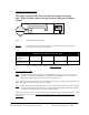
vi 5242-2SE Tape Path Cleaning The Media Caution LED is located on the front panel of the tape drive. When it flashes amber, the tape heads are dirty and should be cleaned. Tape Media Caution 1 2 1 2 Detail A Figure 1 5242-2SE Media Caution LED Warning The tape heads must be cleaned regularly. Use the recommended cleaning schedule as specified per cartridge type. See Table 1.
Chapter One – Introduction 1.1 Product Description The 5242-2SE was designed and built specifically for use in a telecommunications central office environment. Typical applications include file backup, archive, and software loading. The 5242-2SE contains two independent DAT drives. The 5242-2SE unit mounts in a 19-inch rack. Each module consists of two 4mm DAT72 drives. It has built-in power-on-self-test (POST) diagnostic.
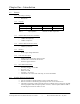
Chapter One – Introduction 1.3 Features 1.3.1 Recording technology: • 1.3.2 Helical scan Capacity: Cartridge Type 125m cartridge 170m cartridge Table 3 1.3.3 10MB/s synchronous SCSI-3, high-voltage differential Intelligent front end, backlit, supertwist LCD Advanced drive test and exercise function Firmware upgrade function Drive Rated Performance: • • • • • 1.4 3.0MB/s uncompressed 6.0MB/s compressed LCD and control panel: • • • 1.3.7 *Assumes 2:1 data compression Interface: • 1.3.
Chapter One – Introduction 1.5 SCSI Compatibility The interface for the 5242-2SE tape drive complies with the American National Standard Institute (ANSI) standard X3T9.2 (SCSI-2). This standard defines the specifications for the Small Computer System Interface (SCSI). As defined by the ANSI, SCSI is essentially an input/output bus for interconnecting computers and peripherals. 1.6 DAT72 Format and Compatibility The 5242-2SE's DAT72 format is an extension of the DDS-3 formats.
Chapter Two – Installation 2.1 Unpacking the 5242-2SE Carefully unpack the 5242-2SE and inspect for damage. If any damage is observed, immediately notify HP. Save the carton and packing materials in case your need to ship your unit. 2.2 Installing the 5242-2SE 2.2.1 Slide the 5242-2SE into the adapter bracket. Using the four 10-32 screws and washers (provided), secure the 5242-2SE to the adapter bracket. 2.2.
Chapter Two – Installation If the tape unit is… Then… the last of multiple devices on the SCSI bus or the only device on the bus – install the differential terminator plug into the unused SCSI connector on the rear panel. in a daisy-chained configuration with other SCSI devices and is not the last device on the bus – install the terminator on the last device on the bus. Table 4 Note: 2.
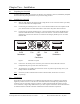
Chapter Two – Installation Enter Set-Up 1 PRESS to Select SCSI ID: [00] PRESS to Alter Tape ID: [00] *NOT sel ectable* Tape Term:On *NOT sel ectable* Density: [FF] *NOT sel ectable* Rwr% 0.5 Ecc: 0.5 PRESS to alter Exit Set-up 1 PRESS to Select Figure 4 2.5.3 Select the SCSI ID screen by pushing the mode switch when the SCSI ID screen appears. This configuration menu item allows you to set the SCSI ID. When the screen reads PRESS to Alter, push the mode switch.
Chapter Two – Installation 1. 2. 3. Note: Check that the drive is not engaged in any SCSI activity. Insert the firmware upgrade tape into the drive. The upgrade process automatically takes place. During the actual erasure and reprogramming of the firmware, it is critical that you do not power down the drive. The front panel LEDs flash rapidly during this critical time. After about three minutes, when the upgrade is complete, the cartridge ejects. Remove it, and put it in its box.
Chapter Three - Controls and Indicators 3.1 Controls and Indicators This chapter discusses the 5242-2SE controls and indicators by function, location, and type. Figure 6 identifies all the connectors and switches on the 5254-2SE front and rear panels. DRIVE B DRIVE A SCSI Connectors Figure 6 3.2 Fan DC Fan Power Input Connectors SCSI Connectors 5242-2SE front and rear panels Understanding the Tape Drive LEDs Each 5242-2SE tape drive has a pair of LEDs that indicate drive status. See Figure.
Chapter Three - Controls and Indicators 3.2.2 3.2.3 • Steady green means a tape is loaded. • Fast flashing green means read or write operations are occurring. The Media Caution LED (number 2 in Figure 7) is amber, indicating a fault condition: • Slow flashing amber indicates that the tape drive heads need to be cleaned or the tape cartridge is wearing out. • Steady amber indicates a hard fault. The unit should be replaced. Call the HP Global Customer Support Center.
Chapter Four - Tape Cartridges 4.1 Tape Cartridge A tape cartridge is a storage device that contains either magnetic tape or a cleaning ribbon inside a protective case. The cartridge protects the tape or ribbon and makes handling easier. The two types are cleaning cartridges and data cartridges. Cleaning cartridges or tapes are used to clean the recording heads of the tape drive with a cleaning ribbon. Data cartridges or data tapes hold magnetic storage media for the tape subsystem.
Chapter Four - Tape Cartridges 4.3 Write-Protecting a Data Cartridge Each data cartridge has a write-protect switch that protects the data cartridge from being overwritten. See Figure 9 to protect the cartridge. Slide the switch all the way to the left. The hole will be visible. Data can then be read from the tape but not written to it. Slide the switch to the right (covering the hole) to writeenable the cartridge. Data can then be written to and read from the tape.
Chapter Four - Tape Cartridges Figure 10 4.5.3 Loading a tape cartridge During the load sequence: Tape LED (number 1 in Figure 11) slowly flashes green while the tape is being loaded. The Tape LED becomes a steady green to indicate the tape is loaded. If an excessive number of errors is detected, the Media Caution LED (number 2 in Figure 11) flashes amber. Tape Media Caution 1 2 1 2 Detail A Figure 11 4.
Chapter Four - Tape Cartridges The Eject button is disabled and has no effect when pushed. It does not initiate an unload sequence. A LOAD/UNLOAD command with the LOAD bit set to zero takes the drive off-line and unthreads the tape but does not eject the cartridge. The effects of PREVENT MEDIA REMOVAL continue until an ALLOW MEDIA REMOVAL command is received or the drive is reset. 4.7 Forcing the Ejection of a Cartridge Caution: You might lose data if you force an eject.
Chapter Five - SCSI Bridge Electronics 5.1 Introduction to the 5242-2SE Display At the heart of the display system is the Infourmm SCSI bridge, which provides performance information about the tape operation. In addition to bridging communications between the host and tape drive, Infourmm autonomously sends commands to the tape drive to extract the data necessary for the display.
Chapter Five - SCSI Bridge Electronics 5.4 Display Unit LEDs The display unit has two LEDs, one green and one amber. The green LED indicates that data compression is active. The amber LED is a user-programmable, error-alert indicator that lights when the error-rate percentage reaches a predetermined value. This value can be set or altered using the mode switch in conjunction with the setup menus. 5.
Chapter Five - SCSI Bridge Electronics Figure 15 5.7 Identification of LCD items Performance LCD Format Upon receiving a TEST UNIT READY or INQUIRY SCSI command from the host, the LCD switches to the Performance format which is the main operational format of the LCD. The top two lines of the LCD always display the current SCSI command and the tape-capacity bar graph. The bottom two lines of the display alternate between five performance/status items. Figure 16 5.7.
Chapter Five - SCSI Bridge Electronics Total data bytes read from or written to the unit appear with a KB (1024), MB (1024 x 1024) or GB (1024 x 1024 x 1024) multiplier. On the first read or write command following a rewind, the count is set to zero. Write E F TOTL XFR 74MB Figure 18 5.7.
Chapter Five - SCSI Bridge Electronics The average compression/decompression ratio appears as the ratio of the compressed and uncompressed data lengths reported by the tape drive. The ratio always appears in the format X.X:X. 5.7.5 Remaining Capacity This value is an estimate of remaining tape capacity. It is computed by multiplying the average compression ratio by the remaining block count. KB, MB, and GB represent multipliers of 1024, 1024 x 1024, and 1024 x 1024 x 1024, respectively.
Chapter Five - SCSI Bridge Electronics When the desired tape density appears, push the mode switch to select it. The selected setting is used until the unit is power cycled or reset. These choices are offered: C0 = Compressed format 40 = Uncompressed format FF = Density controlled by the host software Note: 5.9 The setting from the last change of tape density is used as the default start-up value.
Chapter Five - SCSI Bridge Electronics 5.10.2 Changing a Setting Depending on the menu item, alter settings by using these methods. When the instruction reads PRESS to Alter, you have the option to exit the editing mode to review the settings. Numeric-Entry Method With this method you change settings by entering a decimal or hexadecimal number, digit-by-digit. The LCD shows the instruction PRESS to Incremnt the alterable digit. The highlighted digit is incremented by pressing the mode switch.
Chapter Five - SCSI Bridge Electronics 5.11 Setup 1 Configuration Display Format Items Enter Set-Up 1 PRESS to Select SCSI ID: [00] PRESS to Alter Tape ID: [00] *NOT sel ectable* Tape Term: On *NOT sel ectable* Density: [C0] PRESS to Alter Rwr% 0.5 Ecc: 0.5 PRESS to Alter Figure 28 5.11.
Chapter Five - SCSI Bridge Electronics This is factory-configured and is tnot selectable. Tape Term:On *NOT sel ectable* Figure 31 5.11.4 Tape termination Manually Selecting the Tape Density Tape density format can be controlled by the display unit or by the NonStop server. When the appropriate drivers exist, the latter method is generally preferred, and a setting of FF should be used. Other density values shown allow the SCSI bridge electronics to control the tape density.
Chapter Five - SCSI Bridge Electronics Note: Because the beginning of tape is written to every time a tape is unloaded, this area of the tape tends to wear sooner than the rest of the tape media's length. As a result, it is not unusual to experience rewrites or ECCs at the beginning of tape. If these situations occur, the predetermined thresholds can be exceeded early, but the percentage then drops below the threshold as reading or writing moves further down the tape.
Chapter Five - SCSI Bridge Electronics 5.12.2 Configuring the options setting If your configuration or host environment requires unique settings or special configurations, HP can provide assistance and firmware configurations for specific platforms, software, or drives through the use of this menu item. This setting is configured at 00001400 and should not be changed by the user.
Chapter Five - SCSI Bridge Electronics Pressing the mode switch at this menu item invokes the drive self-test and offers a series of options from which you can select. This standalone exerciser can be used to diagnose problems within the tape drive. Modes of operation include fixed/variable block transfers, spacing, differing densities/compression modes, and a means to control the running time. Records are written with interspersed filemarks, rewound, and read/verified.
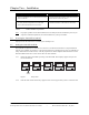
Chapter Five - SCSI Bridge Electronics Figure 40 Example drive test Enter Set-Up 3 PRESS to Select Drive Test PRESS to Run Custom Test PRESS to Select 1MB to Xfer PRESS to Increment Variable Mode PRESS to Toggle Run Once PRESS to Toggle Ready to Run PRESS to Start Ready to Run PRESS to Escape Ready to Run PRESS to Confirm Ready to Run Waiting for tape Write E F TOTL XFR 1024MB Write E F XFR RATE 301KB/s Write E F COMPRESS 1.0:1 Write E F RWr RATE 0.0% Write E F REMAIN'G 1.
Chapter Five - SCSI Bridge Electronics 5.13.2 Activating a hardware self-test Enter Set-Up 3 PRESS to Select Hdwr Test PRESS to Run Hdwr Test Testing Scsi Hdwr Test Ram Test & Reset InFourmm ======== Power On SelfTest C7438A Rev L610 5242 T133BID5 Figure 42 Activating a hardware self-test This diagnostic item provides you with a more thorough method of testing memory and peripheral hardware. 5.13.
Chapter Five - SCSI Bridge Electronics 5.13.4 Loading a Code Tape Enter Set-Up 3 PRESS to Select Load a CodeTape PRESS to Run Load a CodeTape PRESS to Confirm Load a CodeTape waiting for tape Load Tape Load a CodeTape PRESS to Escape Figure 44 Loading a code tape The firmware for the SCSI bridge electronics can be upgraded by reading a Code Load Tape. You are prompted to insert the tape. Do not disturb the unit's power until the end of the procedure.
Chapter Six – Maintenance 6.1 5242-2SE Tape Path Cleaning The Media Caution LED is located on the front panel of the tape drive. When it flashes amber, the tape heads are dirty and should be cleaned. DRIVE B DRIVE A Display Mode LCD LEDs Switch Tape Drive Eject Display LEDs Button Unit Figure 45 5242-2SE Media Caution LED Warning The tape heads must be cleaned regularly. Use the recommended cleaning schedule as specified per cartridge type. See the Table 6.
Chapter Six – Maintenance 6.2 Cleaning the LCD Put household glass cleaner on a soft cloth and wipe the screen. Caution: 6.3 Do not spray the cleaner directly on the LCD because the liquid might drip into the enclosure or computer. Operating Environment The unit can operate in any clean, indoor location. Do not store or operate the drive outside of the environmental ranges listed in Chapter 7. 6.3.1 Avoid placing the drive in direct sunlight or in rain or other moisture 6.3.
Chapter Seven – Specifications 7.1 Electrical 7.1.1 Input Power • 7.1.2 Internal DC Power: • 7.2 -48 Volts DC +5, +12 volts Physical 7.2.1 Dimensions • 7.2.2 Shipping weight • 7.2.3 7.2.4 L113" x W19" x H7.0" (2870mm x 482.6mm x 177.8mm) 27 lbs. (12.
Chapter Seven – Specifications 7.3 Display Unit • • • • 7.4 Signal Cables • 7.5 32 characters in 4-lines of 8 characters each Supertwist LCD technology Extra-wide viewing angle Full LED back lighting Differential: 82 feet (25m) maximum Agency Approvals FCC Class A, CSA, CISPR, BSMI. VCCI, C-Tick: See pages 36 to 38 of this manual.
Chapter Eight – Technical Support 8.1 Obtaining Support For support, customers should contact the HP Global Customer Support Center (GCSC).
Index Agency Approvals 35 Cabling 35 Capacity 2 Controls and Indicators 9 DDS Tape Format and Compatibility 3 Dimensions 34 Display Unit Specifications 35 Electrical Specifications 34 Environmental Specifications 34 Installation 5 Interface 2 Interfaces 34 LCD 3 LEDs Additional LED Patterns 11 Media Caution LED 11 Tape Drive 10 Tape LED 11 Maintenance LCD 33 Operating Environment 33 Tape Path Cleaning 32 Numeric-Entry Method 22 Pick-Entry Method 22 Power On/Off 6 Recording Technology 2 SCSI Cabling Limitati
Safety and Compliance Safety and Compliance Regulatory Compliance Statements This section contains three types of required safety and compliance statements: • Ρεγυλατορψ χοµπλιανχε • Ωαστε Ελεχτριχαλ ανδ Ελεχτρονιχ Εθυιπµεντ (ΩΕΕΕ) • Σαφετψ Regulatory Compliance Statements The following regulatory compliance statements apply to the products documented by this manual.
Safety and Compliance Taiwan (BSMI) Compliance Japan (VCCI) Compliance This is a Class A product based on the standard or the Voluntary Control Council for Interference by Information Technology Equipment (VCCI). If this equipment is used in a domestic environment, radio disturbance may occur, in which case the user may be required to take corrective actions.
Safety and Compliance Laser Compliance This product may be provided with an optical storage device (that is, CD or DVD drive) and/or fiber optic transceiver. Each of these devices contains a laser that is classified as a Class 1 Laser Product in accordance with US FDA regulations and the IEC 60825-1. The product does not emit hazardous laser radiation.
Safety and Compliance Any surface or area of the equipment marked with these symbols indicates the presence of electric shock hazards. The enclosed area contains no operator-serviceable parts. WARNING: To reduce the risk of injury from electric shock hazards, do not open this enclosure. DOUBLE POLE FUSING CAUTION: DOUBLE-POLE /NEUTRAL FUSING. ATTENTION: DOUBLE POLE/FUSIBLE SUR LE NEUTRE NOT FOR EXTERNAL USE CAUTION: NOT FOR EXTERNAL USE. ALL RECEPTACLES ARE FOR INTERNAL USE ONLY.
Safety and Compliance Waste Electrical and Electronic Equipment (WEEE) Information about the Waste Electrical and Electronic Equipment (WEEE) directive can be accessed from the left navigation area of the NTL home page: select NonStop Computing > Waste Electrical and Electronic Equipment (WEEE). Important Safety Information Safety information can be accessed from the left navigation area of the NTL home page: select NonStop Computing>Important Safety Information.