HP Notebook Projection Companion Service Manual 100% Recycled Paper Version: A Date: 2009/12/14
Update History Revision Chapter Changes Date Rev. A Initial version 14th Dec.
DLP and DLP® logo are trademarks of TEXAS INSTRUMENTS INCORPORATED. © Copyright 2009 Hewlett -Packard Development Company, L.P. Microsoft, Windows, and Windows Vista are U.S. registered trademarks of Microsoft Corporation. Bluetooth is a trad emark owned by its proprietor and used by Hewlett -Packard Company under license. DisplayLink Logo is a trademark. The information contained herein is subject to change without notice.
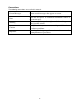
Conventions The following conventions are used in this manual . Screen Messages Note Warning Caution Important Denote actual messages that appear on screen. Give bits and pieces of additional information related to the current topic. Alert you any damage that might result form doing or not doing specific actions. Give precautionary measures to avoid possible hardware or software problems. Remind you doing specific actions relevant to the accomplishment of procedures.
Table of Contents 1 2 3 System Introduction .......................................................................................................................1 1.1 Technical Specification ............................................................................................................1 1.2 Location of features, Controls, and I/O ..................................................................................2 1.3 System Block Diagram .....................................................
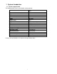
1 System Introduction 1.1 Technical Specification The following tables list the specifications for the projector. Metric Dimensions Height Width Depth Weight Contrast ratio Brightness Light source Resolution Zoom focus Display technology Projection screen Projection distance Noise Power consumption I/O connectors 4.0 cm 11.1 cm 9.3 cm <1lb(390g) 800:1 100 lumens Red/green/blue LED module SVGA(858×600) Fixed zoom/manual focus 0.45-inch DLP 15.0 to 60-inch 8.5 feet (2.
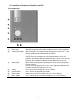
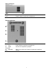
1.2 Location of features, Controls, and I/O Top components Component (1) Focus ring (2) Temperature light Description Move the ring to the left or right to adjust the focus of the projector. When the light is on, Indicates that temperature is over 47.5 ℃ and that the projector will automatically shut down. NOTE: Excessive temperature may indicate that the vents are blocked. To maintain optimal temperature, be sure the vents are not blocked. Also, allow the projector to cool down after it turns off.
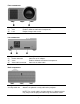
Front components Component (1) Vent (2) Lens Description Enables airflow to cool internal components. Projects images onto screen. Left components Component (1) Power connector (2) Vents (3) Video cable connector Description Connects an AC adapter. Enables airflow to cool internal components. Connects the video cable. Back components Component Security cable slot Description Attaches an optional security cable to the projecto r.
Right components Component Vents Description Enables airflow to cool internal components. Bottom components Component (1) Vents (2) Tripod connector (3) Adjustable foot Description Enable airflow to cool internal components. Connects the tripod to the projector. Allows you to adjust the height of the projector for optimum viewing.
1.
2 Firmware Upgraded Flow This chapter provides the information regarding relevant eq uipments and upgrading procedure for firmware upgrade. Note: Firmware upgrade process is not necessary. Please check the firmware and composer version before any procedures. During firmware download period, please do not shut down PC or projector, this will cause flash memory’s damage. And need to return the unit to manufacturer for flash memory recovery. 2.1 Setup Tool/Equipment 1. Computer 2. USB upgrading cable 3.
USB Support - Installation (All Platforms) This release includes support for a USB communications interface to DDP2000-based projectors. The setup program includes the files needed to install USB support (for Windows 98/Me/2000/XP only --- Win95 and WinNT are not supported). After DLP Composer™ Lite is installed, to install the USB support, choose the "Install DDP2000 USB Driver" icon under "DLP Composer™ Lite" in your Start menu.
Operating procedure 1. Connect the Projector and PC via USB cable. 2. Double-click [DLP Composer (TM) Lite]. The following screen will appear. 3. Select [Edit]/[Preferences]/[Communications] to check USB in [Projector Interface]. 4. Click [USB Device Identification]. 5. Set the items on the [Vendor 0x451, Product 0x2000]. 6. Click [OK] 7. Move the cursor to [Flash Loader] on the Project window of [DLP Composer Lite]. (The [Flash Loader] screen will appear.) 8.
2. Put checkmark next to [Skip Boot Loader Area],VALUE SETTING 32KB. 1. Click [Browse] and select [*.img] 4. Click [Start Download] 3. Click [Reset Bus] to confirm the USB connection is ok. Click [Yes(是)] 12. Wait for the Completion of upgrading, and then remove AC Adapter, Power Cord and upgrading cable.
3 Machine Disassembly and Replacement 3.1 Tools Item Photo Long Nose Nipper Nipper Screw Bit(+):2*5*40 Screw Bit(+):2*4*60 Anti-static wrist strap Anti-static wrist gloves 3.2 Disassembly Procedure Warning Put on the Static Electricity Ring when starting for repair. Repair Environment suggest in Clean-room class 10000. Do not remove Optical Engine or DMD panel outside the clean room. While screwing or unscrewing screws, please keep the screwdriver straight.
Step Figure Description 1 1. Press the power button to shutdown the projector and disconnect the AC Adapter and power cord. 2 Loosen the screws J1635-2684-00*4 as shown. J1635-2684-00*2 J1635-2684-00*2 3 Raise the top cover gently and disconnect the keypad FFC between the top cover and main board.
4 Loosen the three screws J1635-3177-00*3 for moving Bottom Cover. J1635-3177-00*3 5 J1635-2021-00*2 6 Loosen the three screws J1635-2021-00*2 to remove the DC Fan J2394-0103-00. Loosen J1635-3184-00*1. J1635-3184-00*1 7 J1635-3177-00*3 1. Loosen J1635-3177-00*3. 2. Remove all the wires on the Main board. 3. Remove Main board.
8 Loosen screws J1635-2687-00*2 to remove the Focus-ring. J1635-2687-00*2 9 J1635-3177-00*4 13 Loosen the four screws J1635-3177-00*4 to remove the DMD board.
3.3 Mechanical Drawing 1. Front Cover 2. Top Cover 3. Back Cover 4. Focus Ring 6. Optical Engine 7. Fan 5. DMD Board 8. OE Fan 9. Main Board 10. Bottom Cover 11.
4 Troubleshooting and Verifying the Repair This chapter provides technicians and people who have an electronic background a primary description about maintaining the product. Moreover, you can get the appropriate operation to solve some complicated problems of component repairing and professional problems. 4.1 Troubleshooting Warning: Do not directly look into the lens to avoid eyesight damages. The projector is equipped with ventilation holes (intake) and ventilation holes (exhaust).
Power Source Troubleshooting No Power Source after turning on Check AC socket and connector Fan failure after turning on NG Check Fan connection Replace AC NG Reconnect fan NG Replace fan NG Replace Main board socket OK OK Check Fan Check LED and keypad FPC Replace NG keypad PFC OK OK Check Main board and power cable Check Main board Replace NG power cable OK Replace Main board 16
Video Signal Troubleshooting Computer Video No No Signal Signal Check NG Source Turn on Check source Source NG Cable Replace Check Cable Replace NG Check DMD board Replace Cable NG DMD board OK Replace DMD board OK NG Main board Replace Check Main board NG Main board OK Check Optical Engine NG OK DMD board Check source Cable OK Check Turn on OK OK Check NG Replace Main board OK NG Replace Optical Engine Check Optical Engine 17 NG Replace Optical Engine
Image Color abnormal abnormal Power on again and reset OSD Check input cable and signal setting OK Check input cable and signal setting NG Adjust Input Signal OK NG Adjust Input Check Signal NG Replace DMD board DMD board OK Check NG DMD board Replace Check DMD board NG Main board OK Check Main board Main board OK NG Replace Check Optical engine Main board OK Check Optical engine Replace NG Replace Optical engine 18 NG Replace Optical engine
Operation Function Troubleshooting Button Failure Check Keypad and FFC NG Replace Keypad and FFC OK Check NG Main board 4.2 Replace Main board Verifying the Repair After repairing projector (Dissembling and assembling projector), Repair center should verify the quality of repaired unit. Here is a general guide for all repaired model. That means if the projector is without S-Video port, repair center can skip the portion of S-Video verification.
(2) Operation test Buttons operation Button description Power Test criteria 1. Mechanical motion (Up & Down) should be free from getting stuck when pressing the button. 2. Press “power” button and projector will switch on. Menu &Enter 1. Mechanical motion (Up & Down) should be free from getting stuck when pressing the button. 2. Press Menu &Enter button can make projector function normally. 4-way button (Auto/Source) 1.
Full darkness Light leak in active area and colorific light leak in inactive area are not allowable. Twelve Grids Press “AUTO” button, more than three twinkling grids are not allowable. (It allows to press “AUTO” less than four times.) 16 Gray Level 16 level of gray level color should be distinguishable and no defection. Gray 10 1. The quantity of blemish in the active area should be less than four pieces and the diameter of it should be less than 1.5”(about 3.81cm). 2.
256 level RGB --256 level of RGB color should be distinguishable, at least Red color scales should be. -- For each RGB 256 levels, Noise or color deviation in R, G, and B single level respectively are acceptable. Video I/O port Video Test Equipment Standard Pattern generator (Ex. Quantum data)&DVD player Criteria No apparent color deviation on the projected image (4) Resolution I/O port VGA Test Equipment PC Test Method 1. Rotate Zoom ring to wide mode (Maximum projected image) 2.
5 Color Temperature Calibration Warning: . Operate LED Calibration in a dark room (don’t allow any light.)<0.5lux . Projected image size: 30 inches. . The CL-200 is 1.2±0 . 1 mfar from projector. And the drop for measur ement is the center of projected screen. . Computer for operation m ust be Window XP or more advanced. 5.1 Setup Tool/Equipment 1. Computer 2. USB upgrading cable and extended USB cable 3. Power Cord and AC Adaptor 4. CL-200 5.2 Upgrading Procedure 1.
The file type is txt. 5. Input the Bar Code number of projector, then click [Calibration] to start Color Temperature Calibration automatically. Click Calibration 6. The dialog box as below indicates calibration has completed.
7. Click Pass[ ]. 8. Ensure the data of calibration is as same as the projector ’s. If not, please calibrate again. Compare the datas 9. Turn off the projector normally. Don’t cut off the power until it goes out.
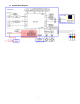
6 Connector Information This section provides each connector location on boards and function of each board. They will be useful for your detecting the defective boards. 6.
7 Spare Parts list Introduction This section is a list of all the FRU removal. Following the FRU table of contents is an enlarged view of the entire projector, which shows the primary FRUs in the projector. When working on the projector, use appropriate anti-static precautions such as anti-static mats, wrist straps and grounded work surfaces. Failure to do this can destroy static-sensitive components and make the product inoperable. 7.1 Board/Module P/N Desc.
Appendix A: Computer Compatibility Mode Resolution fH (kHz) fV (Hz) VGA 640 x 480 31.47 kHz 59.94 Hz VGA 640 x 480 37.86 kHz 72.81 Hz VGA 640 x 480 37.50 kHz 75.00 Hz VGA 640 x 480 43.27 kHz 85.01 Hz SVGA 800 x 600 35.16 kHz 56.25 Hz SVGA 800 x 600 37.88 kHz 60.32 Hz SVGA 800 x 600 48.08 kHz 72.19 Hz SVGA 800 x 600 46.88 kHz 75.00 Hz SVGA 800 x 600 53.67 kHz 85.06 Hz XGA 1024 x 768 48.36 kHz 60.00 Hz XGA 1024 x 768 56.48 kHz 70.07 Hz XGA 1024 x 768 60.