HP EliteBook 8530p Notebook PC HP EliteBook 8530w Mobile Workstation Maintenance and Service Guide
© Copyright 2008, 2009, 2011, 2012 Hewlett-Packard Development Company, L.P. Bluetooth is a trademark owned by its proprietor and used by Hewlett-Packard Company under license. Intel and Core are trademarks or registered trademarks of Intel Corporation in the United States and other countries. Microsoft, Windows, and Windows Vista are either trademarks or registered trademarks of Microsoft Corporation in the United States and/or other countries. SD Logo is a trademark of its proprietor.
Safety warning notice WARNING! To reduce the possibility of heat-related injuries or of overheating the computer, do not place the computer directly on your lap or obstruct the computer air vents. Use the computer only on a hard, flat surface. Do not allow another hard surface, such as an adjoining optional printer, or a soft surface, such as pillows or rugs or clothing, to block airflow.
iv Safety warning notice
Table of contents 1 Product description ........................................................................................................................................ 1 2 External component identification ................................................................................................................ 9 Display components ............................................................................................................................. 9 Top components ...................
Grounding guidelines ......................................................................................................... 40 Electrostatic discharge damage ........................................................................ 40 Packaging and transporting guidelines ............................................. 41 Workstation guidelines ..................................................................... 41 Equipment guidelines .......................................................................
Security menu .................................................................................................................. 100 Diagnostics menu ............................................................................................................ 102 System Configuration menu ............................................................................................ 103 6 Specifications .............................................................................................................
Using the Windows recovery tools .................................................................. 140 Using f11 ......................................................................................................... 140 Using a Windows Vista operating system DVD (purchased separately) ......... 141 Backup and Recovery in Windows XP ............................................................................................. 142 Backing up your information ................................................
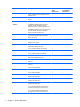
1 Product description Category Description HP EliteBook 8530p Notebook PC Product Name HP EliteBook 8530p Notebook PC √ HP EliteBook 8530w Mobile Workstation Processors HP EliteBook 8530w Mobile Workstation √ Intel® Core™2 Extreme processors QX9300, Quad Core 2.53-GHz processor 12MB L2 cache, 1066-MHz front side bus (FSB) √ X9100, Dual-Core 3.06-GHz processor 6-MB L2 cache, 1066-MHz FSB √ Intel Core2 Quad processors Q9100, 2.26-GHz processor 6-MB L2 cache, 1066-MHz FSB √ Q9000, 2.
Category Chipset Graphics Description HP EliteBook 8530p Notebook PC HP EliteBook 8530w Mobile Workstation P8400, 2.26-GHz processor 3-MB L2 cache, 1066-MHz FSB √ √ Intel PM45 Express Chipset with iAMT 4.
Category Description HP EliteBook 8530p Notebook PC 15.4-in WXGA AntiGlare with webcam for computers with Extreme and Quad CPUs Memory Hard drives HP EliteBook 8530w Mobile Workstation √ Support privacy filter √ √ Two customer-accessible/upgradable memory module slots √ √ Supports dual-channel memory √ √ Supports up to 8 GB of system RAM √ √ PC2-6400, 800-MHz, DDR2 √ √ Supports the following configurations: √ √ Supports 9.5-mm, 6.35-cm (2.
Category Description HP EliteBook 8530p Notebook PC HP EliteBook 8530w Mobile Workstation Upgrade bay Fixed (removal of 1 screw required) √ √ Customer-accessible √ √ Serial ATA √ √ 12.7-mm tray load √ √ Supports the following drives: √ √ Supports external USB diskette drive only √ √ Supports boot from external USB diskette drive √ √ Microphone Integrated dual-array microphone √ √ Audio HD audio - ADI 1984A √ √ Webcam Integrated 2.
Category Description HP EliteBook 8530p Notebook PC HP EliteBook 8530w Mobile Workstation Subscriber identity module (SIM) security (customer-accessible in battery bay) √ √ Support for the following WWAN formats: √ √ ● Evolution-data optimized (EVDO) ● High-speed downlink packet access (HSDPA) Integrated personal area network (PAN) options by way of Bluetooth® module: External media card Ports Docking Keyboard/pointing devices Support for no PAN option √ √ Broadcom Bluetooth √ √ One
Category Description HP EliteBook 8530p Notebook PC HP EliteBook 8530w Mobile Workstation Power requirements AC adapter with localized cable plug support (3-wire plug with ground pin, supports 3-pin DC connector): √ √ 8-cell, 2.55-Ah (73-Wh) Li-ion battery √ √ Support for 8-cell Extended Life Battery √ √ Support for 12-cell Ultra Capacity Battery √ √ Integrated fingerprint reader √ √ Integrated smart card reader √ √ Security cable slot √ √ Trusted platform module (TPM) V.1.
Category Description HP EliteBook 8530p Notebook PC HP EliteBook 8530w Mobile Workstation Windows 7 Professional 32 with Microsoft Office 2007 Professional √ √ Windows 7 Professional 32 with Microsoft Office 2007 Ready √ √ Windows Vista Ultimate 32 with Office 2007 Ready (select regions) √ √ Windows Vista Ultimate 32 with Office 2007 Ready with WWAN (select regions) √ √ Windows Vista Business 64 with Office 2007 Ready √ Windows Vista Business 64 with Office 2007 Ready with WWAN √ Windows
Category Description HP EliteBook 8530p Notebook PC HP EliteBook 8530w Mobile Workstation Windows Vista Business with XP Professional with Office 2007 Personal with WWAN (Japan only) √ √ Windows Vista Business with XP Professional with Office 2007 Personal with PowerPoint (Japan only) √ √ Windows Vista Business with XP Professional with Office 2007 Personal with PowerPoint with WWAN (Japan only) √ √ Windows 7 Professional 32 √ √ Windows Vista Ultimate 32 √ √ Windows Vista Business 32/64
2 External component identification Display components Item Component Function (1) WWAN antennas (2) (select models only)* Send and receive wireless signals to communicate with WWANs. (2) WLAN antennas (3) (select models only)* Send and receive wireless signals to communicate with WLANs. *The antennas are not visible from the outside of the computer. For optimal transmission, keep the areas immediately around the antennas free from obstructions.
Top components Pointing devices Item Component Function (1) Pointing stick Moves the pointer and selects or activates items on the screen. (2) Center pointing stick button Functions like the center button on an external mouse. (3) Right pointing stick button Functions like the right button on an external mouse. (4) TouchPad scroll zone Scrolls up or down. (5) Right TouchPad button Functions like the right button on an external mouse.
Buttons, switches, and fingerprint reader Item Component Function (1) Power button ● When the computer is off, press the button to turn on the computer. ● When the computer is on, press the button to shut down the computer. ● When the computer is in the Sleep state (Windows Vista) or in Standby (Windows XP), press the button briefly to exit the Sleep state or Standby. ● When the computer is in Hibernation, press the button briefly to exit Hibernation.
Item Component Function (3) Wireless button Turns the wireless feature on or off, but does not establish a wireless connection. NOTE: A wireless network must be set up in order to establish a wireless connection. (4) Internal display switch Turns off the display if the display is closed while the power is on. (5) Presentation button Starts the presentation feature. (6) Volume mute button Mutes and restores speaker sound. (7) Volume scroll zone Adjusts speaker volume.
Item Component Function (3) fn key Executes frequently used system functions when pressed in combination with a function key or the esc key. (4) Windows logo key Displays the Windows Start menu. (5) Pointing stick buttons Function like the buttons on an external mouse (6) Windows applications key Displays a shortcut menu for items beneath the pointer. (7) Embedded numeric keypad keys Can be used like the keys on an external numeric keypad.
Item Component Function (3) Battery light ● Amber: A battery is charging. ● Blinking turquoise: A battery is close to full charge capacity. ● Blinking amber: A battery that is the only available power source has reached a low battery level. When the battery reaches a critical battery level, the battery light begins blinking rapidly. ● Off: If the computer is plugged into an external power source, the light turns off when all batteries in the computer are fully charged.
Front components Item Component Function (1) Wireless light ● Turquoise: An integrated wireless device, such as a WLAN device, the HP Mobile Broadband Module, and/or a Bluetooth device, is turned on. ● Amber: All wireless devices are turned off. ● On: The computer is on. ● Blinking: The computer is in the Sleep state (Windows Vista) or in Standby (Windows XP). ● Off: The computer is off or in Hibernation. ● Amber: A battery is charging.
Left-side components Item Component Function (1) USB ports (2) Connect optional USB devices. (2) RJ-45 (network) jack Connects a network cable. NOTE: The RJ-45 (network) jack provides Gigabit Ethernet functionality. (3) Vent Enables airflow to cool internal components. NOTE: The computer fan starts up automatically to cool internal components and prevent overheating. It is normal for the internal fan to cycle on and off during routine operation.
Rear components Item Component Function (1) Power connector Connects an AC adapter. (2) External monitor port Connects an external VGA monitor or projector. Right-side components Item Component Function (1) Audio-out (headphone) jack Produces sound when connected to optional powered stereo speakers, headphones, ear buds, a headset, or television audio. (2) Audio-in (microphone) jack Connects an optional computer headset microphone, stereo array microphone, or monaural microphone.
Bottom components Item Component Function (1) Battery bay Holds the battery and a wireless subscriber identity module (SIM). The SIM slot is located inside the battery bay. NOTE: The battery must be installed for the SIM to operate. (2) Battery release latch Release the battery from the battery bay. (3) Docking connector Connects an optional docking device. (4) Vents (7) Enables airflow to cool internal components.
3 Illustrated parts catalog Service tag When ordering parts or requesting information, provide the computer serial number and model description provided on the service tag. ● Product name (1). This is the product name affixed to the front of the computer. ● Serial number (s/n) (2). This is an alphanumeric identifier that is unique to each product. ● Part number/Product number (p/n) (3). This number provides specific information about the product's hardware components.
Computer major components 20 Item Description (1) Display assembly for use with HP EliteBook 8530p computer models equipped with WLAN and WWAN capability (includes 3 WLAN antenna transceivers and cables and 2 WWAN antenna transceivers and cables) Chapter 3 Illustrated parts catalog Spare part number
Item Description Spare part number 15.4-in, WXGA 495043-001 15.4-in, WSXGA+ 495044-001 15.4-in, WUXGA 495045-001 Display assembly for use with HP EliteBook 8530w computer models equipped with WLAN and WWAN capability (includes 3 WLAN antenna transceivers and cables and 2 WWAN antenna transceivers and cables) 15.4-in, WXGA 495046-001 15.4-in, WSXGA+ 495047-001 15.
Item (2) (3) 22 Description Spare part number Display bezel for use with HP EliteBook 8530w computer models equipped with WLAN and WWAN capability and integrated webcam 506813-001 Display hinges for use with HP EliteBook 8530p computer models 495070-001 Display hinges for use with HP EliteBook 8530w computer models 502334-001 Display inverter 487431-001 Display panel enclosure 600907-001 Display cable 600908-001 Switch cover 495073-001 LED board (includes cable) 501232-001 Keyboard wit
Item (4) Description Spare part number For use in Taiwan 495042-AB1 For use in Thailand 495042-281 For use in Turkey 495042-141 For use in the United Kingdom 495042-031 For use in the United States 495042-001 Top cover NOTE: The top cover spare part kits do not include the fingerprint reader board and cable. The fingerprint reader board and cable are available using spare part number 495063-001.
Item (8) Description Spare part number For use with the Dual-Core processor and nVidia graphics card 495075-001 For use with the Dual-Core processor and ATI graphics card 501117-001 Graphics card (includes replacement thermal material) ATI M86M ATI Mobility Radeon HD 3650 graphics card with 256 MB of graphics subsystem memory (supports Hypermemory) 495081-001 ATI M86M ATI Mobility FireGL V5700 graphics card with 256 MB of graphics subsystem memory (supports Hypermemory) 502337-001 nVidia NB9P-GL
Item Description (11) Modem module Spare part number NOTE: The modem module spare part kit does not include a modem module cable. The modem module cable is included in the Cable Kit, spare part number 495064-001. See Cable Kit on page 28 for more Cable Kit spare part number information.
Item Description (22) WWAN module HP un2400 Mobile Broadband Module (23) Spare part number 483377-001 Broadcom Bluetooth module (does not include Bluetooth module cable) NOTE: The Bluetooth module spare part kit does not include a Bluetooth module cable. The Bluetooth module cable is included in the Cable Kit, spare part number 495064-001. See Cable Kit on page 28 for more Cable Kit spare part number information.
Plastics Kit Item Description Spare part number Plastics Kit: 495076-001 (1) Memory module compartment cover (includes one captive screw, secured by a C-clip) (2) Hard drive cover (includes 2 captive screws, secured by C-clips) (3) Bluetooth module cover (4) Computer feet (4) (5) ExpressCard slot protective insert Plastics Kit 27
Cable Kit Item 28 Description Spare part number Cable Kit: 495064-001 (1) RJ-11 connector cable (2) Microphone (3) USB/audio cable Chapter 3 Illustrated parts catalog
Mass storage devices Item Description (1) Optical drive Spare part number DVD±RW and CD-RW SuperMulti DL Combo Drive with LightScribe 495061-001 Blu-ray Disc ROM with SuperMulti DVD±R/RW DL Drive 495062-001 DVD-ROM Drive 495060-001 (2) Optical drive bracket 502332-001 (3) Hard drive (includes bracket) 500-GB, 7200-rpm 634924-001 500-GB, 5400-rpm 634632-001 320-GB, 7200-rpm 603783-001 250-GB, 7200-rpm 495059-001 160-GB, 7200-rpm 483186-001 160-GB, 7200-rpm (Seagate only) 580297-001
Miscellaneous parts Description Spare part number AC adapters 90-W AC adapter, 3P/RC 463955-001 90-W AC adapter, RC/V EM (for use in India) 535593-001 90-W AC adapter, RC/V 3W 613153-001 90-W AC adapter, RC/V EM 3W (for use only in India) 613160-001 90-W AC adapter, RC/V 3W 620656-001 120-W AC adapter, 3P/RC 463953-001 120-W AC adapter, RC/V 3W 613154-001 150-W AC adapter, 3P/RC 463954-001 150-W AC adapter, RC/V 3W 613156-001 180-W AC adapter, 3P/RC 463952-001 External MultiBay II 366
Description Spare part number For use in the United States 490371-001 Screw Kit 495077-001 ● Phillips PM3.0x5.0 screw ● Phillips PM2.5×9.0 captive screw ● Phillips PM2.5×7.0 screw ● Phillips PM2.5×5.0 screw ● Phillips PM2.5×3.0 screw ● Phillips PM2.0×11.0 captive screw ● Phillips PM2.0×5.0 captive screw ● Phillips PM2.0×5.0 screw ● Phillips PM2.0×4.0 barrel screw ● Phillips PM2.0×3.0 screw ● Phillips PM2.0×3.0 broadhead screw ● Torx T8M2.5x12.0 captive screw ● Torx T8M2.5x8.
32 Spare part number Description 480986-001 Intel Wi-Fi Link 5300 802.11a/b/g/n 3x3 WLAN module with iAMT 4.
Spare part number Description 495042-091 Keyboard with pointing stick for use in Norway (includes keyboard and pointing stick cables) 495042-121 Keyboard with pointing stick for use in French Canada (includes keyboard and pointing stick cables) 495042-131 Keyboard with pointing stick for use in Portugal (includes keyboard and pointing stick cables) 495042-141 Keyboard with pointing stick for use in Turkey (includes keyboard and pointing stick cables) 495042-161 Keyboard with pointing stick for us
34 Spare part number Description 495048-001 15.4-in WUXGA display assembly for use with HP EliteBook 8530w computer models equipped with WLAN and WWAN capability (includes 3 WLAN antenna transceivers and cables and 2 WWAN antenna transceivers and cables) 495049-001 15.
Spare part number Description 500907-001 System board for use in HP EliteBook 8530p and 8530w models with Intel Core2 Duo processors 501106-001 Intel Core2 Extreme X9100, 3.06-GHz processor (6-MB L2 cache, 1066-MHz FSB) 501107-001 Intel Core2 Extreme QX9300, 2.
36 Spare part number Description 506811-001 15.
Spare part number Description 598861-001 1-GB memory module (PC2-6400, 800-MHz, DDR2) 600907-001 Display panel enclosure 600908-001 Display cable 603783-001 320-GB, 7200-rpm hard drive (includes hard drive bracket) 613153-001 90-W AC adapter, RC/V 3W 613154-001 120-W AC adapter, RC/V 3W 613156-001 150-W AC adapter, RC/V 3W 613160-001 90-W AC adapter, RC/V EM 3W for use only in India 618809-001 Intel Core2 Duo T9900, 3.
4 Removal and replacement procedures Preliminary replacement requirements Tools required You will need the following tools to complete the removal and replacement procedures: ● Flat-bladed screwdriver ● Phillips P0 and P1 screwdrivers ● Torx T8 screwdriver Service considerations The following sections include some of the considerations that you must keep in mind during disassembly and assembly procedures.
Cables and connectors CAUTION: When servicing the computer, be sure that cables are placed in their proper locations during the reassembly process. Improper cable placement can damage the computer. Cables must be handled with extreme care to avoid damage. Apply only the tension required to unseat or seat the cables during removal and insertion. Handle cables by the connector whenever possible. In all cases, avoid bending, twisting, or tearing cables.
Grounding guidelines Electrostatic discharge damage Electronic components are sensitive to electrostatic discharge (ESD). Circuitry design and structure determine the degree of sensitivity. Networks built into many integrated circuits provide some protection, but in many cases, ESD contains enough power to alter device parameters or melt silicon junctions. A discharge of static electricity from a finger or other conductor can destroy static-sensitive devices or microcircuitry.
Packaging and transporting guidelines Follow these grounding guidelines when packaging and transporting equipment: ● To avoid hand contact, transport products in static-safe tubes, bags, or boxes. ● Protect ESD-sensitive parts and assemblies with conductive or approved containers or packaging. ● Keep ESD-sensitive parts in their containers until the parts arrive at static-free workstations. ● Place items on a grounded surface before removing items from their containers.
Equipment guidelines Grounding equipment must include either a wrist strap or a foot strap at a grounded workstation. ● When seated, wear a wrist strap connected to a grounded system. Wrist straps are flexible straps with a minimum of one megohm ±10% resistance in the ground cords. To provide proper ground, wear a strap snugly against the skin at all times. On grounded mats with banana-plug connectors, use alligator clips to connect a wrist strap.
Component replacement procedures This chapter provides removal and replacement procedures. There are as many as 97 screws and screw locks, in 17 different sizes, that must be removed, replaced, or loosened when servicing the computer. Make special note of each screw and screw lock size and location during removal and replacement. Service tag When ordering parts or requesting information, provide the computer serial number and model description provided on the service tag. ● Product name (1).
Computer feet The computer feet are adhesive-backed rubber pads. The feet are included in the Plastics Kit, spare part number 495076-001. There are 4 rubber feet that attach to the base enclosure in the locations illustrated below.
Battery Description Spare part number 8-cell, 2.55-Ah (73-Wh) Li-ion battery for use in all countries and regions except Japan 493976-001 8-cell, 2.55-Ah (73-Wh) Li-ion battery for use in Japan 534057-291 Before disassembling the computer, follow these steps: 1. Shut down the computer. If you are unsure whether the computer is off or in Hibernation, turn the computer on, and then shut it down through the operating system. 2. Disconnect all external devices connected to the computer. 3.
SIM NOTE: This section applies only to computer models with WWAN capability. NOTE: If there is a SIM inserted in the SIM slot, it must be removed before disassembling the computer. Be sure that the SIM is reinserted in the SIM slot after reassembling the computer. Before removing the SIM, follow these steps: 1. Shut down the computer. If you are unsure whether the computer is off or in Hibernation, turn the computer on, and then shut it down through the operating system. 2.
Optical drive NOTE: All optical drive spare part kits include an optical drive bezel. Description Spare part number DVD±RW and CD-RW SuperMulti DL Combo Drive with LightScribe 495061-001 Blu-ray Disc ROM with SuperMulti DVD±R/RW DL Drive 495062-001 DVD-ROM Drive 495060-001 Optical drive bracket 502332-001 Before removing the optical drive, follow these steps: 1. Shut down the computer.
6. Remove the two Phillips PM2.0×3.0 screws (1) that secure the optical drive bracket to the optical drive. 7. Remove the optical drive bracket (2). Reverse this procedure to install an optical drive.
Display inverter NOTE: If it has been determined that the display inverter is the component that must be replaced to complete the computer repair, the display assembly does not have to be removed. Follow the procedures in this section to replace the display inverter. For information on replacing the display assembly and the display hinges, see Display assembly on page 69.
6. Release the display bezel bottom edge (3) from the display assembly. 7. Remove the two Phillips PM2.5×5.0 screws (1) that secure the display inverter to the display enclosure. 8. Release the inverter (2) from the display enclosure as far as the display panel cable and backlight cable allow. 9. Disconnect the backlight cable (3) and the display panel cable (4) from the display inverter. 10. Remove the display inverter. Reverse this procedure to install the display inverter.
Hard drive NOTE: All hard drive spare part kits include a hard drive bracket.
52 3. Lift the right side of the hard drive cover (2), swing it to left, and remove the cover. The hard drive cover is included in the Plastics Kit, spare part number 495076-001 4. Loosen the Phillips PM2.5×11.0 captive screw (1) that secures the hard drive to the computer. 5. Grasp the Mylar tab (2) on the hard drive and slide the hard drive (3) to the left to disconnect it from the system board. 6. Remove the hard drive (4) from the hard drive bay. 7.
8. Lift the bracket (2) straight up to remove it from the hard drive. Reverse this procedure to reassemble and install the hard drive.
Bluetooth module NOTE: The Bluetooth module spare part kit does not include a Bluetooth module cable. The Bluetooth module cable is included in the Cable Kit, spare part number 495064-001. See Cable Kit on page 28 for more Cable Kit spare part number information. Description Spare part number Bluetooth module for use in all countries and regions 483113-001 Before removing the Bluetooth module, follow these steps: 1. Shut down the computer.
Reverse this procedure to reassemble and install the Bluetooth module. RTC battery Description Spare part number RTC battery 501115-001 Before removing the RTC battery, follow these steps: 1. Shut down the computer. If you are unsure whether the computer is off or in Hibernation, turn the computer on, and then shut it down through the operating system. 2. Disconnect all external devices connected to the computer. 3.
5. Slide the RTC battery (2) out of the rubber pouch on the bottom of the system board. Reverse this procedure to install the RTC battery.
Memory modules Description Spare part number 1-GB (PC2-6400, 800-MHz, DDR2) 598861-001 2-GB (PC2-6400, 800-MHz, DDR2) 598858-001 4-GB (PC2-6400, 800-MHz, DDR2) 598855-001 Before removing the expansion memory module, follow these steps: 1. Shut down the computer. If you are unsure whether the computer is off or in Hibernation, turn the computer on, and then shut it down through the operating system. 2. Disconnect all external devices connected to the computer. 3.
5. Remove the expansion memory module (2) by pulling the module away from the slot at an angle. NOTE: Memory modules are designed with a notch (3) to prevent incorrect insertion into the memory module slot. Reverse this procedure to install an expansion memory module. Remove the primary memory module: 1. Spread the retaining tabs (1) on each side of the primary memory module slot to release the memory module. (The edge of the module opposite the slot rises away from the computer.) 2.
WWAN module CAUTION: The WWAN module and the WLAN module are not interchangeable. Description Spare part number HP un2400 Mobile Broadband Module 483377-001 Before removing the WWAN module, follow these steps: 1. Shut down the computer. If you are unsure whether the computer is off or in Hibernation, turn the computer on, and then shut it down through the operating system. 2. Disconnect all external devices connected to the computer. 3.
5. Remove the WWAN module (3) by pulling the module away from the slot at an angle. NOTE: WWAN modules are designed with a notch (4) to prevent incorrect insertion. Reverse this procedure to install the WWAN module.
Keyboard For use in: Spare part number For use in: Spare part number Keyboards with pointing stick (includes pointing stick cable): Belgium 495042-A41 The Netherlands and Europe 495042-B31 Brazil 495042-201 Norway 495042-091 The Czech Republic 495042-221 Portugal 495042-131 Denmark 495042-081 Russia 495042-251 France 495042-051 Saudi Arabia 495042-171 French Canada 495042-121 Slovakia 495042-231 Germany 495042-041 Slovenia 495042-BA1 Greece 495042-DJ1 Spain 495042-071 Hun
62 2. Loosen the two Phillips PM2.5×9.0 captive screws that secure the keyboard to the computer. 3. Turn the computer right-side up, with the front toward you. 4. Open the computer as far as possible. 5. Slide the four keyboard retention tabs (1) toward you. The tabs are located between the esc and f1 keys, between the f4 and f5 keys, between the f8 and f9 keys, and between the f12 and scroll keys. 6.
8. Release the ZIF connector (3) to which the pointing stick cable is attached, and disconnect the pointing stick cable (4) from the system board. 9. Remove the keyboard. Reverse this procedure to install the keyboard.
Modem module NOTE: The modem module spare part kit does not include a modem module cable. The modem module cable is included in the Cable Kit, spare part number 495064-001. See Cable Kit on page 28 for more Cable Kit spare part number information. Description Spare part number Modem module 461750-001 Modem module for use in Asia Pacific and Japan 461750-011 Before removing the modem module, follow these steps: 1. Shut down the computer.
4. Disconnect the modem module cable (3) from the modem module. Reverse this procedure to install the modem module. WLAN module CAUTION: The WLAN module and the WWAN module are not interchangeable. Description Spare part number Intel Wi-Fi Link 5100 802.11a/b/g/n 1x2 WLAN module with iAMT 4.
4. Remove the battery (see Battery on page 45). 5. Remove the keyboard (see Keyboard on page 61). Remove the WLAN module: 1. Turn the computer right-side up, with the front toward you. 2. Disconnect the WLAN antenna cables (1) from the terminals on the WLAN module. NOTE: The black WLAN antenna cable is connected to the WLAN module “Main” terminal. The white WLAN antenna cable is connected to the WLAN module “Aux” terminal. If the computer is equipped with an 802.
4. Remove the battery (see Battery on page 45). 5. Remove the keyboard (see Keyboard on page 61). Remove the switch cover: 1. Turn the computer upside-down, with the rear toward you. 2. Remove the three Phillips PM2.0×2.0 broadhead screws that secure the switch cover to the computer. 3. Turn the computer right-side up, with the front toward you. 4. Open the computer as far as possible. 5.
7. Disconnect the LED board cable (1) from the ZIF connector on the system board, and then remove the switch cover from the computer (2). Reverse this procedure to install the switch cover.
Display assembly Description Spare part number Display assemblies for use with HP EliteBook 8530p computer models equipped with WLAN and WWAN capability (includes 3 WLAN antenna transceivers and cables and 2 WWAN antenna transceivers and cables) 15.4-in, WXGA 495043-001 15.4-in, WSXGA+ 495044-001 15.
3. Disconnect the power from the computer by first unplugging the power cord from the AC outlet and then unplugging the AC adapter from the computer. 4. Remove the battery (see Battery on page 45). 5. Disconnect the wireless antenna cables from the WLAN module (see WLAN module on page 65) and the WWAN module (see WWAN module on page 59). 6. Remove the following components: a. Keyboard (see Keyboard on page 61) b. Switch cover (see Switch cover on page 66) Remove the display assembly: 70 1.
5. Remove the following: (1) One round screw cover on each side (2) One large round screw cover and one wedge screw cover on each side (3) Four Torx T8M2.5×7.0 screws (4) One Phillips PM2.5×5.0 screw in the battery bay 6. Remove the two Torx T8M2.5×7.0 screws (1) that secure the display assembly to the computer.
7. Lift the display assembly (2) straight up and remove it. CAUTION: When installing the display assembly, be sure that the 4 wireless antenna cables routed out of the display right hinge are routed and arranged properly. Each antenna cable has an exposed section of cable and a metallic grounding sleeve (1). The grounding sleeve must completely cover the exposed section of cable. Each cable must be secured inside a space in the copper grounding clip (2).
8. If it is necessary to replace the display bezel or display hinges, remove the following: (1) Four rubber screw covers on the display bezel top edge (2) Two rubber screw covers on the display bezel bottom edge (3) Four Phillips PM2.5×7.0 screws on the display bezel top edge (4) Two Phillips PM2.5×7.0 screws on the display bezel bottom edge NOTE: See Display inverter on page 49 for display inverter replacement instructions. 9.
11. If it is necessary to replace the display hinges, remove the four Phillips PM2.5×5.0 screws (1) that secure each display hinge to the display panel. 12. Remove the display hinges (2). The left and right display hinges are available using spare part number 495070-001. 13. Remove the two Phillips PM2.5×5.0 screws (1) that secure the display panel to the display enclosure. The enclosure is available using spare part number 600907-001. The display cable is available using spare part number 600908-001.
14. Remove the display panel (2). Reverse this procedure to reassemble and install the display assembly.
Top cover Description Spare part number For use with computer models with Core2 Duo or Extreme Dual-Core processors 502335-001 For use with HP EliteBook 8530w computer models with Quad Core processors 502336-001 For use with HP EliteBook 8530p computer models 495068-001 Fingerprint reader board (includes fingerprint reader board cable) 495063-001 Before removing the top cover, follow these steps: 1. Shut down the computer.
4. Remove the four Phillips PM 2.0x3.0 broadhead screws (3) 5. Turn the computer right-side up, with the rear toward you. 6. Remove the four Torx T8M2.5×8.0 screws (1) and the two HM2.5×6.0 screw locks (2) that secure the top cover to the computer. 7. Remove the microphone cable from the routing path in the top cover, and then disconnect the microphone cable from the system board.
8. Disconnect the TouchPad board ZIF cable (1) and the fingerprint reader board ZIF cable (2) from the system board. 9. Lift the rear edge of the top cover (1) and swing it up and forward until it rests at an angle. 10. Remove the top cover (2). Reverse this procedure to install the top cover.
TouchPad NOTE: All TouchPad spare part kits include a TouchPad cable. The TouchPad cable is also included in the Cable Kit, spare part number 495064-001. Description Spare part number With 3 TouchPad buttons and 3 pointing stick buttons for use with keyboards with pointing stick 506807-001 Before removing the TouchPad, follow these steps: 1. Shut down the computer. If you are unsure whether the computer is off or in Hibernation, turn the computer on, and then shut it down through the operating system.
3. Slide the bracket forward and remove it, routing the cable through the opening in the bracket. 4. Disconnect the TouchPad cable (1) from the system board. 5. Remove the TouchPad (2). Reverse this procedure to install the TouchPad.
Fan Description Spare part number For use with HP EliteBook 8530p computer models or HP EliteBook 8530w computer models 495079-001 For use with HP EliteBook 8530w computer models with Intel QX9300 Quad Core processor 495080-001 Before removing the fan, follow these steps: 1. Shut down the computer. If you are unsure whether the computer is off or in Hibernation, turn the computer on, and then shut it down through the operating system. 2. Disconnect all external devices connected to the computer.
Reverse this procedure to install the fan. NOTE: To properly ventilate the computer, allow at least a 7.6-cm (3-in) clearance on the left side of the computer. The computer uses an electric fan for ventilation. The fan is controlled by a temperature sensor and is designed to turn on automatically when high temperature conditions exist.
Heat sink Description Spare part number Heat sink (includes a heat sink clip and replacement thermal material) Thermal Material Kits For use with the Quad Core processor and nVidia graphics card 501116-001 For use with the Quad Core processor and ATI graphics card 495074-001 For use with the Dual-Core processor and nVidia graphics card 495075-001 For use with the Dual-Core processor and ATI graphics card 501117-001 Before removing the heat sink, follow these steps: 1. Shut down the computer.
2. Remove the four Torx T8M2.0x7.0 captive screws (1) and the four Torx T8M2.5×12.0 captive screws (2) that secure the heat sink to the base enclosure. 3. Lift the right side of the heat sink (1) to disengage it from the graphics card. 4. Remove the heat sink (2) by sliding it to the right.
Reverse this procedure to install the heat sink.
Processor NOTE: All processor spare part kits include replacement thermal material. The Thermal Material Kit is also available using spare part numbers 501117-001 (for use with Dual-Core processor and ATI graphics card), 495075-001 (for use with Dual-Core processor and nVidia graphics card), 495074-001 (for use with Quad Core processor and ATI graphics card), and 501116-001 (for use with Quad Core processor and nVidia graphics card), Description Spare part number Intel Core2 Extreme QX9300, 2.
e. Display assembly (see Display assembly on page 69) f. Top cover (see Top cover on page 76) g. Fan (see Fan on page 81) h. Heat sink (see Heat sink on page 83) Remove the processor: 1. Position the computer right-side up, with the front toward you. 2. Use a flat-bladed screwdriver to turn the processor locking screw (1) one-half turn counterclockwise until you hear a click. 3. Lift the processor (2) straight up and remove it.
Description Spare part number For use with the ATI Dual-Core processor 501117-001 For use with the nVidia Quad Core processor 495075–001 Before removing the graphics card, follow these steps: 1. Shut down the computer. If you are unsure whether the computer is off or in Hibernation, turn the computer on, and then shut it down through the operating system. 2. Disconnect all external devices connected to the computer. 3.
3. Remove the graphics card (2) by sliding it away from the graphics card slot at an angle. NOTE: The graphics card is designed with a notch (3) to prevent incorrect insertion. Reverse this procedure to install the graphics card. Speaker assembly Description Spare part number Speaker assembly 495072-001 Before removing the speaker assembly, follow these steps: 1. Shut down the computer.
Remove the speaker assembly: 1. Position the computer right-side up, with the front toward you. 2. Disconnect the speaker cable (1) from the system board. 3. Remove the two Torx PM2.5×7.0 screws (2) that secure the speaker assembly to the base enclosure. 4. Remove the speaker assembly (3) from the base enclosure. Reverse this procedure to install the speaker assembly. System board NOTE: All system board spare part kits include replacement thermal material.
Before removing the system board, follow these steps: 1. Shut down the computer. If you are unsure whether the computer is off or in Hibernation, turn the computer on, and then shut it down through the operating system. 2. Disconnect all external devices connected to the computer. 3. Disconnect the power from the computer by first unplugging the power cord from the AC outlet and then unplugging the AC adapter from the computer. 4. Remove the battery (see Battery on page 45). 5.
2. Disconnect the following cables from the system board: (1) RJ-11 connector cable (2) USB/audio board cable (3) Bluetooth module cable 3. Position the base enclosure with the rear panel toward you. 4. Remove the one black Phillips PM2.0×3.0 screw (1) that secures the system board frame to the base enclosure. 5. Lift the system board (2) and frame and slide them to the right (3) to remove them from the base enclosure.
RJ-11 connector cable NOTE: The RJ-11 connector cable is included in the Cables Kit, spare part number 452198-001. Before removing the RJ-11 connector cable, follow these steps: 1. Shut down the computer. If you are unsure whether the computer is off or in Hibernation, turn the computer on, and then shut it down through the operating system. 2. Disconnect all external devices connected to the computer. 3.
3. Remove the RJ-11 connector cable from the clips and routing channel (2) built into the base enclosure. 4. Remove the RJ-11 connector cable from the base enclosure. Reverse this procedure to install the RJ-11 connector cable. ExpressCard assembly Description Spare part number ExpressCard assembly 495085-001 Before removing the ExpressCard assembly, follow these steps: 94 1. Shut down the computer.
h. Heat sink (see Heat sink on page 83) i. Modem module (see Modem module on page 64) j. System board (see System board on page 90) Remove the ExpressCard assembly: 1. Turn the system board upside-down, with the front toward you. 2. Remove the four Phillips PM2.0×5.0 screws that secure the ExpressCard assembly to the system board. 3. Detach the slots on the ExpressCard assembly from the tabs on the ExpressCard connector (1). 4. Remove the ExpressCard assembly (2).
USB/audio board Description Spare part number USB/audio board (includes USB cable and audio cable) 495065-001 Before removing the USB/audio board, follow these steps: 1. Shut down the computer. If you are unsure whether the computer is off or in Hibernation, turn the computer on, and then shut it down through the operating system. 2. Disconnect all external devices connected to the computer. 3.
4. Lift the left side of the USB/audio board (3) until the USB and audio connectors disengage from the openings in the base enclosure. 5. Remove the USB/audio board and cables from the base enclosure. Reverse this procedure to install the USB/audio board.
5 Computer Setup Starting Computer Setup Computer Setup is a preinstalled, ROM-based utility that can be used even when the operating system is not working or will not load. NOTE: Some of the Computer Setup menu items listed in this guide may not be supported by your computer. NOTE: An external keyboard or mouse connected to a USB port can be used with Computer Setup only if USB legacy support is enabled. To start Computer Setup, follow these steps: 98 1.
Using Computer Setup Navigating and selecting in Computer Setup The information and settings in Computer Setup are accessed from the File, Security, Diagnostics, and System Configuration menus. To navigate and select in Computer Setup, follow these steps: 1. Turn on or restart the computer, and then press esc while the “Press the ESC key for Startup Menu” message is displayed at the bottom of the screen.
3. Use a pointing device or the arrow keys to select File > Restore defaults. 4. Follow the on-screen instructions. 5. To save your changes and exit, click the Save icon in the lower-left corner of the screen, and then follow the on-screen instructions. – or – Use the arrow keys to select File > Save changes and exit, and then press enter. Your changes go into effect when the computer restarts. NOTE: Your password settings and security settings are not changed when you restore the factory settings.
Select To do this User Management (requires a BIOS administrator password) ● Create a new BIOS user account. ● View a list of ProtectTools users. Password Policy (requires a BIOS administrator password) Revise password policy criteria. HP SpareKey Enable/disable HP SpareKey (enabled by default). Always Prompt for HP SpareKey Enrollment Enable/disable HP SpareKey enrollment (enabled by default).
Diagnostics menu Select To do this System Diagnostics menu ● 102 Chapter 5 Computer Setup F1 System Information—Displays the following information: ◦ Identification information for the computer and the batteries in the system. ◦ Specification information for the processor, cache and memory size, system ROM, video revision, and keyboard controller version. ● F2 Start-up Test—Verifies the system components needed for starting the computer.
System Configuration menu NOTE: Some of the listed System Configuration options may not be supported by your computer. Select To do this Language Change the Computer Setup language. Boot Options ● Set a Startup Menu delay (in seconds). ● Enable/disable Custom Logo (disabled by default). ● Enable/disable Display Diagnostic URL (enabled by default). ● Enable/disable CD-ROM boot (enabled by default). ● Enable/disable SD Card boot (enabled by default).
Select To do this NOTE: Availability of the options above varies by computer model. Built-In Device Options 104 Chapter 5 Computer Setup ● Enable/disable secondary battery fast charge (enabled by default). ● Enable/disable HP QuickLook 2 (enabled by default). ● Enable/disable Virtualization Technology (select models only; disabled by default). ● Enable/disable TXT (Intel Trusted Execution Technology) (select models only; disabled by default).
Select To do this Port Options (all are enabled by default) NOTE: All port options are enabled by default. ● Enable/disable the Smart Card slot. ● Enable/disable the ExpressCard slot. ● Enable/disable the serial port. ● Enable/disable the parallel port. ● Enable/disable the flash media reader. ● Enable/disable the USB port. CAUTION: Disabling the USB port also disables MultiBay devices and ExpressCard devices on the advanced port replicator. ● AMT Options Enable/disable the 1394 port.
6 Specifications Computer specifications Metric U.S. Length 26.0 cm 10.24 in Width 35.7 cm 14.00 in Height (front to rear) 2.8 to 3.4 cm 1.10 to 1.34 in Weight (equipped with optical drive, 8-cell battery, one 512MB memory module, pointing stick, and TouchPad) 2.77 kg 6.1 lbs Dimensions Input power Operating voltage 19.0 V dc @ 4.74 A – 90 W Operating current 4.
Metric Nonoperating U.S. 1.50 g zero-to-peak, 10 Hz to 500 Hz, 0.5 oct/min sweep rate NOTE: Applicable product safety standards specify thermal limits for plastic surfaces. The computer operates well within this range of temperatures. 15.4-in, WUXGA display specifications Metric U.S. Height 20.7 cm 8.15 in Width 33.1 cm 13.03 in Diagonal 39.1 cm 15.39 in Number of colors Up to 16.
15.4-in, WSXGA+ display specifications Metric U.S. Height 20.7 cm 8.15 in Width 33.1 cm 13.03 in Diagonal 39.1 cm 15.39 in Number of colors Up to 16.8 million Contrast ratio 200:1 (typical) Brightness 180 nits (typical) Dimensions Pixel resolution Pitch 0.197 × 0.197 mm Format 1680 × 1050 Configuration RGB vertical stripe Backlight CCFT Character display 80 × 25 Total power consumption 7.
15.4-in, WXGA display specifications Metric U.S. Height 20.7 cm 8.15 in Width 33.1 cm 13.03 in Diagonal 39.1 cm 15.39 in Number of colors Up to 16.8 million Contrast ratio 200:1 (typical) Brightness 180 nits (typical) Dimensions Pixel resolution Pitch 0.197 × 0.197 mm Format 1366 × 768 Configuration RGB vertical stripe Backlight CCFT Character display 80 × 25 Total power consumption 7.0 W Viewing angle +/-40 horizontal, +/–50° vertical (typical) 15.
Hard drive specifications 500-GB* 320-GB* 250-GB* 160-GB* Height 9.5 mm 9.5 mm 9.5 mm 9.
DVD±RW and CD-RW SuperMulti DL Combo Drive specifications Applicable disc Center hole diameter Read: Write: CD-DA, CD+(E)G, CD-MIDI, CD-TEXT, CDROM, CD-ROM XA, MIXED MODE CD, CD-I, CD-I Bridge (Photo-CD, Video CD), Multisession CD (Photo-CD, CD-EXTRA, Portfolio, CD-R, CD-RW), CD-R, CD-RW, DVDROM (DVD-5, DVD-9, DVD-10, DVD-18), DVDR, DVD-RW, DVD+R, DVD+RW, DVD-RAM CD-R and CD-RW DVD+R, DVD+RW, DVD-R, DVDRW, DVD-RAM 1.5 cm (0.59 in) Disc diameter Standard disc 12 cm (4.72 in) Mini disc 8 cm (3.
Blu-ray Disc ROM Drive with SuperMulti DVD±R/RW Double Layer Applicable disc Read: Write: CD-DA, CD+(E)G, CD-MIDI, CDTEXT, CD-ROM, CD-ROM XA, MIXED MODE CD, CD-I, CD-I Bridge (Photo-CD, Video CD), Multisession CD (Photo-CD, CD-EXTRA, Portfolio, CD-R, CD-RW), CD-R, CD-RW, DVDROM (DVD-5, DVD-9, DVD-10, DVD-18), DVD-R, DVD-RW, DVD+R, DVD+RW, DVD-RAM, HDROM (Single Layer), HD-ROM (Dual Layer), HD DVD-R, HD DVD-R for Dual Layer, HD DVD-RW CD-R and CD-RW DVD+R, DVD+R(9), DVD+RW, DVD-R, DVD-R(9),DVD-RW, DVD-RA
DVD-ROM Drive specifications Applicable disc DVD-ROM (DVD-5, DVD-9, DVD-10, DVD-18, CD-ROM (Mode 1 and 2), CD Digital Audio, CD-XA ready (Mode 2, Form 1 and Form 2), CD-I (Mode 2, Form 1 and Form 2), CD-R, CD-RW, Photo CD (single and multisession), CD-Bridge Center hole diameter 1.5 cm (0.59 in) Disc diameter Standard disc 12 cm (4.72 in) Mini disc 8 cm (3.15 in) Disc thickness 1.2 mm (0.047 in) Track pitch 0.
System DMA specifications Hardware DMA System function DMA0 Not applicable DMA1* Not applicable DMA2* Not applicable DMA3 Not applicable DMA4 Direct memory access controller DMA5* Available for PC Card DMA6 Not assigned DMA7 Not assigned *PC Card controller can use DMA 1, 2, or 5.
System interrupt specifications Hardware IRQ System function IRQ0 System timer IRQ1 Standard 101-/102-Key or Microsoft Natural Keyboard IRQ2 Cascaded IRQ3 Intel 82801DB/DBM USB2 Enhanced Host Controller—24CD IRQ4 COM1 IRQ5* Conexant AC—Link Audio Intel 82801DB/DBM SMBus Controller—24C3 Data Fax Modem with SmartCP IRQ6 Diskette drive IRQ7* Parallel port IRQ8 System CMOS/real-time clock IRQ9* Microsoft ACPI-compliant system IRQ10* Intel USB UHCI controller—24C2 Intel 82852/82855 GM/GME
System I/O address specifications I/O address (hex) System function (shipping configuration) 000 - 00F DMA controller no. 1 010 - 01F Unused 020 - 021 Interrupt controller no.
I/O address (hex) System function (shipping configuration) 220 - 22F Entertainment audio 230 - 26D Unused 26E - 26 Unused 278 - 27F Unused 280 - 2AB Unused 2A0 - 2A7 Unused 2A8 - 2E7 Unused 2E8 - 2EF Reserved serial port 2F0 - 2F7 Unused 2F8 - 2FF Infrared port 300 - 31F Unused 320 - 36F Unused 370 - 377 Secondary diskette drive controller 378 - 37F Parallel port (LPT1/default) 380 - 387 Unused 388 - 38B FM synthesizer—OPL3 38C - 3AF Unused 3B0 - 3BB VGA 3BC - 3BF Rese
System memory map specifications Size Memory address System function 640 KB 00000000-0009FFFF Base memory 128 KB 000A0000-000BFFFF Video memory 48 KB 000C0000-000CBFFF Video BIOS 160 KB 000C8000-000E7FFF Unused 64 KB 000E8000-000FFFFF System BIOS 15 MB 00100000-00FFFFFF Extended memory 58 MB 04800000-07FFFFFF Super extended memory 58 MB 04800000-07FFFFFF Unused 2 MB 08000000-080FFFFF Video memory (direct access) 4 GB 08200000-FFFEFFFF Unused 64 KB FFFF0000-FFFFFFFF System
7 Screw listing This section provides specification and reference information for the screws and screw locks used in the computer. All screws listed in this section are available in the Screw Kit, spare part number 495077-001.
Phillips PM2.0×5.0 captive screw Color Quantity Length Thread Head diameter Black 4 5.0 mm 2.0 mm 4.
Phillips PM2.5×11.0 captive screw Color Quantity Length Thread Head diameter Black 2 11.0 mm 2.5 mm 5.0 mm Where used: One screw that secures the hard drive to the computer Phillips PM2.5×11.
Where used: One screw that secures the optical drive to the computer Phillips PM3.0×5.0 screw Color Quantity Length Thread Head diameter Silver 4 5.0 mm 3.0 mm 5.
Torx T8M2.5×8.0 screw Color Quantity Length Thread Head diameter Black 23 8.0 mm 2.5 mm 5.0 mm Where used: 2 screws that secure the display assembly to the computer Where used: 4 screws that secure the display assembly to the computer Torx T8M2.5×8.
Where used: 8 screws that secure the top cover to the base enclosure Where used: 2 screws that secure the fan to the base enclosure Where used: 2 screws that secure the speaker assembly to the base enclosure 124 Chapter 7 Screw listing
Where used: 1 screw that secures the USB/audio board to the base enclosure Where used: 4 screws that secure the top cover to the top of the computer Torx T8M2.5×8.
Phillips PM2.5×9.0 captive screw Color Quantity Length Thread Head diameter Black 2 9.0 mm 2.5 mm 5.
Black Torx 8M2.0×7.0 captive screw Color Quantity Length Thread Head diameter Black 4 7.0 mm 2.0 mm 4.5 mm Where used: 4 screws that secure the heat sink to the base enclosure Black Torx 8M2.0×7.
Silver Torx 8M2.5×12.0 captive screw Color Quantity Length Thread Head diameter Silver 4 12.0 mm 2.5 mm 4.
Phillips PM2.5×5.0 screw Color Quantity Length Thread Head diameter Black 7 5.0 mm 2.5 mm 5.0 mm Where used: 2 screws that secure the display assembly to the display enclosure Where used: 1 screw that secures each display hinge bracket to the display assembly Phillips PM2.5×5.
Where used: 2 screws that secure the display inverter to the display assembly Where used: 2 screws that secure the display panel to the display enclosure 130 Chapter 7 Screw listing
Phillips PM2.5×3.0 screw Color Quantity Length Thread Head diameter Black 2 3.0 mm 2.5 4.5 mm Where used: 2 screws that secure the WWAN module to the computer Phillips PM2.5×3.
Phillips PM2.0×3.0 broadhead screw Color Quantity Length Thread Head diameter Black 7 3.0 mm 2.0 mm 4.
Black Phillips PM2.0×3.0 screw Color Quantity Length Thread Head diameter Black 9 3.0 mm 2.0 mm 4.5 mm Where used: 4 screws that secure the TouchPad bracket to the top cover Where used: 1 screw that secures the system board to the base enclosure Black Phillips PM2.0×3.
Where used: 2 screws that secure each display hinge to the computer Black Phillips PM2.5×7.0 screw Color Quantity Length Thread Head diameter Black 6 7.0 mm 2.5 mm 5.
Black Phillips PM2.0×4.0 barrel screw Color Quantity Length Thread Head diameter Black 4 4.0 2.0 4.5 Where used: 2 screws that secure the modem module to the system board Where used: 2 screws that secure the WLAN module to the system board Black Phillips PM2.0×4.
Silver HM2.5×6.0 hex screw locks Color Quantity Length Thread Head diameter Silver 2 6.0 mm 2.5 mm 6.
Black Phillips PM2.0×5.0 screw Color Quantity Length Thread Head diameter Black 6 5.0 mm 2.0 mm 4.5 mm Where used: 4 screws that secure the ExpressCard assembly to the system board Where used: 2 screws that secure the graphics card to the system board Black Phillips PM2.0×5.
8 Backup and recovery Backup and recovery in Windows Vista Overview To protect your information, use the Backup and Restore Center to back up individual files and folders, back up your entire hard drive (select models only), or create system restore points. In case of system failure, you can use the backup files to restore the contents of your computer.
To create a screen shot: 1. Display the screen you want to save. 2. Copy the screen image: To copy only the active window, press alt+fn+prt sc. To copy the entire screen, press fn+prt sc. 3. Open a word-processing document, and then select Edit > Paste. The screen image is added to the document. 4. ● Save the document. When backing up to discs, use any of the following types of discs (purchased separately): CD-R, CD-RW, DVD+R, DVD+R DL, DVD-R, DVD-R DL, or DVD±RW.
NOTE: If you are unable to boot (start up) your computer, you must purchase a Windows Vista operating system DVD to reboot the computer and repair the operating system. For additional information, refer to the “Using a Windows Vista operating system DVD (purchased separately)” section in this guide. Using the Windows recovery tools To recover information you previously backed up, follow these steps: 1. Click Start > All Programs > Maintenance > Backup and Restore Center. 2.
To recover the original hard drive image using f11, follow these steps: 1. If possible, back up all personal files. 2. If possible, check for the presence of the HP Recovery partition. To find the partition, select Start > Computer. NOTE: If the HP Recovery partition has been deleted, you must recover your operating system and programs using the Windows Vista operating system DVD and the Driver Recovery disc (both purchased separately).
Backup and Recovery in Windows XP Backing up your information NOTE: You can recover only the files that you have previously backed up. HP recommends that you use the Windows backup utility to create a hard drive backup as soon as you set up your computer.
The screen image is added to the document. d. Save the document. Backing up individual files or folders You can back up individual files or folders to an optional external hard drive or to a network drive. NOTE: This process will take several minutes, depending on the file size and the speed of the computer. To back up individual files or folders: 1. Select Start > All Programs > Accessories > System Tools > Backup. The Backup or Restore Wizard page opens. 2. Click Next. 3.
NOTE: The first system recovery point, a snapshot of the entire image, is automatically created the first time you perform a backup. Subsequent recovery points make copies of changes made after that time.
Initiating a recovery in Windows To initiate a recovery in Windows, follow these steps: 1. If possible, back up all personal files. 2. Select Start > All Programs > Accessories > System Tools > Backup. The Backup or Restore Wizard page opens. 3. Click Restore files and settings, and the click Next. 4. Follow the on-screen instructions.
9 Connector pin assignments Audio-out (headphone) Pin Signal 1 Audio out, left channel 2 Audio out, right channel 3 Ground Audio-in (microphone) Pin Signal 1 Audio signal in 2 Audio signal in 3 Ground 146 Chapter 9 Connector pin assignments
External monitor Pin Signal 1 Red analog 2 Green analog 3 Blue analog 4 Not connected 5 Ground 6 Ground analog 7 Ground analog 8 Ground analog 9 +5 VDC 10 Ground 11 Monitor detect 12 DDC 2B data 13 Horizontal sync 14 Vertical sync 15 DDC 2B clock External monitor 147
RJ-11 (modem) Pin Signal 1 Unused 2 Tip 3 Ring 4 Unused 5 Unused 6 Unused RJ-45 (network) Pin Signal 1 Transmit + 2 Transmit - 3 Receive + 4 Unused 5 Unused 6 Receive - 7 Unused 8 Unused 148 Chapter 9 Connector pin assignments
Universal Serial Bus Pin Signal 1 +5 VDC 2 Data - 3 Data + 4 Ground Universal Serial Bus 149
10 Power cord set requirements The wide range input feature of the computer permits it to operate from any line voltage from 100 to 120 volts AC or from 220 to 240 volts AC. The 3-conductor power cord set included with the computer meets the requirements for use in the country or region where the equipment is purchased. Power cord sets for use in other countries and regions must meet the requirements of the country or region where the computer is used.
Requirements for specific countries and regions Country/region Accredited agency Applicable note number Australia EANSW 1 Austria OVE 1 Belgium CEBC 1 Canada CSA 2 Denmark DEMKO 1 Finland FIMKO 1 France UTE 1 Germany VDE 1 Italy IMQ 1 Japan METI 3 The Netherlands KEMA 1 Norway NEMKO 1 The People's Republic of China CCC 5 South Korea EK 4 Sweden SEMKO 1 Switzerland SEV 1 Taiwan BSMI 4 The United Kingdom BSI 1 The United States UL 2 1.
11 Recycling Battery When a battery has reached the end of its useful life, do not dispose of the battery in general household waste. Follow the local laws and regulations in your area for computer battery disposal. Display WARNING! The backlight contains mercury. Exercise caution when removing and handling the backlight to avoid damaging this component and causing exposure to the mercury. CAUTION: The procedures in this chapter can result in damage to display components.
Perform the following steps to disassemble the display assembly: 1. Remove all screw covers (1) and screws (2) that secure the display bezel to the display assembly. 2. Lift up and out on the left and right inside edges (1) and the top and bottom inside edges (2) of the display bezel until the bezel disengages from the display assembly. 3. Remove the display bezel (3).
4. Disconnect all display panel cables (1) from the display inverter and remove the inverter (2). 5. Remove all screws (1) that secure the display panel assembly to the display enclosure. 6. Remove the display panel assembly (2) from the display enclosure. 7. Turn the display panel assembly upside-down. 8. Remove all screws that secure the display panel frame to the display panel. 9. Use a sharp-edged tool to cut the tape (1) that secures the sides of the display panel to the display panel frame.
10. Remove the display panel frame (2) from the display panel. 11. Remove the screws (1) that secure the backlight cover to the display panel. 12. Lift the top edge of the backlight cover (2) and swing it outward. 13. Remove the backlight cover. 14. Turn the display panel right-side up.
15. Remove the backlight cables (1) from the clip (2) in the display panel. 16. Turn the display panel upside-down. WARNING! The backlight contains mercury. Exercise caution when removing and handling the backlight to avoid damaging this component and causing exposure to the mercury. 17. Remove the backlight frame from the display panel.
18. Remove the backlight from the backlight frame. 19. Disconnect the display panel cable (1) from the LCD panel. 20. Remove the screws (2) that secure the LCD panel to the display rear panel. 21. Release the LCD panel (3) from the display rear panel. 22. Release the tape (4) that secures the LCD panel to the display rear panel. 23. Remove the LCD panel. 24. Recycle the LCD panel and backlight.
Index Symbols/Numerics 1394 port 16 A AC adapter, spare part numbers 30, 31 accessory battery connectort 18 AMT options 105 AMT setup prompt (CTRL-P) 105 firmware progress event supporty 105 firmware verbosity 105 terminal emulation mode 105 TYPE-131 in SMBIOS 105 unconfigure AMT on next boot 105 USB key provisioning support 105 antennas, disconnecting 59, 66 audio, product description 4 audio-in jack location 17 pin assignments 146 audio-out jack location 17 pin assignments 146 B backing up files 138 back
locations 44 spare part number 44 Computer Setup accessing 98 Diagnostics menu 102 File menu 100 navigating and selecting 99 restoring factory settings 99 Security menu 100 System Configuration menu 103 using 99 computer specifications 106 connectors docking 18 power 17 service considerations 39 creating a backup 138 creating recovery points 143 D device configurations 103 Diagnostics menu 102 Disk Sanitizer 101 diskette drive precautions 39 product description 4 spare part number 30 display assembly remova
spare part numbers 26, 29, 34, 37, 51 specifications 110 hard drive backup 143 hard drive bay 18 hard drive bracket, removal 53 hard drive cover illustrated 27 removal 52 hard drive recovery 140, 145 HDMI port 16 headphone jack location 17 pin assignments 146 heat sink removal 83 spare part number 23, 83 hinge removal 74 spare part number 22, 34, 35, 74 HP Extended Life Battery, spare part number 30 HP Fingerprint Sensor 12 HP QuickLook 2 104 HP SpareKey enrollment 101 HP un2400 Mobile Broadband Module spar
RJ-45 jack 148 Universal Serial Bus (USB) port 149 plastic parts 38 Plastics Kit contents 27 spare part number 24, 27, 34 pointing device components 10 illustrated 10 product description 5 pointing device components pointing stick 10 pointing stick buttons 10 TouchPad 10 TouchPad buttons 10 TouchPad scroll zone 10 pointing stick 10, 12 pointing stick buttons 10, 13 pointing stick, spare part number 32 port options 105 1394 port 105 ExpressCard slot 105 flash media reader 105 parallel port 105 serial port 10
setup utility Diagnostics menu 102 File menu 100 navigating and selecting 99 restoring factory settings 99 Security menu 100 System Configuration menu 103 SIM removal 46 spare part number 25 smart card reader 16 solid-state drive, spare part numbers 26, 29, 35, 36, 51 speaker assembly removal 89 spare part number 25, 34, 89 speakers 15 specifications Blu-ray Disc ROM Drive 112 computer 106 display 107, 108, 109 DVD-ROM Drive 113 DVD±RW and CD-RW SuperMulti DL Combo Drive 111 hard drive 110 I/O addresses 116