HP OMEN Notebook PC 15 Maintenance and Service Guide IMPORTANT! This document is intended for HP authorized service providers only.
© Copyright 2014 Hewlett-Packard Development Company, L.P. Bluetooth is a trademark owned by its proprietor and used by Hewlett-Packard Company under license. NVIDIA is a trademark of NVIDIA Corporation in the U.S. and other countries. SD Logo is a trademark of its proprietor. The information contained herein is subject to change without notice. The only warranties for HP products and services are set forth in the express warranty statements accompanying such products and services.
Safety warning notice WARNING! To reduce the possibility of heat-related injuries or of overheating the device, do not place the device directly on your lap or obstruct the device air vents. Use the device only on a hard, flat surface. Do not allow another hard surface, such as an adjoining optional printer, or a soft surface, such as pillows or rugs or clothing, to block airflow. Also, do not allow the AC adapter to contact the skin or a soft surface, such as pillows or rugs or clothing, during operation.
iv Safety warning notice
Table of contents 1 Product description ....................................................................................................................................... 1 2 Getting to know your computer ...................................................................................................................... 3 Finding your hardware and software information ................................................................................................ 3 Display ...........................
Specifications ............................................................................................................................................. 47 Computer specifications ...................................................................................................................................... 47 Solid-state drive specifications ........................................................................................................................... 48 15.
1 Product description Category Description Product Name HP OMEN Notebook PC 15 Processor 4th generation Intel® Core™ i7 processors Intel Core i7-4710HQ (2.5 GHz, turbo up to 3.
Category Description ● External media cards Intel Wireless 7260BN 802.11 bgn 2x2 WiFi + BT 4.0 Combo Adapter HP Multi-Format Digital Media Card Reader Push-Push Insertion/Removal. Supports SD, SDHC, SDXC. Internal cards One NGFF Slot (2230) for WLAN One NGFF Slot (2260/2280) for SSD Ports HDMI v1.4b supporting up to 2560×1600 @ 60Hz / 4096×2304 @ 24Hz One mini Display Port v1.2 supporting Max. 3840×2160 @ 60 Hz resolution Headphone/microphone combo jack USB 3.
2 Getting to know your computer Finding your hardware and software information Locating hardware To find out what hardware is installed on your computer: 1. From the Start screen, type control panel, and then select Control Panel. 2. Select System and Security, select System, and then click Device Manager in the left column. A list displays all the devices installed on your computer. –or– 1. From the Start screen, type hp performance advisor, and then select HP Performance Advisor.
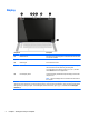
Display Component Description (1) WLAN antennas* Send and receive wireless signals to communicate with wireless local area networks (WLANs). (2) Internal microphones (2) Record sound. (3) Webcam light On: The webcam is in use. (4) Webcam Records video and captures photographs. Some models allow you to video conference and chat online using streaming video. To use the webcam, from the Start screen, type camera, and then select Camera from the list of applications.
Right side Component (1) Description Memory card reader Reads optional memory cards that store, manage, share, or access information. To insert a card: Hold the card label-side up, with connectors facing the slot, insert the card into the slot, and then press in on the card until it is firmly seated. To remove a card: Press in on the card it until it pops out.
Rear Component (1) Description Vents (2) Enable airflow to cool internal components. NOTE: The computer fan starts up automatically to cool internal components and prevent overheating. It is normal for the internal fan to cycle on and off during routine operation. (2) AC adapter light ● On: The AC adapter is connected and the battery is charged. ● Off: The computer is using battery power. (3) Power connector Connects an AC adapter. (4) USB 3.
Top Touchpad Component (1) Description Touchpad zone Reads your finger gestures to move the pointer or activate items on the screen. TIP: You can disable the touchpad or change the touchpad sensitivity and click speed. (2) Left touchpad button Functions like the left button on an external mouse. (3) Right touchpad button Functions like the right button on an external mouse.
Lights TIP: You can customize the keyboard lighting. Component (1) Power light ● On: The computer is on. ● Blinking: The computer is in the Sleep state, a powersaving state. The computer shuts off power to the display and other unneeded components. ● Off: The computer is off or in Hibernation. Hibernation is a power-saving state that uses the least amount of power. (2) Caps lock light On: Caps lock is on, which switches the keys to all capital letters.
Buttons and speakers Component (1) Description Power button ● When the computer is off, press the button to turn on the computer. ● When the computer is on, press the button briefly to initiate Sleep. ● When the computer is in the Sleep state, press the button briefly to exit Sleep. ● When the computer is in Hibernation, press the button briefly to exit Hibernation. CAUTION: Pressing and holding down the power button will result in the loss of unsaved information.
Keys TIP: You can customize these keys in HP OMEN Control. Component Description (1) Programmable gaming keys Allow you to create up to 30 different gaming key combinations when used alone or with the fn, ctrl, alt, or shift keys. (2) esc key Displays system information when pressed in combination with the fn key. (3) fn key Executes frequently used system functions when pressed in combination with one of the action keys or the esc key.
Labels The labels affixed to the computer provide information you may need when you troubleshoot system problems or travel internationally with the computer. IMPORTANT: All labels described in this section will be located in one of 3 places depending on your computer model: affixed to the bottom of the computer, located in the battery bay, or under the service door. TIP: You can also press fn+esc for system information. ● Service label—Provides important information to identify your computer.
3 Illustrated parts catalog NOTE: HP continually improves and changes product parts. For complete and current information on supported parts for your computer, go to http://partsurfer.hp.com, select your country or region, and then follow the on-screen instructions.
Item Component Spare part number (1) Display assembly: The display assembly is spared at the subcomponent level only. For more display assembly spare part information, see Display assembly subcomponents on page 15.
Item Component Spare part number Includes 8-GB of system memory and 4 GB of discrete graphics memory for use in models with Windows 8.1 Standard 788616-501 Includes 8-GB of system memory and 4 GB of discrete graphics memory for use in models with Windows 8.
Component Spare part number For use in South Korea 490371-AD1 For use in Switzerland 490371-111 For use in the United Kingdom and Singapore 490371-031 Display assembly subcomponents Item Component Spare part number (1) Display Panel Kit (includes bezel, touch glass, and panel) 788608-001 NOTE: Must be assembled in a clean room.
Sequential part number listing 16 Spare part number Description 490371-001 Power cord for use in North America (3-pin, black, 1.83-m) 490371-011 Power cord for use in Australia (3-pin, black, 1.83-m) 490371-021 Power cord for use in Europe (3-pin, black, 1.83-m) 490371-031 Power cord for use in the United Kingdom and Singapore (3-pin, black, 1.83-m) 490371-081 Power cord for use in Denmark (3-pin, black, 1.83-m) 490371-111 Power cord for use in Switzerland (3-pin, black, 1.
Spare part number Description 788603-161 Keyboard/top cover for use in Latin America (includes top cover, keyboard, keyboard support bracket, and screws) 788603-171 Keyboard/top cover for use in Saudi Arabia (includes top cover, keyboard, keyboard support bracket, and screws) 788603-251 Keyboard/top cover for use in Russia (includes top cover, keyboard, keyboard support bracket, and screws) 788603-291 Keyboard/top cover for use in Japan (includes top cover, keyboard, keyboard support bracket, and s
18 Spare part number Description 788615-001 System board equipped with an Intel Core I7-4710 processor; includes 16-GB of system memory and 4 GB of discrete graphics memory for use in models without the Windows operating system (includes thermal grease and thermal pads) 788615-501 System board equipped with an Intel Core I7-4710 processor; includes 16-GB of system memory and 4 GB of discrete graphics memory for use in models with Windows 8.
4 Removal and replacement preliminary requirements Tools required You will need the following tools to complete the removal and replacement procedures: ● Flat-bladed screw driver ● Magnetic screw driver ● Phillips P0 screw driver Service considerations The following sections include some of the considerations that you must keep in mind during disassembly and assembly procedures.
An electronic device exposed to ESD may not be affected at all and can work perfectly throughout a normal cycle. Or the device may function normally for a while, then degrade in the internal layers, reducing its life expectancy. CAUTION: To prevent damage to the computer when you are removing or installing internal components, observe these precautions: Keep components in their electrostatic-safe containers until you are ready to install them.
Workstation guidelines Follow these grounding workstation guidelines: ● Cover the workstation with approved static-shielding material. ● Use a wrist strap connected to a properly grounded work surface and use properly grounded tools and equipment. ● Use conductive field service tools, such as cutters, screw drivers, and vacuums. ● When fixtures must directly contact dissipative surfaces, use fixtures made only of staticsafe materials.
The following table lists the shielding protection provided by antistatic bags and floor mats.
5 Removal and replacement procedures for Authorized Service Provider parts Computer replacement procedures This chapter provides removal and replacement procedures for Authorized Service Provider only parts. CAUTION: This computer does not have user-replaceable parts. Only HP authorized service providers should perform the removal and replacement procedures described here. Accessing the internal part could damage the computer or void the warranty.
2. Pry up to remove the rubber strips from the bottom of the computer. NOTE: You cannot replace the removed rubber strips. You must use new rubber strips when reassembling the computer. All spare part kits that require removal of the bottom cover include replacement rubber strips. 24 3. Remove the 11 Phillips PM2.0×5.0 screws that secure the bottom cover to the computer. 4. Lift the bottom cover off the computer.
Disconnecting the battery IMPORTANT: Be sure to disconnect or remove the battery before removing any components from the computer. Before disconnecting the battery, follow these steps: 1. Turn off the computer. If you are unsure whether the computer is off or in Hibernation, turn the computer on, and then shut it down through the operating system. 2. Disconnect the power from the computer by unplugging the power cord from the computer. 3. Disconnect all external devices from the computer. 4.
WLAN module Component Spare part number Intel Wireless 7260BN 802.11 bgn 2x2 WiFi + BT 4.0 Combo Adapter 784640-006 Intel Dual Band Wireless-AC 7260(non v-Pro) 802.11 AC 2x2 WiFi + BT 4.0 Combo Adapter 784645-006 Before replacing the WLAN module, follow these steps: 1. Turn off the computer. If you are unsure whether the computer is off or in Hibernation, turn the computer on, and then shut it down through the operating system. 2.
Reverse this procedure to install the WLAN module.
Solid-state drive (M.2) Description Spare part number 128 GB solid-state drive (SSD), M.2.2280, TLC, SATA 788611-001 256 GB solid-state drive (SSD), M.2.2260, MLC, PCIe 788612-001 512 GB solid-state drive (SSD), M.2.2280, MLC, PCIe 788613-001 Before removing the solid-state drive, follow these steps: 1. Turn off the computer. If you are unsure whether the computer is off or in Hibernation, turn the computer on, and then shut it down through the operating system. 2.
Heat sink and fans NOTE: The heat sink and fans are spared together. Component Spare part number Heat sink and fans (includes replacement thermal material) 788600-001 Before replacing the heat sink and fans, follow these steps: 1. Turn off the computer. If you are unsure whether the computer is off or in Hibernation, turn the computer on, and then shut it down through the operating system. 2. Disconnect the power from the computer by unplugging the power cord from the computer. 3.
5. Use the following image to determine where thermal material must be installed on the heat sink and system board. (1)-(6) show locations on the system board that require thermal material. (7)-(12) show locations on the heat sink that require thermal material. Reverse this procedure to install the heat sink and fans.
Battery IMPORTANT: Be sure to disconnect or remove the battery before removing any components from the computer. Component Spare part number Battery, 4-cell, 58-Wh, 3.82-Ah, Li-ion 778978-006 Before replacing the battery, follow these steps: 1. Turn off the computer. If you are unsure whether the computer is off or in Hibernation, turn the computer on, and then shut it down through the operating system. 2. Disconnect the power from the computer by unplugging the power cord from the computer. 3.
3. Lift the battery (3) from the computer. Reverse this procedure to install the battery.
TouchPad Component Spare part number TouchPad (includes cable) 788607-001 Before replacing the TouchPad, follow these steps: 1. Turn off the computer. If you are unsure whether the computer is off or in Hibernation, turn the computer on, and then shut it down through the operating system. 2. Disconnect the power from the computer by unplugging the power cord from the computer. 3. Disconnect all external devices from the computer. 4. Remove the bottom cover (see Bottom cover on page 23). 5.
System board Component Spare part number System board equipped with an Intel Core i7-4710 processor (includes thermal grease and thermal pads) Includes 16 GB of system memory and 4 GB of discrete graphics memory for use in models without the Windows operating system 788615-001 Includes 16 GB of system memory and 4 GB of discrete graphics memory for use in models with Windows 8.1 Standard 788615-501 Includes 16 GB of system memory and 4 GB of discrete graphics memory for use in models with Windows 8.
(6): Keyboard cable (7): Touch control cable (8): Webcam cable (9): Right speaker cable (10): Right light assembly (11): Power button board cable (12): Light module cable 2. Remove the three Phillips PM2.0×3.0 screws (1) that secure the system board to the computer. 3. Remove the bolthead screw (2) that secures the system board to the computer.
4. Lift the system board (3) out of the computer. Reverse this procedure to install the system board.
Power button board Component Spare part number Power button board (includes cable) 788605-001 Before replacing the power button board, follow these steps: 1. Turn off the computer. If you are unsure whether the computer is off or in Hibernation, turn the computer on, and then shut it down through the operating system. 2. Disconnect the power from the computer by unplugging the power cord from the computer. 3. Disconnect all external devices from the computer. 4.
Power connector cable Component Spare part number Power connector cable (includes cable, bracket, and screws) 788599-001 Before replacing the power connector cable, follow these steps: 1. Turn off the computer. If you are unsure whether the computer is off or in Hibernation, turn the computer on, and then shut it down through the operating system. 2. Disconnect the power from the computer by unplugging the power cord from the computer. 3. Disconnect all external devices from the computer. 4.
Speakers Component Spare part number Speaker Kit (includes left and right speakers) 788610-001 Before replacing the speakers, follow these steps: 1. Turn off the computer. If you are unsure whether the computer is off or in Hibernation, turn the computer on, and then shut it down through the operating system. 2. Disconnect the power from the computer by unplugging the power cord from the computer. 3. Disconnect all external devices from the computer. 4.
Light modules Component Spare part number Light modules (includes left, right, and rear modules and cables) 788604-001 Light modules are located under each speaker and at left and right near the rear of the computer. The two modules at the rear are wired together and secured with screws. The left and right modules under the speakers are secured with adhesive. Before replacing the light modules, follow these steps: 1. Turn off the computer.
Reverse this procedure to install the light modules. Display assembly Before replacing the display assembly, follow these steps: 1. Turn off the computer. If you are unsure whether the computer is off or in Hibernation, turn the computer on, and then shut it down through the operating system. 2. Disconnect the power from the computer by unplugging the power cord from the computer. 3. Disconnect all external devices from the computer. 4. Remove the bottom cover (see Bottom cover on page 23). 5.
3. Separate the display assembly from the computer (2). 4. To separate the display from the display enclosure: a. Insert a plastic tool (1) in the slot between the display and the enclosure and slide around the entire display to disengage the display from the enclosure. CAUTION: Be sure to use a tool that will not damage the display.
b. Remove the display from the enclosure (2). The display enclosure is available using spare part number 788597-001. NOTE: The display enclosure spare part kit also includes the display hinge kit. The Display Panel Kit is available using spare part number 788608-001. NOTE: 5. The Display Panel Kit must be assembled in a clean room. To disconnect the display cable from the display panel: a. Rotate the display downward so it lays flat (1). b.
c. 6. 44 Remove the display cable, noting its routing path for reinstallation (4). To remove the touch control board from the top of the display: a. Disconnect the cables from the two connectors on the top of the board (1). b. Pry up on the touch control module to release the adhesive strip (2) that secures the module to the display, and the remove the module. c. Disconnect the cable from the module (3).
d. Note the cable routing path for reinstallation (4). The touch control board is available using spare part number 788606-001. 7. To replace the webcam module : a. Disconnect the cable from the webcam module (1). b. Use a tool to pry up on the webcam to release the adhesive strip (2) that secures the webcam module to the display.
c. Lift the webcam module from the display (3). The webcam is available using spare part number 788620-001. Reverse this procedure to reassemble and install the display assembly.
6 Specifications Computer specifications Dimensions Metric U.S. Width 382.9 mm 15.08 in Depth 247.5 mm 9.74 in Height - front 15.5 mm 0.61 in Height - rear 19.9 mm 0.78 in Weight 2.27 kg 5.
Solid-state drive specifications Dimensions 128 GB* 256 GB* 512 GB* Length 80 mm 60 mm 80 mm Width 22 mm 22 mm 22 mm Interface type SATA-3 PCIe PCIe Form factor M.2 2280 M.2 2260 M.
7 Using Setup Utility (BIOS) and HP PC Hardware Diagnostics (UEFI) Setup Utility, or Basic Input/Output System (BIOS), controls communication between all the input and output devices on the system (such as disk drives, display, keyboard, mouse, and printer). Setup Utility (BIOS) includes settings for the types of devices installed, the startup sequence of the computer, and the amount of system and extended memory.
Downloading a BIOS update CAUTION: To reduce the risk of damage to the computer or an unsuccessful installation, download and install a BIOS update only when the computer is connected to reliable external power using the AC adapter. Do not download or install a BIOS update while the computer is running on battery power, docked in an optional docking device, or connected to an optional power source.
To start HP PC Hardware Diagnostics UEFI: 1. Turn on or restart the computer, quickly press esc, and then press f2. The BIOS searches three places for the diagnostic tools, in the following order: a. Connected USB drive NOTE: To download the HP PC Hardware Diagnostics (UEFI) tool to a USB drive, see Downloading HP PC Hardware Diagnostics (UEFI) to a USB device on page 51. 2. b. Hard drive c.
8 Backing up, restoring, and recovering This chapter provides information about the following processes: ● Creating recovery media and backups ● Restoring and recovering your system Creating recovery media and backups 1. After you successfully set up the computer, create HP Recovery media. This step creates a backup of the HP Recovery partition on the computer. The backup can be used to reinstall the original operating system in cases where the hard drive is corrupted or has been replaced.
Worldwide Telephone Numbers booklet included with the computer. You can also find contact information from the HP website. Go to http://www.hp.com/support, select your country or region, and follow the on-screen instructions. If you use an external optical drive, it must be connected directly to a USB port on the computer; the drive cannot be connected to a USB port on an external device, such as a USB hub. ● Be sure that the computer is connected to AC power before you begin creating the recovery media.
Recovering using HP Recovery Manager HP Recovery Manager software allows you to recover the computer to its original factory state by using the HP Recovery media that you created or by using the HP Recovery partition (select models only). If you have not already created recovery media, see Creating HP Recovery media on page 52.
Using HP Recovery media to recover You can use HP Recovery media to recover the original system. This method can be used if your system does not have an HP Recovery partition or if the hard drive is not working properly. 1. If possible, back up all personal files. 2. Insert the HP Recovery media that you created, and then restart the computer. NOTE: If the computer does not automatically restart in HP Recovery Manager, change the computer boot order. See Changing the computer boot order on page 55. 3.
9 Power cord set requirements The wide-range input feature of the computer permits it to operate from any line voltage from 100 to 120 volts AC, or from 220 to 240 volts AC. The 3-conductor power cord set included with the computer meets the requirements for use in the country or region where the equipment is purchased. Power cord sets for use in other countries and regions must meet the requirements of the country or region where the computer is used.
Country/region Accredited agency Applicable note number South Korea EK 4 Sweden CEMKO 1 Switzerland SEV 1 Taiwan BSMI 4 The United Kingdom BSI 1 The United States UL 2 1. The flexible cord must be Type HO5VV-F, 3-conductor, 1.0-mm² conductor size. Power cord set fittings (appliance coupler and wall plug) must bear the certification mark of the agency responsible for evaluation in the country or region where it will be used. 2. The flexible cord must be Type SPT-3 or equivalent, No.
10 Recycling When a non-rechargeable or rechargeable battery has reached the end of its useful life, do not dispose of the battery in general household waste. Follow the local laws and regulations in your area for battery disposal. HP encourages customers to recycle used electronic hardware, HP original print cartridges, and rechargeable batteries. For more information about recycling programs, see the HP Web site at http://www.hp.com/ recycle.
Index A AC adapter 6 AC adapter, spare part number 14, 16 action keys identifying 10 audio, product description 1 audio-out (headphone)/audio-in (microphone) jack 6 B backups 52 base enclosure, spare part numbers 16 battery disconnecting 25 removal 31 spare part number 14, 16, 31 bezel spare part number 15 BIOS determining version 49 downloading an update 50 updating 49 Bluetooth label 11 boot order changing HP Recovery Manager 55 bottom 11 bottom cover removal 23 spare part number 23 buttons left touchpad
L labels Bluetooth 11 Microsoft Certificate of Authenticity 11 regulatory 11 serial number 11 service 11 wireless certification 11 WLAN 11 light modules removal 40 spare part number 13, 17, 40 lights AC adapter 6 caps lock 8 mute 8 power 8 wireless 8 M memory card reader, identifying 5 memory card, identifying 5 memory, product description 1 microphone, product description 1 Mini DisplayPort identifying 6 minimized image creating 54 minimized image recovery 54 model name 1 mute light, identifying 8 O operat
U USB 3.