HP P4459A 8-Port Fibre Loop Switch Installation & Operation Guide HP Part Number 5971-0861 Printed in February 2001
Notice The information contained in this document is subject to change without notice. Hewlett-Packard makes no warranty of any kind with regard to this material, including, but not limited to, the implied warranties of merchantability and fitness for a particular purpose. Hewlett-Packard shall not be liable for errors contained herein or for incidental or consequential damages in connection with the furnishing, performance, or use of this material.
HP P4459A 8-Port Fibre Loop Switch Installation & Operation Guide Safety Instructions The following sections describe the symbols used on the fibre loop switch and within this guide and also provides safety information about the product: • Symbols Used on Equipment • Symbols in Text • Grounding Requirements Symbols Used on Equipment The following table describes the symbols that are used on the fibre loop switch.
HP P4459A 8-Port Fibre Loop Switch Installation & Operation Guide Symbols in Text The following symbols are used in the following formats to highlight special messages throughout this guide: Note: This format is used to highlight information of importance or special interest. Caution: This format is used to highlight information that will help you prevent equipment failure or loss of data. Warning: This format is used to highlight material involving possibility of injury or equipment damage.
Contents Contents ..........................................................................................................................v Preface...........................................................................................................................vii Related Publications .............................................................................................. vii Related Web Sites ................................................................................................
HP P4459A 8-Port Fibre Loop Switch Installation & Operation Guide Appendix A: Fibre Loop Switch Functional Specifications ......................................37 Switching ...............................................................................................................37 Physical Specifications ..........................................................................................37 Environmental Specifications ..............................................................................
Preface The fibre loop switch provides an affordable entry-level SAN switch with multiple connectivity options. This guide provides information about the features and capabilities of the fibre loop switch, and how to install it. Related Publications The following publications provide information regarding Storage Area Networks (SANs) and the Fibre Channel protocol. Building Storage Networks, Farley, Marc, Osborne/McGraw-Hill, 2000. ISBN 0-07-212-050-9. Fibre Channel Arbitrated Loop, Kembel, Robert W.
HP P4459A 8-Port Fibre Loop Switch Installation & Operation Guide Related Web Sites These web sites, among others, provide significant information regarding SANs and the Fibre Channel protocol. Table 1: viii Related Websites Site URL ANSI http://www.ansi.org/docs/home.html Fibre Channel Industry Association http://www.fibrechannel.com/ Storage Network Industry Association http://www.snia.
Chapter 1 Introducing the HP P4459A 8-Port Fibre Loop Switch The following sections of this chapter provide an overview of the features and functions of the fibre loop switch: • Fibre Loop Switch Features • Switching Operation Fibre Loop Switch Features The fibre loop switch features an integral 12Gb/sec. engine that enables full duplex, concurrent switching on all ports.
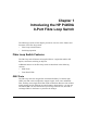
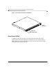
HP P4459A 8-Port Fibre Loop Switch Installation & Operation Guide Figure 1: Front View of the Fibre Loop Switch Power Connector GBIC Ports Switch Status LEDs Front Panel LEDs In addition to the port connectors, the front panel of the fibre loop switch contains LEDs that provide diagnostic information for both switch and port status, and an IEC power plug connector. Figure 2 shows the locations of the LEDs and the power plug connector.
Introducing the HP P4459A 8-Port Fibre Loop Switch Figure 2: Fibre Loop Switch front panel Power Plug Connector Switch Status LEDs Port Status LEDs Table 1 describes the operation of the switch LEDs and Table 2 describes the operation of the port LEDs on the front panel of the fibre loop switch. Table 1: Fibre Loop Switch LEDs Name Color Function fault Amber Indicates that the switch is running a self-test during start-up, or a failure occurred.
HP P4459A 8-Port Fibre Loop Switch Installation & Operation Guide Switching Operation The fibre loop switch implements the Fibre Channel Arbitrated Loop protocol. It provides concurrent connections to the storage area network (SAN) without changing the FC-AL interface, which most SAN end-node devices normally communicate. The SAN operation changes dramatically when comparing a switch with a hub environment.
Introducing the HP P4459A 8-Port Fibre Loop Switch wish to communicate. The addition of a hub, as shown in the center of the same figure, merely allows the cables from each node to go to a centralized location, such as a wiring closet where the hub is located. The media and bandwidth on that port are shared. The fibre loop switch has been designed with a non-blocking switch backplane; there is enough switch matrix bandwidth available to support simultaneous conversations between many nodes.
HP P4459A 8-Port Fibre Loop Switch Installation & Operation Guide • If node A is free, node C’s data is forwarded directly to node A without interference. That is, the messages do not circulate through each device on the loop and so latency savings on this transaction are also gained. Note that all transactions are directed between the two communicating nodes. No traffic ever circulates the entire network as it would in a loop topology.
Introducing the HP P4459A 8-Port Fibre Loop Switch that it is ready to participate by sending a LIP. Obviously, this interrupts any traffic in progress on that switch port, or on another switch port that is involved in a connection with a device on that switch port. However, it need not disrupt communications on any other switch port. Upon receiving a LIP, the switch conducts a series of passive tests on the new node, to verify that it is wellbehaved.
HP P4459A 8-Port Fibre Loop Switch Installation & Operation Guide 8
Chapter 2 Installing the Fibre Loop Switch The following sections of this chapter provide detailed instructions for installing a fibre loop switch: • Unpacking the Fibre Loop Switch • Installing and Removing GBICs in the Fibre Loop Switch • Rack Mounting the Fibre Loop Switch • Powering up a System • Cabling for the Fibre Loop Switch Note: Only trained personnel should install a loop switch. Please read all instructions fully before performing the installation.
HP P4459A 8-Port Fibre Loop Switch Installation & Operation Guide Installing and Removing GBICs in the Fibre Loop Switch Each port that you plan on using on the fibre loop switch must be configured with an HP-supported GBIC to provide media connectivity. Depending on the GBIC installed, connectivity options include copper and short-wave multi-mode fiber.
Installing the Fibre Loop Switch Figure 4: GBIC Orientation D-connector Guide tab Key Guide tab 3. Slide the GBIC through the port door and plug it into the 20-pin connector (not visible) on the host circuit board until it is firmly seated. If the GBIC does not install easily into the port, do not force it. Instead, try removing it and inverting the GBIC’s orientation. Warning: Do not look directly for the GBIC laser source. Laser beams can be harmful to your eyes. 4. 5.
HP P4459A 8-Port Fibre Loop Switch Installation & Operation Guide 2. Squeeze the latch levers (on the GBIC) together and pull the GBIC straight out. Note: GBIC latching mechanisms vary by manufacturer. Rack Mounting the Fibre Loop Switch The following sections provide information and procedures on how to rack mount the fibre loop switch. Warning: Reduce your risk of electric shock or damage to equipment by following these precautions: • Do not disable the power cord grounding plug.
Installing the Fibre Loop Switch Rack Installation Basics Caution: Do the following to prevent the rack enclosure from tipping over. Failure to take these precautions could result in serious injury and equipment damage. • Extend the anti-tip foot, or verify that the anti-tip feature is installed. • Verify that the leveler feet are lowered. • Do NOT extend more than one piece of equipment at a time out from the front of the rack.
HP P4459A 8-Port Fibre Loop Switch Installation & Operation Guide instructions that come with your rack or HP NetServer, or refer to the following web site: http://www.hp.com/racksolutions Note: The installation instructions that follow use “left” and “right” to refer to rack columns as viewed from the rear of the rack. Figure 5 and Figure 6 present a visual summary of the switch’s rack-mounting hardware.
Installing the Fibre Loop Switch Figure 6: Mounting in HP Rack System/E and HP Rack System/U Racks Right Front Rack Column Left Front Rack Column "L" Spacer "R" Spacer Sleeves Right Rear Rack Column Switch Left Rear Rack Column Rails Tools Required To install the switch in an HP rack, you need a T25 Torx driver and a #1 Phillipshead screwdriver.
HP P4459A 8-Port Fibre Loop Switch Installation & Operation Guide • Step 4: Attach the Sleeves to the Front Rack Columns • Step 5: Attach the Switch Rails to the Switch Chassis • Step 6: Install the Switch • Step 7: Complete the Installation Step 1: Preparation Before you install the switch into an HP rack, refer to the rack documentation as you extend the anti-tip foot or ensure that the anti-tip feature is installed. Lower the leveler feet.
Installing the Fibre Loop Switch Figure 7: Marking Holes and Attaching Barrel Nuts on HP Systems Racks Right Rear Rack Column EIA Unit Barrel Nuts Left Rear Rack Column 17
HP P4459A 8-Port Fibre Loop Switch Installation & Operation Guide Figure 8: Marking Holes and Attaching Barrel Nuts on HP Rack System/E and HP Rack System/U Racks Right Rear Rack Column EIA Unit Barrel Nuts Left Rear Rack Column Step 2: Mark the Rack Column Holes Use tape or a marking pen to mark the screw holes where you will install the barrel nuts: • On each rear rack column, mark the top and bottom holes of the EIA unit on the inside of the column, as shown in Figure 7 and Figure 8.
Installing the Fibre Loop Switch 2. Place two barrel nuts on each of the rear rack columns at the holes you marked, as shown in Figure 7 and Figure 8. Note: Install the barrel nuts with the threaded nut part of the barrel nut on the inside face of the rack column. 3. For HP Systems racks only, attach one barrel nut to each of the front rack columns at the holes you marked. For HP Rack System/E and HP Rack System/U racks do NOT attach barrel nuts to the front columns.
HP P4459A 8-Port Fibre Loop Switch Installation & Operation Guide Figure 9: Installing Spacers on HP Rack System/E and HP Rack System/U Racks Left Front Right Front Rack Column Rack Column "L" Spacer Right Rear Rack Column "R" Spacer Left Rear Rack Column Step 4: Attach the Sleeves to the Front Rack Columns When the installation is complete, each rack rail will consist of two parts, as shown in Figure 10 and Figure 11: • A switch rail, which is mounted on the switch chassis and is later attached to the
Installing the Fibre Loop Switch Figure 10: Identifying Switch Rails and Sleeves (Oriented for HP Racks) Switch Rail Sleeve Sleeve Flange Switch Rail Flange 2. Identify the six Torx screws.
HP P4459A 8-Port Fibre Loop Switch Installation & Operation Guide Figure 11: Attaching Sleeves to an HP Systems Rack Right Front Rack Column Rack Nut Rack Nut Sleeve Sleeve Sleeve Flanges Left Front Rack Column 22
Installing the Fibre Loop Switch Figure 12: Attaching Sleeves to HP Rack System/E and HP Rack System/U Racks Right Front Rack Column Spacers on Inside of Rack Columns Right Sleeve Sleeve Flanges Left Sleeve Left Front Rack Column 3. Position one sleeve on the inside of the rack front column with the sleeve’s flange side toward the rack column, as shown in Figure 11 or Figure 12.
HP P4459A 8-Port Fibre Loop Switch Installation & Operation Guide Step 5: Attach the Switch Rails to the Switch Chassis 1. Remove the two side screws (one on each side of the switch chassis) that retain the cover, as shown in Figure 13. You will not use these short screws in the rest of this assembly.
Installing the Fibre Loop Switch Step 6: Install the switch Have the remaining four Torx screws available as you install the switch. 1. 2. 3. 4. Pick up the switch chassis (with the switch rails installed) with the open switch rail ends away from you. Carry it to the rear of the rack. Carefully align the switch rail ends with the open rack sleeves, and gently ease the chassis into the rack sleeves like a drawer, as shown in Figure 14 and Figure 15.
HP P4459A 8-Port Fibre Loop Switch Installation & Operation Guide Figure 14: Installing the Switch into an HP Systems Rack Right Front Rack Column Sleeves Right Rear Rack Column Switch Left Front Rack Column Left Rear Rack Column 26 Switch Rail Flanges
Installing the Fibre Loop Switch Figure 15: Installing the Switch into an HP Rack System/E or HP Rack System/U Rack Right Front Rack Column Sleeves Right Rear Rack Column Switch Left Front Rack Column Left Rear Rack Column 5. 6. Switch Rail Flanges Attach the other switch rail to the other rear rack column in the same way. Use the T25 driver in a couple of passes to tighten all six screws that you installed in the rack columns. Step 7: Complete the Installation 1.
HP P4459A 8-Port Fibre Loop Switch Installation & Operation Guide Plugging in the other end of the power cord will apply power to the switch. You can do either of the following: • Connect the other end of the power cord to the power receptacle on the rack, which means you will hot-plug devices to the switch. 2. • Wait to plug in the other end of the power cord, so that you can connect devices to the switch before you power it.
Installing the Fibre Loop Switch Powering up a System When bringing up an FC-AL system, first make all the connections with the equipment powered down, then turn on the fibre loop switch before turning on any other operating component. The fibre loop switch does not have an On/Off switch. For convenience and safety, connect the power cord to a grounded AC outlet near the rack or desk so it is easily accessible. Ensure that the appropriate power plug is available for the installation area. 1.
HP P4459A 8-Port Fibre Loop Switch Installation & Operation Guide copper cabling. Table 3 provides the specifications for optical cable support and Table 4 provides the specifications for copper cable support. Table 3: Optical cable requirements for the Fibre Loop Switch Cable Spec Multi Mode Fiber Single Mode Fiber Distance in Meters 2m–300m 2m–500m 2m–10Km Fiber Core Size 62.5 µm (TIA standard for premise wiring for US and international use.) 50 µm (Not standard for premise wiring use.
Chapter 3 Fibre Loop Switch Troubleshooting The following sections of this chapter provide information to help you troubleshoot problems with your fibre loop switch: • General Maintenance Considerations • Troubleshooting the Switch • Reset Button • Connections • Temperature Control General Maintenance Considerations To protect the switch for longer use, we recommend that you: • Periodically vacuum the external surfaces of the switch to remove dust.
HP P4459A 8-Port Fibre Loop Switch Installation & Operation Guide • Never insert foreign objects into optical transmit and receive ports. • Do not bend fiber cable to less than a three-inch bend radius. Troubleshooting the Switch If there is a problem accessing a device connected to the fibre loop switch, the source of the problem can be with the device, the switch, the host, or any of the connections between the host and device. Follow the steps outlined below to investigate the problem.
Fibre Loop Switch Troubleshooting Table 5: Reading The Power, Fault, and Initialization LEDs Label LED Color/ Pattern Interpretation Possible Causes Power Green/ON The unit is connected to an AC power source and the internal power supply is functioning. This is the normal state when powered on. OFF No power within the switch. -The line has no voltage. -The switch is disconnected or the power cable is bad. -The switch is faulty. Fault Amber/ON -Switch is running a self-test.
HP P4459A 8-Port Fibre Loop Switch Installation & Operation Guide Link (Green Fault (Amber) Interpretation Possible Causes ON ON Switch is resetting. Not a valid state at any other time. Power up or a reset. Reset Button Use the reset button with caution. The Reset button on the front panel of the switch resets the internal control microprocessor of the switch. Sometimes a reset clears a problem that appears to be the result of an unidentified error.
Fibre Loop Switch Troubleshooting • Keep unused GBIC connectors covered with the plugs that are shipped with them to prevent contamination from obscuring or attenuating the light signals. Fibre Channel Cables The fibre loop switch uses Fibre Channel cables to communicate with cascaded and end-node devices. Loose or broken cables can cause a number of problems. Inspect the cabling between the switch and attached Fibre Channel devices. Check for loose, dirty, broken, or bent cabling and connectors. 1. 2.
HP P4459A 8-Port Fibre Loop Switch Installation & Operation Guide 36
Appendix A Fibre Loop Switch Functional Specifications Switching Switch Backplane Bandwidth..........12 Gigabits per second Switching Mode...............................Non-Blocking Port Speed........................................1.0625 Gigabits per second Communication Modes ...................Full or Half Duplex, Diplex Port-to-Port Latency ........................< 2 microseconds Physical Specifications Specifications that follow are without mounting hardware or GBICs. Height ........................
HP P4459A 8-Port Fibre Loop Switch Installation & Operation Guide Electrical Specifications AC Voltage ......................................100–240 VAC autosensing Frequency ........................................50 to 60 Hz Rated Input Current .........................1.5A — 0.7A LED Specifications Front Panel LED Indicators Power...............................................Green Fault.................................................Amber Init....................................................
Fibre Loop Switch Functional Specifications European Union (EU)......................EN 55022: 1994 +A1 +A2, Class A EN61000-3-2: 1995 EN61000-3-3: 1995 EN 55024: 1998 Japan ................................................VCCI V3: 1997, Class A JEIDA Guideline for the suppression of harmonics: 1993 Australia/New Zealand....................AS/NZS 3548/95, Class A Other Countries ...............................
HP P4459A 8-Port Fibre Loop Switch Installation & Operation Guide 40
Appendix B Regulatory Information Regulatory Notices Electromagnetic Compliance Electromagnetic Compatibility (EMC) requirements have been established in many countries to regulate the radio frequency energy generated by Information Technology Equipment (ITE). This energy is generated during the normal and intended use of this equipment and so it is limited by country regulations to levels intended to minimize potential interference to other electrical equipment, including public safety services.
HP P4459A 8-Port Fibre Loop Switch Installation & Operation Guide Notice for United States Class A Equipment This equipment has been tested and found to comply with the limits for Class A digital devices, pursuant to Part 15 of the FCC (Federal Communications Commission Rules). These limits are designed to provide reasonable protection against harmful interference when the equipment is operated in a commercial environment.
Regulatory Information Notice for Korea Class A Warning Please note that this equipment has been approved for business purposes with regards to electromagnetic interference, if purchased in error for use in residential area, you may wish to exchange the equipment where you purchased it.
HP P4459A 8-Port Fibre Loop Switch Installation & Operation Guide Notice for European Union Radio Frequency Emissions Warning for Accessories This product has been found to comply with CISPR 22 Class A EMC emission limits. Installation and use of a Class A accessory creates a system that meets the requirements for industrial and commercial environments. However, in a domestic environment, this product may cause radio interference, in which case the user may be required to take adequate measures.
Regulatory Information Declaration of Conformity (US and EU) DECLARATION OF CONFORMITY according to ISO/IEC Guide 22 and EN 45014 Manufacturer's/Supplier Name: Hewlett-Packard Company Manufacturer's/Supplier Address: 10955 Tantau Avenue Cupertino, Ca 95014 USA declares, that the product Product Name: Model Number(s): Product Options: HP 8-Port Fibre Loop Switch P4459A All conforms to the following Product Specifications: Safety: IEC 60950: 1991 +A1, A2, A3, A4/ EN 60950: 1992 + A1, A2, A3, A4, A11 G
HP P4459A 8-Port Fibre Loop Switch Installation & Operation Guide Regulatory Notices - Product Safety This product may be equipped with a Hewlett-Packard Optical GBIC containing a laser. In which case the GBIC is a Class 1 Laser Product per US/FDA/CDRH (21 CFR) and per IEC-825-1 (EN60825-1 and A11). Laser Safety– United States CAUTION This device contains a laser system and is classified as a "Class-1 Laser Product" under a U.S.
Regulatory Information Laser Safety - Germany VORSICHT Diese Gerät enthält ein Laser-System und ist als "LASER PRODUKT DER KLASSE 1"klassifiziert. Für den richtigen Gebrauch dieses Modells die Bedienungsanleitung sorgfältig durchlesen und als Referenz aufbewahren. Falls Probleme mit diesem Modell aufreten, die nächste "authorisierte Services-Verrtetung" benachrichtigen. Um einen direkten Kontakt mit dem Laserstrahl zu vermeiden, soll das Gehäuse nicht geöffnet werden.
HP P4459A 8-Port Fibre Loop Switch Installation & Operation Guide CLASS 1 LASER PRODUCT LASSER KLASSE 1 PRODUKT 48 This Fibre Loop Switch Unit is classified as a CLASS 1 LASER PRODUCT.
Appendix C Warranty and Support The hardware warranty below applies to components purchased as accessories. If your component was factory installed as part of an HP Netserver model, refer to the HP Netserver Warranty and Service/Support Booklet for the warranty limitations, customer responsibilities, and other terms and conditions.
HP P4459A 8-Port Fibre Loop Switch Installation & Operation Guide notice of such defects during the warranty period, HP or Reseller will either, at its option, repair or replace products that prove to be defective. Should HP or Reseller be unable to repair or replace the hardware accessory within a reasonable amount of time, Customer's alternate remedy shall be a refund of the purchase price upon return of the hardware accessory product.
Warranty and Support World Wide Web On the World Wide Web go to: http://netserver.hp.
HP P4459A 8-Port Fibre Loop Switch Installation & Operation Guide 52
Glossary This glossary contains terms and acronyms that may be found in this documentation. AL_PA Arbitrated Loop Physical Address. The low-order byte of a 3-byte Fibre Channel Source/Destination ID field that defines an address hierarchy. This is also called a Loop ID. See D_ID or S_ID. AL_PD A destination AL_PA. AL_PS A source AL_PA.
HP P4459A 8-Port Fibre Loop Switch Installation & Opeartion Guide Bandwidth The amount of data per second that can be transferred from one device to another. Bandwidth limits are set by a combination of speed of transfer, capacity of the pipe, number of pipes, and overhead of sending the data. It is possible to transmit one signal at the maximum specified bandwidth, or several different signals simultaneously on different channels, each of them using a portion of available bandwidth.
Glossary D_ID Destination ID. A Fibre Channel Address of a frame defining the destination node for that frame. Diplex Communications In addition to full duplex communications between a pair of nodes, a node can receive from another node, while simultaneously transmitting to a third node independently. Domain See Fibre Channel Address. Duplex (full) Operation of a data communication link where transmissions are possible in both directions simultaneously.
HP P4459A 8-Port Fibre Loop Switch Installation & Opeartion Guide FC-0 The set of Fibre Channel standards that address media (optics, copper, connectors), and physical signalling over that media (signal rates and timing, signal quality, power, jitter, etc.). FC-1 The set of Fibre Channel standards that address 8B/10B encoding/decoding and transmission protocol. FC-2 The set of Fibre Channel standards that address link protocols: framing, flow control, link services, and error recovery.
Glossary Fibre Channel (FC) An ANSI T11 standard which provides high-speed, high-reliability data transfers among computing devices, storage devices, and networked equipment. It defines a bi-directional, full-duplex serial data channel at speeds of 1 Gigabit per second and higher, over distances up to 30 km. Current implementations support the transport of SCSI and IP protocols over switched and loop network topologies.
HP P4459A 8-Port Fibre Loop Switch Installation & Opeartion Guide Full Duplex Communications A pair of nodes able to both simultaneously send and receive data between each other for an aggregate of 2 Gbps, effectively doubling the communications rate between the two nodes. Frame The smallest unit of information carrying user data and protected by Fibre Channel error control and recovery. Up to 2112 bytes per frame can be transported. GBIC Gigabit Interface Converter.
Glossary LILP Loop Initialization Loop Position map is the accumulation of all of the information reported in the LIRP frames. It is optionally sent out by the initialization master at the end of the initialization sequence. Link In this context, it is a pair of fibers (RX for inbound and TX for outbound) that carries information to and from a port. It is also called a channel. LIP Loop Initialization Primitive.
HP P4459A 8-Port Fibre Loop Switch Installation & Opeartion Guide L_Port Loop Port. It only has the capability to communicate over FC-AL hubs and through FL_Ports. LPSM Loop Port State Machine. It resides on each loop-capable port and is responsible for performing the loop protocols and the repeater function to pass information through. MAC Address Media Access Control address. It is the 48-bit (12 digit hexadecimal), IEEE 802.1, Universal LAN MAC address (ULA).
Glossary Network A collection of interconnected components and the protocols and physical methods those components use to communicate. Network components consist of network elements (infrastructure components) and network attachments (devices which use the network to communicate). A Storage Area Network is a network whose elements consist of computing devices, storage devices, and storage subsystems. The predominant SAN protocol used is currently Fibre Channel. NL_Port Node Loop Port.
HP P4459A 8-Port Fibre Loop Switch Installation & Opeartion Guide Out-of-band Using a separate channel for signaling to ensure full bandwidth availability for its primary purpose. For example, although more costly, it ensures full bandwidth availability for voice or critical data transmission. PLDA Private Loop Direct Attach. A profile that defines an interoperable FC-AL implementation. Port A hardware pathway into and out of a node that performs data communications over the FC link.
Glossary Router A device connected to two or more networks that decides to which network to send the data. It is often used in SANs to connect SCSI devices to Fibre Channel networks. SAN Storage Area Network. This concept brings networking to storage. It is a highly scalable, managed, server-storage infrastructure that offers gigabit speed data connectivity, high system availability, extensive fault tolerance, and low cost of ownership.
HP P4459A 8-Port Fibre Loop Switch Installation & Opeartion Guide Star A configuration of computing devices within a LAN where each user is connected by links radiating out from a central connection point such as a hub. Switch Port A port on a device that can directly connect two devices together through switch connection. The P4459A is such a switch. Topology The physical or logical layout of nodes on a network. WWN Worldwide Name. It defaults to the lowest value MAC Address assigned to any port.