HP 3 Phase UPS User Guide Abstract This document includes installation, configuration, and operation information for the HP 3 Phase UPS. This document is for the person who installs and maintains power products. HP assumes you are qualified in the servicing of high-voltage equipment and trained in recognizing hazards in products with hazardous energy levels.
© Copyright 2008, 2013 Hewlett-Packard Development Company, L.P. The information contained herein is subject to change without notice. The only warranties for HP products and services are set forth in the express warranty statements accompanying such products and services. Nothing herein should be construed as constituting an additional warranty. HP shall not be liable for technical or editorial errors or omissions contained herein.
Contents Component identification ............................................................................................................... 7 3 Phase UPS overview ............................................................................................................................... 7 UPS front panel ......................................................................................................................................... 8 UPS front panel controls ................................
Readying the equipment ................................................................................................................. 56 Installing the mounting rails ...................................................................................................................... 56 Preparing the rails for integrated shipping .................................................................................................. 58 Switching off the UPS battery circuit breaker ............................
Replacing the batteries ............................................................................................................................. 87 Important battery safety information ................................................................................................. 87 Battery care and storage guidelines ................................................................................................. 87 UPS battery replacement procedure ..................................................
Ordering spares .................................................................................................................................... 106 UPS spare parts list ................................................................................................................................ 106 Hardware options ................................................................................................................................. 106 Support and other resources .........................
Component identification 3 Phase UPS overview The HP 3 Phase UPS protects your sensitive electronic equipment from the most common power problems including power failures, power sags, power surges, brownouts, and line noise. Power outages can occur when you least expect it and power quality can be erratic. These power problems have the potential to corrupt critical data, destroy unsaved work sessions, and damage hardware - causing hours of lost productivity and expensive repairs.
The Power Bus Bar for parallel systems, mounted in the rear of an HP rack, provides the required input and output connections for the paralleled UPSs and has a single system-rated input connection. The parallel UPS system can be installed with Output Power Modules or connected to rack-mounted power distribution systems. Note these guidelines when configuring the UPS standalone unit or parallel system: • There is a maximum of four ERMs per UPS.
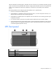
UPS front panel controls Item Description Function 1 Left arrow or ESC Cancel/return to the previous menu 2 Up arrow Scroll through the menu structure 3 Down arrow Scroll through the menu structure 4 Right arrow or enter Select an option UPS front panel LED indicators Item LED description 1 Power On 2 On Battery Component identification 9
Item LED description 3 Auto-bypass 4 Alarm For more information, see "LED and audible alarm troubleshooting (on page 94)" .
CAUTION: • Do not connect the REPO port to any utility connected circuits. Reinforced insulation to the utility is required. The REPO switch must have a minimum rating of 24 Vdc and 20 mA and be a dedicated latching-type switch for the 3 Phase UPS only, no other device or circuit including a single phase UPS. The REPO signal must remain active for at least 250 ms for proper operation.
ERM rear panel Item Description 1 Circuit breaker 2 ERM input connector (from another ERM output) 3 ERM output connector (to the UPS or another ERM) Component identification 12
UPS installation Precautions Save these instructions. This document contains important safety instructions that should be followed during installation, operation, and maintenance of the UPS and batteries. WARNING: A risk of personal injury from electric shock and hazardous energy levels exists. The installation of options and routine maintenance and service of this product must be performed by individuals who are knowledgeable about the procedures, precautions, and hazards associated with AC power products.
Selecting a site WARNING: To prevent fire or electric shock, install the unit in a temperature- and humidity-controlled indoor environment, free of conductive contaminants. When selecting a site, consider the following factors: • Elevated operating ambient temperature—If the equipment is installed in a closed or multi-unit rack assembly, the operating ambient temperature of the rack environment might be greater than room ambient temperature.
CAUTION: Always plan the rack installation so that the heaviest item is on the bottom of the rack. Install the heaviest item first, and continue to populate the rack from the bottom to the top. NOTE: Mounting hardware for square- and round-holed racks is included in the UPS kit. 1. Select the proper holes in the rack for positioning the UPS in the rack. The UPS rails are installed in positions 1 and 12. 2. Loosen the hex nuts, and extend the brackets to the desired length.
3. Insert screws through the rack into the mounting rail and the front of each mounting bracket. 4. Install cage nuts or clip nuts into the rear of the rack.
5. Insert screws through the mounting rail into the cage nuts or clip nuts. 6. Tighten the hex nuts. IMPORTANT: If preparing the rails for integrated shipping, install the rear mounting brackets. Installing the UPS Before installing the UPS, review and observe all warnings in "Precautions (on page 13)." WARNING: A risk of personal injury or damage to the equipment exists. Uneven loading of equipment in the rack might cause the rack to become unstable.
CAUTION: Always plan the rack installation so that the heaviest item is on the bottom of the rack. Install the heaviest item first, and continue to populate the rack from the bottom to the top. 1. Install the mounting rails ("Installing the mounting rails" on page 56, "Installing the mounting rails" on page 14). 2. With one person on each side of the carton, lift the chassis and lower it to the floor in front of the rack. 3. Install the mounting ears on the chassis using the screws provided. 4.
Removing the UPS battery bracket Be sure that all circuit breakers on the rear panel of the UPS are in the Off position. Installing the batteries WARNING: To prevent personal injury, prepare the area and observe all materials-handling procedures when transporting a battery module. Battery modules weigh 20 kg (44 lb).
Replacing the UPS battery bracket Attaching the UPS front bezel 1. Connect the cable to the electronics module. 2. Attach the UPS front bezel. Connecting the ground bonding cable The ground bonding screw is provided as an attachment point for conductors. Use a ground bonding cable if the rack contains any conductors for the purpose of functional grounding or bonding of ungrounded metal parts.
The ground bonding cable is not included. Connecting the REPO port This UPS has two REPO ports, normally-open and normally-closed. Before connecting to a REPO port, review and observe all warnings. WARNING: The pins on the REPO port are polarity sensitive. Be sure to verify polarity while connecting the REPO port in parallel with other HP UPSs.
NOTE: The REPO wiring of a standalone UPS can be connected with the REPO wiring of a parallel system if the same sense (NO or NC) contacts are used. Be sure to match the polarity for the contacts. 1. Verify that the UPS is powered down and all power sources are removed. For more information, see "Powering down the standalone UPS (on page 72)." 2. Mount the remote REPO switch. HP recommends mounting the REPO switch near the operator's consoles or near the exit doors.
1. Verify that the UPS is powered down and all power sources are removed. For more information, see "Powering down the standalone UPS (on page 72)." 2. Mount the remote REPO switch. HP recommends mounting the REPO switch near the operator's consoles or near the exit doors. For enclosure dimensions and wiring knockouts, see the REPO switch manufacturer's installation instructions. 3. Connect the appropriate external switch to terminal block 5, normally-closed REPO, and then discard the jumper wire.
Switching on the UPS battery circuit breaker When the UPS is plugged in and the battery circuit breaker is on, the UPS automatically enters Standby mode and begins charging the batteries. Connecting devices to the UPS CAUTION: Do not plug laser printers into the UPS output receptacles. The instantaneous current drawn by this type of printer can overload the UPS. Before connecting devices, verify that the UPS will not overload by checking that the ratings of the devices do not exceed the UPS capacity.
b. Plug the output module into the special UPS output receptacle, located on the rear of the UPS. Item Description 1 Rack corner post 2 Mounting locations 3 Mounting top bracket 4 Output cord 5 Mounting bottom bracket 6 Input cord Charging the UPS batteries With the UPS in Standby mode, allow the batteries to charge before putting the UPS into service. IMPORTANT: Charge the batteries for at least 48 hours before supplying backup power to devices.
5. If optional ERMs are installed, switch all ERM battery circuit breakers to the On position. Be sure that the "Batteries Disconnected" alarm has cleared. Be sure that no other alarms appear on the UPS front panel display. If the Alarm LED is flashing, do not proceed until all alarms clear. Check the UPS status from the front panel to view the active alarms. Correct the alarms and restart if necessary. 6. Press any button once and then press the left arrow button to select the TURN UPS ON/OFF menu. 7.
Bottom entry 1. Remove the UPS above the wireway. See "Replacing the UPS (on page 89)" . 2. Remove the eight screws on the wireway top cover and retain. 3. Slide the cover back and off the wireway and retain. 4. Remove the six screws on the conduit landing plate and retain. 5. Remove the plate and retain. 6. Use a Greenlee punch to provide one or more holes in the conduit landing plate to accommodate the input and output wiring from the utility to the Power Bus Bar. 7.
Top entry Use a Greenlee punch to provide one or more holes in the top of the wireway. Install one or more holes in the center rear of the top of the racks. NOTE: Top entry wiring does not interfere with access areas for the fans, connectors, breakers or X-Slot cards on any HP 3 Phase UPS. See the wireway label. Wiring the terminal block Connect the input, output and ground wires to the Power Bus Bar terminal block. Route the three input phases and the input neutral through the ferrite assembly.
Power Bus Bar terminal block Terminal position Power Bus Bar wire function Terminal wire size rating* Tightening torque Output 1 Phase 1 out 31.1 Nm (275 lb in) 2 Phase 2 out 3 Phase 3 out 4 Phase 1 in 5 Phase 2 in 6 Phase 3 in 7 Neutral 8 Neutral 9 Neutral 10 Ground 13.3 mm2 (6 AWG) to 177 mm2 (350 kcmil) 13.3 mm2 (6 AWG) to 177 mm2 (350 kcmil) 13.3 mm2 (6 AWG) to 177 mm2 (350 kcmil) 13.3 mm2 (6 AWG) to 177 mm2 (350 kcmil) 13.3 mm2 (6 AWG) to 177 mm2 (350 kcmil) 13.
The ground bonding cable is not included. Connecting the REPO port This UPS has two REPO ports, normally-open and normally-closed. Before connecting to a REPO port, review and observe all warnings. WARNING: The pins on the REPO port are polarity sensitive. Be sure to verify polarity while connecting the REPO port in parallel with other HP UPSs.
You can install an optional REPO circuit that shuts down the entire parallel system using a single switch. To install a REPO switch for a parallel system, the selected REPO command (NO or NC) contacts from each UPS in the system must be in parallel. To install a REPO switch for a parallel system: 1. Verify that the UPS system is powered down and all power sources are removed. For more information, see "Powering down the parallel system (on page 73)." 2. Mount the remote REPO switch.
3. Connect the appropriate external switch to terminal block 4, normally-open REPO. Connect Pin 1 to Pin 1 and connect Pin 2 to Pin 2 of each UPS. IMPORTANT: Always test the REPO function before applying the critical load to avoid accidental load loss. For more information, see "Verifying the REPO port connection (on page 71).
4. Reconnect terminal block 4, normally-open REPO, and then power on the UPS manually to restart. The pins should remain open to keep the UPS running. 5. Verify that the jumper is inserted in terminal block 5. Connecting to a normally-closed contact IMPORTANT: The remote switch must be in the closed position to enable power to the UPS output. You can install an optional REPO circuit that shuts down the entire parallel system using a single switch.
3. Connect the appropriate external switch to terminal block 5, normally-closed REPO. Connect Pin 1 to Pin 1 and connect Pin 2 to Pin 2 of each UPS, and then discard the jumper from terminal block 5. IMPORTANT: Always test the REPO function before applying the critical load to avoid accidental load loss. For more information, see "Verifying the REPO port connection (on page 71).
4. Reconnect terminal block 5, normally-closed REPO, and then power on the UPS manually to restart. Short the pins to keep the UPS running. Maximum resistance is 10 ohm. Connecting the UPSs to the Bus Bar To connect the parallel input cord from each paralleled UPS to the Bus Bar in the rack: 1. Gently loop and twist the parallel input cords to minimize stress on the cords. The loop and twist for each cord might vary depending on configuration and strain relief. 2.
4. Secure the parallel input cord by pushing in the cord retention bracket (3).
Switching on the UPS input circuit breaker 1. Switch the UPS input circuit breaker on each UPS to the On position. 2. Wait for the front panel display on each UPS to illuminate. The Alarm LED flashes on each UPS. 3. Check each UPS front panel display for active alarms or notices (other than "Batteries Disconnected"). Resolve any active alarms before continuing. For alarm troubleshooting, see "LED and audible alarm troubleshooting (on page 94).
Connecting devices to the UPS CAUTION: Do not plug laser printers into the UPS output receptacles. The instantaneous current drawn by this type of printer can overload the UPS. Before connecting devices, verify that the UPS will not overload by checking that the ratings of the devices do not exceed the UPS capacity. If the equipment rating is listed in amps, multiply the number of amps by the nominal AC source to determine the VA.
Powering up the parallel system NOTE: Be sure that the total equipment ratings do not exceed the UPS capacity to prevent an overload alarm. 1. Be sure that the "Batteries Disconnected" alarm has cleared. Be sure that no other alarms appear on the UPS front panel display. If the Alarm LED is flashing, do not proceed until all alarms clear. Check the UPS status from the front panel to view the active alarms. Correct the alarms and restart if necessary. 2.
WARNING: A risk of personal injury or damage to the equipment exists. Uneven loading of equipment in the rack might cause the rack to become unstable. Install the heavier components first, and then continue to populate the rack from the bottom to the top. CAUTION: Always plan the rack installation so that the heaviest item is on the bottom of the rack. Install the heaviest item first, and continue to populate the rack from the bottom to the top. 1.
Configuring the Parallel UPS Card 1. Unpack the Parallel UPS Card, and be sure that the card was not damaged during shipment. NOTE: If installing another X-Slot card, be sure to install the Parallel UPS Card in X-Slot Communication Bay 2. 2. Remove the UPS X-Slot communication bay cover, and retain the screws. 3. Set the jumper pins on the Parallel UPS Card according to the parallel configuration. For three or more paralleled UPSs: o Set the cards of the first and last UPS to Pins 1 and 2.
When powering up the UPS, the parallel system identifies the UPS wired after UNIT 1 as UNIT 2, and so on.
Item Description 12 UPS UNIT 3 8. Install the redundant signal wiring between the For Parallel Use Only and Standalone/Parallel terminals on each UPS. Remove the existing terminal block connectors before installing the cable. 9. Secure the cable to the UPS using cable ties and plastic standoffs. Be sure to check for correct polarity when installing the cable. CAUTION: If polarity or wiring is not correct, the parallel system does not operate normally.
Replacing the UPS battery bracket Attaching the UPS front bezel 1. Connect the cable to the electronics module.
2. Attach the UPS front bezel. Connecting the ground bonding cable The ground bonding screw is provided as an attachment point for conductors. Use a ground bonding cable if the rack contains any conductors for the purpose of functional grounding or bonding of ungrounded metal parts. The ground bonding cable is not included. Connecting the REPO port This UPS has two REPO ports, normally-open and normally-closed. Before connecting to a REPO port, review and observe all warnings.
WARNING: To meet the requirements stated in NEC (NFPA 70) Articles 645-10 and 645-11, a UPS installed in a computer equipment room must be connected to a REPO circuit. NOTE: Wire the connector block using stranded, nonshielded wire (AWG #22 - #18, or equivalent). HP recommends using different colors for the positive and negative wires. To avoid inadvertant EPO: • Minimize wire strain while connecting the REPO port. • Avoid allowing the wires to hang in the rear of the UPS.
3. Connect the appropriate external switch to terminal block 4, normally-open REPO. Connect Pin 1 to Pin 1 and connect Pin 2 to Pin 2 of each UPS. IMPORTANT: Always test the REPO function before applying the critical load to avoid accidental load loss. For more information, see "Verifying the REPO port connection (on page 71).
4. Reconnect terminal block 4, normally-open REPO, and then power on the UPS manually to restart. The pins should remain open to keep the UPS running. 5. Verify that the jumper is inserted in terminal block 5. Connecting to a normally-closed contact IMPORTANT: The remote switch must be in the closed position to enable power to the UPS output. You can install an optional REPO circuit that shuts down the entire parallel system using a single switch.
3. Connect the appropriate external switch to terminal block 5, normally-closed REPO. Connect Pin 1 to Pin 1 and connect Pin 2 to Pin 2 of each UPS, and then discard the jumper from terminal block 5. IMPORTANT: Always test the REPO function before applying the critical load to avoid accidental load loss. For more information, see "Verifying the REPO port connection (on page 71).
4. Reconnect terminal block 5, normally-closed REPO, and then power on the UPS manually to restart. Short the pins to keep the UPS running. Maximum resistance is 10 ohm. Connecting the UPSs to the Bus Bar To connect the parallel input cord from each paralleled UPS to the Bus Bar in the rack: 1. Gently loop and twist the parallel input cords to minimize stress on the cords. The loop and twist for each cord might vary depending on configuration and strain relief. 2.
4. Secure the parallel input cord by pushing in the cord retention bracket (3). Connecting the UPS to utility power WARNING: To prevent injury from electric shock or damage to the equipment: • Plug the input line cord into a grounded (earthed) electrical outlet that is installed near the equipment and is easily accessible. • Do not disable the grounding plug on the input line cord. The grounding plug is an important safety feature. • Do not use extension cords.
Switching on the UPS input circuit breaker 1. Switch the UPS input circuit breaker on each UPS to the On position. 2. Wait for the front panel display on each UPS to illuminate. The Alarm LED flashes on each UPS. 3. Check each UPS front panel display for active alarms or notices (other than "Batteries Disconnected"). Resolve any active alarms before continuing. For alarm troubleshooting, see "LED and audible alarm troubleshooting (on page 94).
CAUTION: Do not plug laser printers into the UPS output receptacles. The instantaneous current drawn by this type of printer can overload the UPS. Before connecting devices, verify that the UPS will not overload by checking that the ratings of the devices do not exceed the UPS capacity. If the equipment rating is listed in amps, multiply the number of amps by the nominal AC source to determine the VA.
NOTE: Be sure that the total equipment ratings do not exceed the UPS capacity to prevent an overload alarm. 1. Be sure that the "Batteries Disconnected" alarm has cleared. Be sure that no other alarms appear on the UPS front panel display. If the Alarm LED is flashing, do not proceed until all alarms clear. Check the UPS status from the front panel to view the active alarms. Correct the alarms and restart if necessary. 2.
ERM installation Preparing to install the hardware Before installing the hardware: 1. Be sure the necessary tools and materials (on page 13) are available. 2. Select an installation site ("Selecting a site" on page 14). 3. Prepare the equipment ("Readying the equipment" on page 14) for installation in the rack. Tools and materials The following tools are required for installation: • Phillips screwdriver • 10-mm hex-nut wrench • T-25 Torx driver A cage nut-fitting tool is supplied with the rack.
Readying the equipment 1. Check the battery recharge date specified on the label that is affixed to the shipping carton. IMPORTANT: Do not use the battery if the recharge date has passed. If the date on the battery recharge date label has passed without the battery being recharged, contact an HP authorized service representative for directions. 2. Transport the packaged unit to its installation location. 3. Unpack the equipment near the rack where the unit will be assembled.
2. Insert screws through the rack into the mounting rail and the front of each mounting bracket. 3. Install cage nuts or clip nuts into the rear of the rack.
4. Insert screws through the mounting rail into the cage nuts or clip nuts. 5. Tighten the wing nuts or hex nuts. Preparing the rails for integrated shipping If the unit is to be shipped in a rack: 1. Remove the hex nuts from the mounting rail. 2. Install the rail reinforcement plates and tighten using the hex nuts with captive washers, included in the kit, instead of the nuts included with the rail.
3. Install the rear mounting brackets using hex nuts. Wait until the unit is installed and the brackets are adjusted before tightening the nuts. Switching off the UPS battery circuit breaker WARNING: To prevent the UPS from dropping the load, be sure to switch off only the UPS battery circuit breaker. Once the battery circuit breaker is switched off, an audible alarm sounds, the Alarm LED flashes, and the LCD displays, "Battery not connected.
WARNING: To prevent personal injury from electric shock or damage to the equipment, verify that the circuit breaker is in the Off position. Installing the ERM Before installing the ERM, review and observe all warnings in "Precautions (on page 13)." WARNING: A risk of personal injury or damage to the equipment exists. Uneven loading of equipment in the rack might cause the rack to become unstable. Install the heavier components first, and then continue to populate the rack from the bottom to the top.
3. Install the mounting ears on the chassis using the screws provided. 4. With one person on each side, lift the chassis to rail level and slide the chassis on the mounting rails. 5. Attach the chassis to the rack using the supplied screws. 6. If using the rear mounting brackets, be sure that the bracket tabs are fully inserted into the rear panel cutouts, then tighten the brackets. The UPS auto-detects ERM installation by updating the system runtime.
Attaching the ERM front bezel Connecting the ERM to the UPS NOTE: To install a second ERM, plug the cable from the second ERM into the socket at the rear of the first ERM. Up to four ERM units can be connected.
Switching on the ERM circuit breaker Switching on the UPS battery circuit breaker When the UPS is plugged in and the battery circuit breaker is on, the UPS automatically enters Standby mode and begins charging the batteries. Charging the ERM batteries Connect the UPS to a grounded utility power outlet. When the UPS is plugged in, it automatically enters Standby mode and begins charging the ERM batteries.
UPS operations Mimic screen The Mimic screen shows the internal components of the UPS and a real-time display of the operating status. A thicker bar indicates that the node is energized. Modes of operation The UPS has four modes of operation: • Standby mode (on page 64) • Normal mode (on page 65) • Battery mode (on page 66) • Auto-Bypass mode (on page 66) Standby mode In Standby mode: • No power is available at the UPS output receptacles. • The UPS charges the batteries as necessary.
2. o Standalone UPS configuration—See "Powering down the standalone UPS (on page 72)." o Individual UPS in a parallel configuration—See "Powering down an individual paralleled UPS (on page 72)." o Parallel UPS configuration—See "Powering down the parallel system (on page 73)." Power to the load ceases. IMPORTANT: While in Standby mode, the UPS maintains the charge on the batteries, but no power is available at the output receptacles.
Transferring the UPS between Normal modes To transfer between Normal mode and Full-Time Standard mode: 1. Press any button to activate the menu options. 2. Select SETTINGS, USER SETTINGS, POWER STRATEGY, STANDARD, and ENTER to confirm. To transfer between Standard mode and Normal mode: 1. Press any button to activate the menu options. 2. Select SETTINGS, USER SETTINGS, POWER STRATEGY, HIGH EFFICIENCY, and ENTER to confirm.
9. Press any button to activate the menu options. 10. Select CONTROL, GO TO BYPASS MODE. The Auto-Bypass and Power On LEDs illuminated solid, indicating the UPS is operating in Auto-Bypass mode. The load is now powered by utility power. 11. Switch the load connector circuit breaker to the On position. 12. Press ESC until the HP logo appears. Transferring the UPS between modes To transfer between Normal mode and Auto-Bypass mode: 1. Press any button to activate the menu options. 2.
NOTE: Menu functions related to parallel systems appear only on paralleled UPSs.
Description Available settings Default setting Relay Config Relay: [Alarm-1][X-Slot 1-1/2/3/4] or [X-Slot 2-1/2/3/4] Alarm 1: empty X-Slots (1 or 2) Setup: [On Battery][Summary Alarm][On Bypass][UPS OK][custom][empty] #1: #2: #3: #4: Signal Inputs Serial Port Config UPS OK On Bypass Summary Alarm On Battery [empty][Logic] For more information, see "Programmable signal inputs (on page 77).
Description Available settings Default setting Site Wiring Fault Notice [Enabled][Disabled] Enabled Reset Custom Event Settings 0 through 32 Total: 0/32 REPO Configuration [Enabled][Disabled] Enabled Delay Setting the Battery Low alarm level The default Battery Low alarm level setting provides approximately 2.5 minutes of battery warning for a UPS. Additional ERMs installed in a parallel system can provide a longer warning time. To set the Battery Low Alarm Level: 1.
Running automatic battery tests Battery tests rely on backfeeding the utility, using the utility as a load. Some sites might choose to disable battery testing if their source is not capable of being backfed. Examples of such sources include generators, other UPSs, and other stiff or soft sources. If a source is not capable of being backfed, the UPS aborts the test (due to utility failure) and maintains the load and log the event.
CAUTION: If the polarity is reversed while connecting the REPO port, the UPS powers up normally. 2. 3. Power up the UPS. o Standalone UPS configuration—See "Powering up the standalone UPS (on page 25)." o Parallel UPS configuration—See "Powering up the parallel system (on page 39)." Verify proper connection of the REPO port: a. Disconnect the REPO port. b. Reconnect the REPO port. If the polarity is correct, the REPO connectors can be disconnected, and then reconnected, without initiating a REPO. c.
NOTE: If there is only one circuit breaker for all UPSs, do not switch off utility power until all UPSs are powered down. 9. Disconnect the UPS from utility power. If you are shutting down all the UPSs in a parallel system , repeat steps 1 through 7 for each UPS, then disconnect from utility power. Powering down the parallel system 1. Switch one UPS load connector circuit breaker to the Off position. 2. Press any button on the front panel display to activate the menu options. 3.
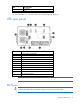
Communication Installing communication options and control terminals Item Description 1 Signal input 1 2 Signal input 2 3 Standalone/parallel 4 REPO (normally open) 5 REPO (normally closed) 6 DB-9 communication port 7 Redundant signal wiring (for parallel use only) 8 Relay output contacts 9 Option card bay 1 10 Option card bay 2 To install the communication options and control terminals: 1. Install the appropriate option card and/or necessary cable(s). 2.
o Standalone UPS configuration—See "Powering up the standalone UPS (on page 25)." o Parallel UPS configuration—See "Powering up the parallel system (on page 39)." Communication options The UPS has serial communication capabilities through the DB-9 communication port or through an X-Slot card in one of the available bays. The UPS supports two serial communication devices. NOTE: Relay, signal inputs, and the serial port baud rates are configurable through the front panel menus.
Pin number Signal name Function Direction from the UPS 4 — No connection — 5 GND Signal common (tied to chassis) — 6 — No connection — 7 — No connection — 8 — No connection — 9 — No connection — Control terminals The cables should be connected to the control terminal with a mating connector. Input and output terminals have a functional isolation from terminal to terminal. They are connected to the UPS chassis through individual 1 MW resistors.
The UPS incorporates a programmable relay output with potential free contacts for remote alarm indications. An additional four relay outputs can be obtained with the compatible Relay Interface option card. Programmable signal inputs The UPS incorporates two programmable signal inputs. HP recommends using non-polar (relay) control input. The pins must be shorted with maximum resistance of 10 ohm in order to activate the specific input. Verify control terminal connections if polarity control is required.
Mode transfers • If one UPS in a parallel system transfers from High Efficiency mode (on page 65) to Normal mode (on page 65), the other UPSs transfer also. • If one UPS transfers to Battery mode (on page 66), the remaining UPSs in the parallel system stay online. The transferred UPS might transfer back to online at any time, and the parallel system resynchronizes.
Metering The Output and Load Receptacle meter readings differ between a parallel system and a standalone UPS. In a parallel system, one UPS reads the Load Receptacle value for the total system (the others read zero), but each UPS displays its own Output value. For example, in a two-unit parallel system with one Anderson load connection for 12 kVA, the Load Receptacle current would read 12 kVA on one UPS and zero on the other UPS, but the Output measurement would be 6 kVA on each UPS (half the total).
Power management HP UPS Power Protection Agent overview The HP UPS Power Protection Agent runs on a local or network server and allows the management module to gracefully shut down the operating system of that server and optionally run a script during power failure. Install the agent on any machine that is powered by the UPS and any machine that the management module uses to initiate a command.
Maintenance Removing the UPS front bezel Removing the ERM front bezel Replacing the UPS electronics module Maintenance 81
NOTE: Do not disconnect the electronics module while the UPS is in Battery mode. This component is hot-swappable and can be replaced without powering down the UPS. However, Battery mode is not available and the load is not protected. 1. 2. (optional) To replace the component with the UPS powered down, do one of the following: o Standalone UPS configuration—See "Powering down the standalone UPS (on page 72).
7. Replace the screw. 8. If the configuration is parallel, reconnect the redundant signal cables. 9. Replace the front bezel. 10. Transfer the UPS to Normal mode (on page 65). Replacing UPS X-Slot cards This component is hot-swappable and can be replaced without powering down the UPS. 1. 2. (optional) To replace the component with the UPS powered down, do one of the following: o Standalone UPS configuration—See "Powering down the standalone UPS (on page 72).
3. Remove the two screws securing the X-Slot Card and slide the card out. To replace the component, reverse the removal procedure. NOTE: Replacing the HP Management Module might require power management software to be restarted or reconfigured. Configuring the Parallel UPS Card 1. Unpack the Parallel UPS Card, and be sure that the card was not damaged during shipment. NOTE: If installing another X-Slot card, be sure to install the Parallel UPS Card in X-Slot Communication Bay 2. 2.
o Set the card for the middle UPS(s) to Pins 2 and 3. 4. Install the Parallel UPS Card into an open X-Slot on the rear of the UPS. 5. Repeat steps 1 through 4 to install a Parallel UPS Card into each UPS to be paralleled. The HP 3 Phase UPS parallel system automatically assigns identities to each UPS in the system based on the order in which their Parallel UPS Cards are wired. For more information, see "Auto-identification (on page 78)" . 6.
When powering up the UPS, the parallel system identifies the UPS wired after UNIT 1 as UNIT 2, and so on.
Item Description 12 UPS UNIT 3 8. Install the redundant signal wiring between the For Parallel Use Only and Standalone/Parallel terminals on each UPS. Remove the existing terminal block connectors before installing the cable. 9. Secure the cable to the UPS using cable ties and plastic standoffs. Be sure to check for correct polarity when installing the cable. CAUTION: If polarity or wiring is not correct, the parallel system does not operate normally.
• Keep the area around the UPS clean and dust-free. If the environment is very dusty, clean the outside of the UPS regularly with a vacuum cleaner. • Maintain the ambient temperature at 25°C (77°F). • If storing a UPS for an extended period, recharge the batteries every 6 months: CAUTION: Because of the short shelf life of the batteries, avoid storing a battery spare as a backup.
4. Remove the UPS battery modules. To replace the component, reverse the removal procedure. IMPORTANT: Charge the batteries for at least 48 hours before supplying backup power to devices. The batteries charge to: • 80 percent of their capacity within 5 hours • 100 percent of their capacity within 48 hours Testing the new battery module NOTE: The batteries must be fully charged and the UPS must not be in Battery mode to perform the battery test.
2. Power down the UPS. o Standalone UPS configuration—See "Powering down the standalone UPS (on page 72)." o Individual UPS in a parallel configuration—See "Powering down an individual paralleled UPS (on page 72)." o Parallel UPS configuration—See "Powering down the parallel system (on page 73)." 3. Switch the circuit breaker for any attached ERMs to the Off (down) position ("Switching off the ERM circuit breaker" on page 59). 4.
2. Unplug the ERM from the back of the UPS. 3. Unplug the ERM from a second connected ERM. 4. Remove the front bezel on the ERM that is being replaced. 5. Remove the screws securing the ERM to the rack. 6. Remove the ERM from the rack. To replace the component, reverse the removal procedure. Updating the UPS firmware To update the UPS firmware, see the HP website (http://www.hp.com/go/rackandpower).
7. Click the Port Settings tab. The Port Settings screen appears. 8. Click Restore Defaults. The following default settings appear: o Bits per second: 9600 o Data Bits: 8 o Parity: None o Stop bits: 1 o Flow control: None 9. Click Advanced. The Advanced Settings screen appears. 10. From the COM Port Number drop down menu, select Com 1 for the USB port number, and then click OK.
a. Click Action. The Action Menu appears. b. Click Scan for hardware changes to refresh the screen and display the changes.
Troubleshooting LED and audible alarm troubleshooting This UPS is designed for durable, automatic operation and also alerts you whenever potential operating problems might occur. Usually the alarms shown on the control panel do not mean that the output power is affected. Instead, they are preventive alarms intended to alert you of a possible condition. The following table describes typical alarms and conditions.
On On—1 beep Overload every 3 seconds ("Overload condition" on page 98) On On—1 beep Overtemperature every 3 seconds ("Overtemperature condition" on page 98) On On—1 beep Site Wiring Fault every 3 seconds ("Site wiring condition" on page 99) For the location of individual LEDs, see "UPS front panel LED indicators (on page 9)." Silencing an audible alarm To silence an alarm, press any button on the front panel display to silence the alarm.
Action: 1. Be sure that the UPS battery circuit breaker is in the On position. 2. If the condition persists, contact an HP authorized service representative. Battery connection condition Possible cause: • The UPS does not recognize the internal batteries. • Two or more battery trays are disconnected. Action: 1. Be sure that all the battery trays are fully seated and locked in place. 2. If the condition persists, contact an HP authorized service representative.
1. Verify the bypass utility. 2. Check for one of the following alarms: o Bypass over or under voltage o Bypass over or under frequency o Bypass unavailable Check Parallel Board condition Possible cause: The UPS does not recognize another paralleled UPS. Action: 1. From the UPS Status menu, select the Units on Parallel Card option and be sure that all UPSs appear in the list. 2. If any UPS is missing, verify the Parallel UPS Card connections and recheck the status from the UPS front panel.
4. To supply power to the connected equipment, power up the UPS. o Standalone UPS configuration—See "Powering up the standalone UPS (on page 25)." o Parallel UPS configuration—See "Powering up the parallel system (on page 39)." Protected equipment is not on Possible cause: The UPS is operating normally, but some or all of the protected equipment is not on. Action: • Be sure that the equipment is plugged into the UPS receptacles. • Be sure that the output circuit breaker is in the Off position.
Remove one or more load devices to reduce the power requirements. Selective trip Possible cause: The UPS detected an internal fault. Action: If the condition persists, contact an HP authorized service representative. Site wiring condition Action: Contact a qualified electrician to be sure that: • The line and neutral wires are not reversed in the wall outlet. • A ground wire connection does not exist.
o 6. Parallel UPS configuration—See "Powering up the parallel system (on page 39)." Contact a qualified electrician to check the power cord connections. UPS does not provide the expected backup time Action: 1. Be sure that the battery circuit breakers are in the On position. 2. Allow the UPS batteries to charge for 48 hours. 3. If the condition persists, contact an HP authorized service representative. UPS does not transfer to Auto-Bypass mode Action: • Verify the bypass utility.
Specifications Model list Model Power levels (rated at nominal inputs) 12kVA NA UPS 12kVA or 12kW at 208 V* 8kVA NA UPS 8kVA or 8kW at 208 V* 12kVA INTL UPS 12kVA or 12kW at 400 V* 8kVA INTL UPS 8k VA or 8W at 400 V* ERM Up to 4 per UPS Power Bus Bar For up to 6 UPSs *Derated for line cord and nominal line voltage. UPS physical specifications Parameter Value Height 26.1 cm (10.3 in), 6U Depth 66 cm (26 in) Width 44.1 cm (17.
Cord model number Description Input plug type Length 12kVA Parallel NA 12 kW UL parallel Anderson 0.5 m (1.5 ft) 12kVA INTL 12 kW CE input IEC 309-32 A 3.7 m (12 ft) 8kVA INTL 12 kW CE input/output IEC 309-16 A 3.7/1.2 m (12/4 ft) 12kVA Parallel INTL 12 kW CE parallel 0.5 m (1.5 ft) Anderson Power Bus Bar and Wireway specifications Power Bus Bar Wireway Dimensions (WxDxH) 14.0 x 11.3 x 182.7 cm (5.5 x 4.4 x 71.
UPS output specifications 3 Phase UPS NA 3 Phase UPS INTL Nominal output voltage 120/208 Vac three-phase 230/400 Vac three-phase Output voltage variation (standard) 108-132 Vac phase to neutral 187-255 Vac phase to neutral 187-229 Vac phase to phase 324-441 Vac phase to phase 108-132 Vac phase to neutral 207-253 Vac phase to neutral 187-229 Vac phase to phase 358-438 Vac phase to phase Output receptacles on standalone UPSs—12kVA models Output module (2x L15-30R) Output module (2x IEC 309-16
Feature Specification Relative humidity Operating: 5% to 95%; noncondensing Non-operating: 5% to 95%; 38.7°C (101.
Battery runtimes are listed in minutes at 100% load. Model UPS internal batteries +1 ERM +2 ERMs +3 ERMs +4 ERMs 8kVA NA and INTL 9 22 32 43 55 12kVA NA and INTL 5 12 20 27 34 REPO port specifications The REPO port meets the requirements of NFPA Articles 645-10 and 645-11 for a Disconnecting Means.
Spares Ordering spares To order a spare, visit the HP website (http://www.hp.com/buy/parts). To replace parts under warranty, contact an HP authorized service representative.
Support and other resources Before you contact HP Be sure to have the following information available before you call HP: • Active Health System log (HP ProLiant Gen8 or later products) Download and have available an Active Health System log for 3 days before the failure was detected. For more information, see the HP iLO 4 User Guide or HP Intelligent Provisioning User Guide on the HP website (http://www.hp.com/go/ilo/docs).
Regulatory information Safety and regulatory compliance For safety, environmental, and regulatory information, see Safety and Compliance Information for Server, Storage, Power, Networking, and Rack Products, available at the HP website (http://www.hp.com/support/Safety-Compliance-EnterpriseProducts). Turkey RoHS material content declaration Ukraine RoHS material content declaration Warranty information HP ProLiant and X86 Servers and Options (http://www.hp.
• The UPS is plugged into a suitably grounded and wired outlet using no extension cords, adapters, other ground wires, or other electrical connections. • The UPS installation complies with all applicable electrical and safety codes specified by the NEC. • The UPS is used under normal operating conditions and users comply with all instructions and labels. • The UPS is not damaged by accident (other than a utility power transient), misuse, or abuse.
Electrostatic discharge Preventing electrostatic discharge To prevent damaging the system, be aware of the precautions you need to follow when setting up the system or handling parts. A discharge of static electricity from a finger or other conductor may damage system boards or other static-sensitive devices. This type of damage may reduce the life expectancy of the device. To prevent electrostatic damage: • Avoid hand contact by transporting and storing products in static-safe containers.
Acronyms and abbreviations ATS automatic transfer switch ERM extended runtime module IEC International Electrotechnical Commission PDU power distribution unit REPO remote emergency power off UPS uninterruptible power system Acronyms and abbreviations 111
Documentation feedback HP is committed to providing documentation that meets your needs. To help us improve the documentation, send any errors, suggestions, or comments to Documentation Feedback (mailto:docsfeedback@hp.com). Include the document title and part number, version number, or the URL when submitting your feedback.
Index A alarm cannot be silenced 94 alarm conditions 94 alarms, setting 70 alarms, silencing 71 alarms, troubleshooting 94 authorized reseller 107 Auto-Bypass LED, location 9 Auto-Bypass LED, troubleshooting 94 Auto-Bypass mode 66 B backup time, insufficient 100 batteries, care and storage 87 batteries, charging 25, 63 batteries, replacing 87, 88 batteries, specifications 104 battery bracket 19, 20 battery circuit breaker 24 battery circuit breaker, troubleshooting 95 Battery Low Alarm level, setting 70 Ba
G N General Alarm LED, location 9 General Alarm LED, troubleshooting 94 ground bonding cable, connecting 20 grounding methods 110 nominal voltage, configuring 67 Normal mode 65 H On Battery LED, location 9 On Battery LED, troubleshooting 94 operations, UPS 64 option card, replacing 83 optional items 106 ordering spares 106 output specifications 103 output voltage, troubleshooting 95 output wiring, installing 26 overload condition 98 overview, REPO port 10 overview, UPS 7 hardware options 106 hardware,
redundant signal wiring 78 regulatory compliance notices 108 relay output contacts 76 replacing the batteries 87, 88 replacing the electronics module 81 replacing the ERM 90 replacing the option card 83 REPO port, connecting 21, 22, 30, 33 REPO port, overview 10 REPO port, specifications 105 REPO port, verifying connection 71 REPO, normally-closed 22, 33 REPO, normally-open 21, 30 required tools 13 running battery tests 71 UPS firmware, updating 91 UPS operations 64 UPS, installing 17, 26, 39 UPS, replacin