HP Pavilion x360 Convertible PC Maintenance and Service Guide IMPORTANT! This document is intended for HP authorized service providers only.
© Copyright 2014 Hewlett-Packard Development Company, L.P. Bluetooth is a trademark owned by its proprietor and used by Hewlett-Packard Company under license. Intel and Core are U.S. registered trademarks of Intel Corporation. Microsoft and Windowsare U.S. registered trademarks of Microsoft Corporation. SD Logo is a trademark of its proprietor. The information contained herein is subject to change without notice.
Safety warning notice WARNING! To reduce the possibility of heat-related injuries or of overheating the device, do not place the device directly on your lap or obstruct the device air vents. Use the device only on a hard, flat surface. Do not allow another hard surface, such as an adjoining optional printer, or a soft surface, such as pillows or rugs or clothing, to block airflow. Also, do not allow the AC adapter to contact the skin or a soft surface, such as pillows or rugs or clothing, during operation.
iv Safety warning notice
Table of contents 1 Product description ........................................................................................................... 1 2 External component identification ..................................................................................... 6 Display ................................................................................................................................... 6 Buttons and speakers ..........................................................................
Keyboard/top cover ............................................................................................................... 34 TouchPad .............................................................................................................................. 37 Battery .................................................................................................................................. 38 Hard drive ......................................................................................
10 Recycling ...................................................................................................................... 75 Index .................................................................................................................................
viii
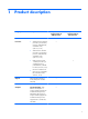
1 Product description Category Description Product Name Processor Chipset Computer models equipped with an AMD processor Computer models equipped with an Intel processor HP Pavilion x360 Convertible PC × × ● AMD® A8-6410 2.00-GHz (SC turbo up to 2.40-GHz) processor (1600-MHz FSB, 2.00-MB L2 cache, quad core, 15 W) × ● AMD A6-6310 1.80-GHz (SC turbo up to 2.40-GHz) processor (1600-MHz FSB, 2.00-MB L2 cache, quad core, 15 W) ● Intel® Core® i5-4210U 1.70-GHz (SC turbo up to 2.
Category Description Graphics (continued) Internal Graphics: Intel HD Graphics 4400 Computer models equipped with an AMD processor Computer models equipped with an Intel processor × Support for DX11, HD decode, and HDMI Panel 13.3-in (1368×768), AntiGlare, high-definition (HD), light-emitting diode (LED), low-voltage differntial-signalling (LVDS), WUXGA, TouchScreen with flush glass and MultiTouch enabled; 16:9 ultra-wide aspect ratio; typical brightness: 200 nits; ultraslim (2.
Category Description Hard drive Support for 6.35-cm (2.5-in) hard drives in 7.2-mm (.28-in) and 7.0-mm (.28-in) thicknesses Computer models equipped with an AMD processor Computer models equipped with an Intel processor × × Support for Accelerometer hard drive protection Support for the following single hard drive configurations: ● 1-TB, 5400-rpm, 7.2-mm ● 750-GB, 5400-rpm, 7.2-mm ● 500-GB, 5400-rpm, 7.0-mm Support for 500-GB, 5400-rpm, 7.
Category Description Computer models equipped with an AMD processor Computer models equipped with an Intel processor Ethernet Integrated 10/100 network interface card (NIC) × × Wireless Integrated wireless local area network (WLAN) options by way of wireless module × × × × × × One built-in WLAN antenna (in display assembly) Support for the following WLAN modules: 4 ● Intel Dual Band Wireless-AC 3160 802.11ac 1×1 WiFi + BT 4.0 Combo Adapter ● Qualcomm Atheros AR9565 802.
Category Description Keyboard/pointing devices Full-size, textured, chiclet-style keyboard, Computer models equipped with an AMD processor Computer models equipped with an Intel processor × × × × × × Touchpad requirements: Power requirements ● Clickpad with image sensor ● Taps enabled as default ● Multi-touch gestures enabled ● Ability to turn on and off ● Support for Microsoft® Windows® 8.
2 External component identification Display 6 Item Component Description (1) WLAN antennas (2)* Send and receive wireless signals to communicate with WLANs. (2) Internal microphones (2) Record sound. (3) Webcam light On: The webcam is in use. (4) Webcam Records video and captures photographs. Some models allow you to video conference and chat online using streaming video. To use the webcam, from the Start screen, type camera, and then select Camera from the list of applications.
Item Component Description (5) Windows button Returns you to the Start screen from an open app or the Windows desktop. NOTE: Pressing the Windows button again will return you to the previous screen. *The antennas are not visible from the outside of the computer. For optimal transmission, keep the areas immediately around the antennas free from obstructions. For wireless regulatory notices, see the section of the Regulatory, Safety, and Environmental Notices that applies to your country or region.
Buttons and speakers Item Component Description (1) Power button ● When the computer is off, press the button to turn on the computer. ● When the computer is on, press the button briefly to initiate Sleep. ● When the computer is in the Sleep state, press the button briefly to exit Sleep. ● When the computer is in Hibernation, press the button briefly to exit Hibernation. CAUTION: Pressing and holding down the power button will result in the loss of unsaved information.
Keys Item Component Description (1) esc key Displays system information when pressed in combination with the fn key. (2) fn key Executes frequently used system functions when pressed in combination with the b key or the esc key. (3) Windows key Returns you to the Start screen from an open app or the Windows desktop. NOTE: Pressing the Windows key again will return you to the previous screen. (4) Action keys Execute frequently used system functions.
Lights 10 Item Component Description (1) Power light ● On: The computer is on. ● Blinking: The computer is in the Sleep state, a powersaving state. The computer shuts off power to the display and other unneeded components. ● Off: The computer is off or in Hibernation. Hibernation is a power-saving state that uses the least amount of power. (2) Caps lock light On: Caps lock is on, which switches the keys to all capital letters. (3) Mute light ● Amber: Computer sound is off.
TouchPad Item Component Description (1) TouchPad zone Reads your finger gestures to move the pointer or activate items on the screen. NOTE: The TouchPad also supports edge-swipe gestures. (2) Left TouchPad button Functions like the left button on an external mouse. (3) Right TouchPad button Functions like the right button on an external mouse.
Left side Item Component Description (1) Power button ● When the computer is off, press the button to turn on the computer. ● When the computer is on, press the button briefly to initiate Sleep. ● When the computer is in the Sleep state, press the button briefly to exit Sleep. ● When the computer is in Hibernation, press the button briefly to exit Hibernation. CAUTION: Pressing and holding down the power button will result in the loss of unsaved information.
Item Component Description (4) Audio-out (headphone)/Audio-in (microphone) jack Connects optional powered stereo speakers, headphones, earbuds, a headset, or a television audio cable. Also connects an optional headset microphone. This jack does not support optional microphone-only devices. WARNING! To reduce the risk of personal injury, adjust the volume before putting on headphones, earbuds, or a headset. For additional safety information, refer to the Regulatory, Safety, and Environmental Notices.
Right side Item Component Description (1) Hard drive light ● Blinking white: The hard drive is being accessed. ● Amber: HP 3D DriveGuard has temporarily parked the hard drive. (2) Memory card reader Reads optional memory cards that store, manage, share, or access information. To insert a card: Hold the card label-side up, with connectors facing the slot, insert the card into the slot, and then push in on the card until it is firmly seated.
Bottom Item Component Description (1) Vents (2) Enable airflow to cool internal components. NOTE: The computer fan starts up automatically to cool internal components and prevent overheating. It is normal for the internal fan to cycle on and off during routine operation. (2) Speakers (2) Produce sound.
3 Illustrated parts catalog NOTE: HP continually improves and changes product parts. For complete and current information on supported parts for your computer, go to http://partsurfer.hp.com, select your country or region, and then follow the on-screen instructions. Locating the serial number, product number, and model number The product name (1), serial number (2), product number (3), warranty information (4), and model name (5) are located on the bottom of the computer.
Computer major components Computer major components 17
Item Component (1) Display assembly: The display assembly is spared at the subcomponent level only. For more display assembly spare part information, see Display assembly components on page 21.
Item (6) Component Spare part number Equipped with an AMD A8-6410 2.00-GHz (SC turbo up to 2.40-GHz) processor (1600-MHz FSB, 2.00-MB L2 cache, quad core, 15 W) and the Windows 8 Standard operating system 769075-501 Equipped with an AMD A8-6410 2.00-GHz (SC turbo up to 2.40-GHz) processor (1600-MHz FSB, 2.00-MB L2 cache, quad core, 15 W) and a non-Windows 8 Standard operating system 769075-001 Equipped with an AMD A6-6310 1.80-GHz (SC turbo up to 2.40-GHz) processor (1600-MHz FSB, 2.
Item Component Spare part number 750-GB, 5400-rpm 752099-005 500-GB, 5400-rpm 683802-006 500-GB, 5400-rpm, Hybrid 8-GB 732000-005 (12) Power connector cable 768012-001 (13) Speakers (includes left and right speakers and cables) 768024-001 (14) Power button board (includes cable) 768009-001 (15) Bottom cover: For use only on computer models equipped with an AMD processor: In natural silver finish for use in Europe, the Middle East, and Africa 784138-001 In natural silver finish for use i
Item Component Spare part number For use only on computer models in natural silver finish 768019-001 For use only on computer models in vibrant red finish 768018-001 Display assembly components Item Description Spare part number (1) Display bezel screw covers: The display bezel screw covers are included in the Rubber Kits, spare part numbers 768019-001 (for use only on computer models in natural silver finish) and 768018-001 (for use only on computer models in vibrant red finish).
Item Description Spare part number (6) Display Hinge Kit (includes left and right display hinges) 768036-001 (7) Display hinge covers (includes left and right display hinge covers): (8) In natural silver finish 768038-001 In vibrant red finish 768037-001 Display back cover In natural silver finish 768030-001 In vibrant red finish 768029-001 Miscellaneous parts Component Spare part number AC adapter: 65-W HP Smart adapter (non-PFC, EM, 3-wire, 4.
Component Spare part number For use in the People's Republic of China 755530-AA1 For use in South Africa 755530-AR1 For use in South Korea 755530-AD1 For use in Taiwan 755530-AB1 For use in Thailand 755530-201 Rubber Kit (includes bottom cover screw covers, computer feet, and display bezel screw covers) For use only on computer models in natural silver finish 768019-001 For use only on computer models in vibrant red finish 768018-001 Screw Kit 768041-001 Sequential part number listing Spar
Spare part number Description 752099-005 750-GB, 5400-rpm, SATA, 7.0-mm hard drive (does not include hard drive bracket or hard drive connector adapter) NOTE: The hard drive bracket and hard drive connector adapter are included in the Hard Drive Hardware Kit, spare part number 768020-001. 755530-001 Power cord for use on all computer models in North America (3-pin, black, 1.00-m) 755530-011 Power cord for use only on computer models equipped with an Intel processor in Australia (3-pin, black, 1.
Spare part number Description 767820-501 System board equipped with an Intel Core i5-4210U 1.70-GHz (SC turbo up to 2.70-GHz) processor (1600-MHz FSB, 3.00-MB L3 cache, dual core, 15 W), a graphics subsystem with UMA memory, and the Windows 8 Standard operating system (includes replacement thermal material) 767822-001 System board equipped with an Intel Core i3-4030U 1.90-GHz processor (1600-MHz FSB, 3.
26 Spare part number Description 767823-B31 Keyboard/top cover with metallic finish for use on all computer models in the Netherlands (includes keyboard cable) 767823-BA1 Keyboard/top cover with metallic finish for use only on computer models equipped with an Intel processor in Slovenia (includes keyboard cable) 767823-BB1 Keyboard/top cover with metallic finish for use only on computer models equipped with an Intel processor in Israel (includes keyboard cable) 767823-BG1 Keyboard/top cover with m
Spare part number Description 768040-001 Webcam/microphone module (includes double-sided adhesive) 768041-001 Screw Kit 768042-001 13.3-in, AG, HD, WLED, TouchScreen display panel (includes display bezel) 769075-001 System board equipped with an AMD A8-6410 2.00-GHz (SC turbo up to 2.40-GHz) processor (1600-MHz FSB, 2.
28 Spare part number Description 785448-001 Bottom cover in vibrant red finish for use only on computer models equipped with an Intel Dual Band Wireless-AC 3160 802.11ac 1×1 WiFi + BT 4.0 Combo Adapter in Europe, the Middle East, and Africa 785449-001 Bottom cover in natural silver finish for use only on computer models equipped with an Intel Dual Band Wireless-AC 3160 802.11ac 1×1 WiFi + BT 4.
4 Removal and replacement preliminary requirements Tools required You will need the following tools to complete the removal and replacement procedures: ● Flat-bladed screw driver ● Magnetic screw driver ● Phillips P0 screw driver Service considerations The following sections include some of the considerations that you must keep in mind during disassembly and assembly procedures.
Grounding guidelines Electrostatic discharge damage Electronic components are sensitive to electrostatic discharge (ESD). Circuitry design and structure determine the degree of sensitivity. Networks built into many integrated circuits provide some protection, but in many cases, ESD contains enough power to alter device parameters or melt silicon junctions. A discharge of static electricity from a finger or other conductor can destroy static-sensitive devices or microcircuitry.
Packaging and transporting guidelines Follow these grounding guidelines when packaging and transporting equipment: ● To avoid hand contact, transport products in static-safe tubes, bags, or boxes. ● Protect ESD-sensitive parts and assemblies with conductive or approved containers or packaging. ● Keep ESD-sensitive parts in their containers until the parts arrive at static-free workstations. ● Place items on a grounded surface before removing items from their containers.
Equipment guidelines Grounding equipment must include either a wrist strap or a foot strap at a grounded workstation. ● When seated, wear a wrist strap connected to a grounded system. Wrist straps are flexible straps with a minimum of one megohm ±10% resistance in the ground cords. To provide proper ground, wear a strap snugly against the skin at all times. On grounded mats with banana-plug connectors, use alligator clips to connect a wrist strap.
5 Removal and replacement procedures NOTE: This chapter provides removal and replacement procedures for Authorized Service Provider only components. Components described in this chapter should only be accessed by an authorized service provider. Accessing these components can damage the computer or void the warranty. There are as many as 52 screws that must be removed, replaced, and/or loosened when servicing the computer. Make special note of each screw size and location during removal and replacement.
Keyboard/top cover For use in country or region Spare part number For use in country or region Spare part number For use on all computer models: For use in Canada 767823-DB1 For use in the Netherlands 767823-B31 For use in the Czech Republic and Slovakia 767823-FL1 For use in Russia 767823-251 For use in Denmark, Finland, and Norway 767823-DH1 For use in Spain 767823-071 For use in France 767823-051 For use in Switzerland 767823-BG1 For use in Germany 767823-041 For use in the United K
4. Remove the three screw covers (2). The computer rear feet and the screw covers are included in the Rubber Kit, spare part number 768044-001. 5. Remove the 13 Phillips PM2.4×5.7 screws that secure the keyboard/top cover to the bottom cover. 6. Turn the computer right side up, with the front toward you.
7. Open the computer. CAUTION: Do not completely separate the keyboard/top cover from the bottom cover in the next step. There are 2 ribbon cables connecting the keyboard/top cover to the system board that can be damaged if too much separation is achieved. 8. Lift the front edge (1) of the keyboard/top cover until it (2) separates from the bottom cover. 9.
TouchPad NOTE: The TouchPad spare part kit includes the TouchPad cable. Description Spare part number For use only on computer models equipped with an AMD processor 774393-001 For use only on computer models equipped with an Intel processor 783028-001 Before removing the TouchPad, follow these steps: 1. Turn off the computer. If you are unsure whether the computer is off or in Hibernation, turn the computer on, and then shut it down through the operating system. 2.
3. Remove the TouchPad and cable (3) by releasing them from the top surface of the keyboard/ top cover. 4. Remove the TouchPad. Reverse this procedure to install the TouchPad. Battery Description Spare part number Battery, 3-cell, 43-WHr, 2.83-AHr, Li-ion (includes cable) 761230-005 Before removing the battery, follow these steps: 1. Shut down the computer. If you are unsure whether the computer is off or in Hibernation, turn the computer on, and then shut it down through the operating system. 2.
3. Detach the audio/USB board cable (3) from the battery. (The audio/USB board cable is attached to the battery with double-sided adhesive.) 4. Remove the two PM2.4×5.7 screws (4) that secure the battery to the bottom cover. 5. Lift the right side of the battery (5) until it rests at an angle. 6. Remove the battery (6) by sliding it up and to the right. Reverse this procedure to install the battery.
3. Disconnect the power from the computer by first unplugging the power cord from the AC outlet and then unplugging the AC adapter from the computer. 4. Remove the keyboard/top cover (see Keyboard/top cover on page 34). 5. Disconnect the battery cable from the system board (see Battery on page 38). Remove the hard drive: 40 1. Release the ZIF connector (1) to which the hard drive cable is attached, and then disconnect the hard drive cable from the system board. 2. Remove the two PM2.4×3.
5. If it is necessary to replace the hard drive connector adapter, slide the adapter (3) off of the front end of the hard drive. Reverse this procedure to reassemble and install the hard drive. WLAN module Description Spare part number Qualcomm Atheros AR9565 802.11b/g/n 1×1 WiFi + BT 4.0 Combo Adapter for use on all computer models 733476-005 Intel Dual Band Wireless-AC 3160 802.11ac 1×1 WiFi + BT 4.
3. Disconnect the power from the computer by first unplugging the power cord from the AC outlet and then unplugging the AC adapter from the computer. 4. Remove the keyboard/top cover (see Keyboard/top cover on page 34). 5. Disconnect the battery cable from the system board (see Battery on page 38). Remove the WLAN module: 1. Disconnect the WLAN antenna cables (1) from the terminals on the WLAN module. NOTE: The WLAN antenna cable labeled “1” connects to the WLAN module “Main” terminal labeled “1”.
Reverse this procedure to install the WLAN module. Audio/USB board Description Spare part number Audio/USB board (includes audio jack, cable, and USB port) 768011-001 Before removing the audio/USB board, follow these steps: 1. Shut down the computer. If you are unsure whether the computer is off or in Hibernation, turn the computer on, and then shut it down through the operating system. 2. Disconnect all external devices connected to the computer. 3.
6. Remove the audio/USB board (6) by sliding it up and to the right at an angle. Reverse this procedure to install the audio/USB board. Fan Description Spare part number Fan (includes cable) 768021-001 NOTE: To properly ventilate the computer, allow at least 7.6 cm (3 in) of clearance on the left side of the computer. The computer uses an electric fan for ventilation. The fan is controlled by a temperature sensor and is designed to turn on automatically when high temperature conditions exist.
Remove the fan: 1. Disconnect the fan cable (1) from the system board. 2. Remove the two Phillips PM2.4×5.7 screws (2) that secure the fan to the bottom cover. 3. Remove the fan (3). Reverse this procedure to install the fan. Speakers Description Spare part number Speakers (include left and right speakers and cables) 768024-001 Before removing the speakers, follow these steps: 1. Shut down the computer.
Remove the speakers: 1. Remove the two Phillips PM2.4×3.7 screws (1) that secure the speakers to the bottom cover. 2. Release the speakers cables from the retention clips (2) built into the bottom cover. 3. Remove the speakers (3). Reverse this procedure to install the speakers. Power button board Description Spare part number Power button board (includes cable) 768009-001 Before removing the power button board, follow these steps: 46 1. Shut down the computer.
Remove the power button board: 1. Release the ZIF connector (1) to which the power button board cable is attached, and then disconnect the power button board cable from the system board. 2. Remove the Phillips PM2.4×3.7 screw (2) that secures the power button board to the bottom cover. 3. Remove the power button board (3) and cable. Reverse this procedure to install the power button board. Display assembly NOTE: The display assembly is spared at the subcomponent level only.
Remove the display assembly: 1. Release the ZIF connector (1) to which the display panel cable is attached, and then disconnect the display panel cable from the system board. 2. Disconnect the WLAN antenna cables (2) from the terminals on the WLAN module. NOTE: The WLAN antenna cable labeled “1” connects to the WLAN module “Main” terminal labeled “1”. The WLAN antenna cable labeled “2” connects to the WLAN module “Aux” terminal labeled “2”. 48 3.
6. Remove the display assembly (3). 7. If it is necessary to replace the display panel or any of the display assembly internal components: a. Remove the display bezel screw covers (1). The screw covers are included in the Rubber Kits, spare part numbers 768019-001 (for use only on computer models in natural silver finish) and 768018-001 (for use only on computer models in vibrant red finish).
b. 50 Remove the two Phillips PM1.9×3.0 screws (2) that secure the display panel to the display assembly. 8. Release the top edge of the display panel (1) by pulling it away from the back cover. 9. Release the display panel cable (2) from the left display hinge.
10. Release the display TouchScreen cable (3) from the right display hinge. 11. Remove the display panel. The display panel is available using spare part number 768042-001. 12. If it is necessary to replace the webcam/microphone module: CAUTION: Before turning the display panel upside down, make sure the work surface is clear of tools, screws, and any other foreign objects. Failure to follow this caution can result in damage to the display panel. a.
c. Disconnect the webcam/microphone module cable (2) from the webcam/ microphone module. d. Remove the webcam/microphone module. The webcam/microphone module is available using spare part number 768040-001. 13. If it is necessary to replace the display panel cable: CAUTION: Before turning the display panel upside down, make sure the work surface is clear of tools, screws, and any other foreign objects. Failure to follow this caution can result in damage to the display panel. 52 a.
e. Remove the display panel cable (4). The display panel cable is available using spare part number 768031-001. 14. If it is necessary to replace the display hinges: a. Remove the Phillips PM1.9×2.7 screws (1) that secure the display hinges to the display back cover. b. Remove the three Phillips PM2.4×4.7 screws (2) that secure the display hinges to the display back cover. c. Remove the display hinges (3). The display hinges are included in the Display Hinge Kit, spare part number 768036-001.
15. If it is necessary to replace the display hinge covers: a. Remove the Phillips PM1.9×5.5 screw (1) that secures the display hinge cover to the display hinge. b. Remove the display hinge cover (2). The display hinge covers are available using spare part numbers 768038-001 (in natural silver finish) and 768037-001 (in vibrant red finish). 16. If it is necessary to replace the WLAN antenna cables and transceivers: 54 a.
d. Release the WLAN antenna cables from the retention clips (4) and channels built into the top edge and right side of the display back cover. e. Remove the WLAN antenna cables and transceivers. The WLAN antenna cables and transceivers are included in the Antenna Kit, spare part number 768033-001. Reverse this procedure to reassemble and install the display assembly.
Remove the power connector cable: 1. Disconnect the power connector cable (1) from the system board. 2. Release the power connector (2) from the retention clips built into the bottom cover. 3. Remove the power connector cable. Reverse this procedure to install the power connector cable. System board 56 Description Spare part number Equipped with an AMD A8-6410 2.00-GHz (SC turbo up to 2.40-GHz) processor (1600-MHz FSB, 2.
Before removing the system board, follow these steps: 1. Shut down the computer. If you are unsure whether the computer is off or in Hibernation, turn the computer on, and then shut it down through the operating system. 2. Disconnect all external devices connected to the computer. 3. Disconnect the power from the computer by first unplugging the power cord from the AC outlet and then unplugging the AC adapter from the computer. 4.
4. Remove the six Phillips PM2.4×5.7 screws (4) that secure the system board to the bottom cover. 5. Flex the left side of the bottom cover (1) until the heat sink has clearance for release. 6. Lift the left side of the heat sink (2) and system board until it rests at an angle. 7. Remove the heat sink (3) and system board by sliding them up and to the left at an angle. Reverse this procedure to install the system board.
Heat sink NOTE: The heat sink spare part kit includes replacement thermal material and 4 captive screws, secured by C-clips. Description Spare part number For use only on computer models equipped with an AMD processor 769236-001 For use only on computer models equipped with an Intel processor 768022-001 Before removing the heat sink, follow these steps: 1. Shut down the computer.
3. Remove the heat sink (2). NOTE: The thermal material must be thoroughly cleaned from the surfaces of the heat sink and the system board each time the heat sink is removed. Thermal paste is used on the processor (1) and the heat sink section (2) that services it. Reverse this procedure to install the heat sink.
Memory module Description Spare part number 8-GB (PCL3, 12800, 1600-MHz) 693374-005 4-GB (PCL3, 12800, 1600-MHz) 691740-005 2-GB (PCL3, 12800, 1600-MHz) 691739-005 Before removing the memory module, follow these steps: 1. Shut down the computer. If you are unsure whether the computer is off or in Hibernation, turn the computer on, and then shut it down through the operating system. 2. Disconnect all external devices connected to the computer. 3.
3. Remove the memory module (2) by pulling it away from the slot at an angle. Reverse this procedure to install a memory module.
6 Using Setup Utility (BIOS) and HP PC Hardware Diagnostics (UEFI) Setup Utility, or Basic Input/Output System (BIOS), controls communication between all the input and output devices on the system (such as disk drives, display, keyboard, mouse, and printer). Setup Utility (BIOS) includes settings for the types of devices installed, the startup sequence of the computer, and the amount of system and extended memory.
Downloading a BIOS update CAUTION: To reduce the risk of damage to the computer or an unsuccessful installation, download and install a BIOS update only when the computer is connected to reliable external power using the AC adapter. Do not download or install a BIOS update while the computer is running on battery power, docked in an optional docking device, or connected to an optional power source.
Using HP PC Hardware Diagnostics (UEFI) HP PC Hardware Diagnostics is a Unified Extensible Firmware Interface (UEFI) that allows you to run diagnostic tests to determine whether the computer hardware is functioning properly. The tool runs outside the operating system so that it can isolate hardware failures from issues that are caused by the operating system or other software components. To start HP PC Hardware Diagnostics UEFI: 1. Turn on or restart the computer, quickly press esc, and then press f2.
7 Specifications Metric U.S. Width 33.32 cm 13.11 in Depth 22.44 cm 8.84 in Height (front to rear) 0.69 to 2.14 cm 0.27 to 0.84 in Weight (equipped with hard drive) 1.70 kg 3.75 lbs Weight (equipped with solid-state drive) 1.55 kg 3.42 lbs Tablet dimensions Input power Operating voltage and current 19.5 V dc @ 2.31 A – 45 W 19.5 V dc @ 3.
8 Backing up, restoring, and recovering This chapter provides information about the following processes: ● Creating recovery media and backups ● Restoring and recovering your system Creating recovery media and backups 1. After you successfully set up the computer, create HP Recovery media. This step creates a backup of the HP Recovery partition on the computer. The backup can be used to reinstall the original operating system in cases where the hard drive is corrupted or has been replaced.
Creating HP Recovery media HP Recovery Manager is a software program that offers a way to create recovery media after you successfully set up the computer. HP Recovery media can be used to perform system recovery if the hard drive becomes corrupted. System recovery reinstalls the original operating system and the software programs installed at the factory, and then configures the settings for the programs.
Restore and recovery There are several options for recovering your system. Choose the method that best matches your situation and level of expertise: ● Windows offers several options for restoring from backup, refreshing the computer, and resetting the computer to its original state. For more information and steps, see Help and Support. From the Start screen, type help, and then select Help and Support.
Recovering using HP Recovery Manager HP Recovery Manager software allows you to recover the computer to its original factory state by using the HP Recovery media that you created or by using the HP Recovery partition (select models only). If you have not already created recovery media, see Creating HP Recovery media on page 68.
Using the HP Recovery partition (select models only) The HP Recovery partition (select models only) allows you to perform a system recovery or minimized image recovery without the need for recovery discs or a recovery USB flash drive. This type of recovery can only be used if the hard drive is still working. To start HP Recovery Manager from the HP Recovery partition: 1. Press f11 while the computer boots. – or – Press and hold f11 as you press the power button. 2.
Removing the HP Recovery partition (select models only) HP Recovery Manager software allows you to remove the HP Recovery partition to free up hard drive space. IMPORTANT: After you remove the HP Recovery partition, you can no longer use the Windows Refresh option or the Windows option to remove everything and reinstall Windows. In addition, you will not be able to perform System Recovery or Minimized Image Recovery from the HP Recovery partition.
9 Power cord set requirements The wide-range input feature of the computer permits it to operate from any line voltage from 100 to 120 volts AC, or from 220 to 240 volts AC. The 3-conductor power cord set included with the computer meets the requirements for use in the country or region where the equipment is purchased. Power cord sets for use in other countries and regions must meet the requirements of the country or region where the computer is used.
74 Country/region Accredited agency Applicable note number France UTE 1 Germany VDE 1 Italy IMQ 1 Japan METI 3 The Netherlands KEMA 1 Norway NEMKO 1 The People's Republic of China COC 5 South Korea EK 4 Sweden CEMKO 1 Switzerland SEV 1 Taiwan BSMI 4 The United Kingdom BSI 1 The United States UL 2 1. The flexible cord must be Type HO5VV-F, 3-conductor, 1.0-mm² conductor size.
10 Recycling When a non-rechargeable or rechargeable battery has reached the end of its useful life, do not dispose of the battery in general household waste. Follow the local laws and regulations in your area for battery disposal. HP encourages customers to recycle used electronic hardware, HP original print cartridges, and rechargeable batteries. For more information about recycling programs, see the HP Web site at http://www.hp.com/recycle.
Index A AC adapter light 14 AC adapter, spare part numbers 22, 23 action keys 9 antenna location 6 removal 54 spare part number 21, 26, 55 Antenna Kit, spare part number 21, 26, 55 audio, product description 3 audio-in jack 13 audio-out jack 13 audio/USB board removal 43 spare part number 19, 26, 43 B battery removal 38 spare part number 19, 24, 38 bottom components 15 bottom cover, spare part numbers 20, 26, 27, 28 buttons components 8 power 8, 12 TouchPad 11 volume 13 Windows 7 C cables, service consider
hinge cover removal 54 spare part numbers 22, 26, 54 J jacks audio-in 13 audio-out 13 headphone 13 microphone 13 K keyboard/top cover removal 34 spare part numbers 18, 25, 26, 34 keys action 9 components 9 esc 9 fn 9 Windows 9 L left-side components 12 lights AC adapter 14 caps lock 10 components 10 hard drive 14 mute 10 network jack/status 14 power 10 RJ-45 jack/status 14 webcam 6 M memory card reader 14 memory module removal 61 spare part numbers 19, 23, 61 memory, product description 2 microphone locatio
TouchPad zone 11 transporting guidelines 31 U USB 2.0 port USB 3.