
Maintenance and Service Guide


Remove the display assembly:
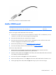
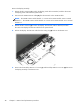
1. Release the ZIF connector (1) to which the display panel cable is attached, and then disconnect
the display panel cable from the system board.
2. Disconnect the WLAN antenna cables (2) from the terminals on the WLAN module.
NOTE: The WLAN antenna cable labeled “1” connects to the WLAN module “Main” terminal
labeled “1”. The WLAN antenna cable labeled “2” connects to the WLAN module “Aux” terminal
labeled “2”.
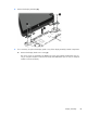
3. Release the ZIF connector (3) to which the display TouchScreen cable is attached, and then
disconnect the display TouchScreen cable from the system board.
4. Release the display TouchScreen cable from the routing clip (4) built into the bottom cover.
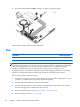
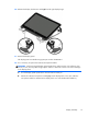
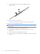
5. Remove the three Phillips PM2.5×5.7 screws (1) and the Phillips PM2.5×3.3 screw (2) that secure
the display assembly to the bottom cover.
48 Chapter 5 Removal and replacement procedures