HP Performance Optimized Datacenter 20c Site Preparation and Requirements Guide—North America Abstract This document provides site preparation guidance and requirements for the HP Performance Optimized Datacenter 20c (HP POD 20c).
© Copyright 2013 Hewlett-Packard Development Company, L.P. The information contained herein is subject to change without notice. The only warranties for HP products and services are set forth in the express warranty statements accompanying such products and services. Nothing herein should be construed as constituting an additional warranty. HP shall not be liable for technical or editorial errors or omissions contained herein.
Contents Overview ..................................................................................................................................... 5 About this document .................................................................................................................................. 5 Safety and NEC compliance ....................................................................................................................... 5 Site assessment .........................................
Project coordination................................................................................................................................. 21 Site planning .......................................................................................................................................... 22 HP POD 20c installation ................................................................................................................. 22 Appendix A: HP site assessment ..............................
Overview About this document This document outlines the site and preparation requirements for a 6 m (20 ft) HP POD 20c as it is being released in North America. The customer must provide a qualified architectural or consulting engineering team to generate site-specific documents for each HP POD 20c installation, including final site drawings.
Feature Specification Class Class1 Ambient temperature 2°C to 54°C (35.6°F to 129.2°F) Relative humidity 0% to 100% humidity • As part of the overall certification, relevant sections of the International Building Code have been applied as part of the design and evaluation. The current design supports wind loads up to 90 mph. Site assessment HP requires a detailed site assessment prior to planning and preparing the customer site location for the HP POD 20c.
HP POD 20c capacities HP POD 20c capacity limitations The capacity limitations for the HP POD 20c are separated into two categories: electrical power and mechanical cooling capacities. Both of these categories are interdependent and must be considered in conjunction with the overall customer requirements. Electrical power capacities (critical IT power) The electrical system of the HP POD 20c contains two main feeds, A and B, that are each rated at 400 A 480 V Delta 3-wire.
Site requirements Site pad The structural design of the HP POD 20c site pad must be based on the specific weight load of the complete POD solution with IT installed, as well as any additional equipment. During design calculations, HP recommends that you provide structural support along the entire perimeter of the POD and use the maximum allowable POD weight. Upon installation, the POD structure must be leveled to less than or equal to 0.5º.
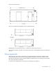
End 1 view clearances shown Top view keep-out and door swing clearances shown (shaded areas indicate the required clearance) Site requirements 9
Side view clearances shown Top view for multiple POD installation minimum clearances shown Adequate space around the HP POD 20c is necessary for minimum door clearance. These minimum clearances provide room for door opening only. Consider additional space as necessary for your site. Future expansions When selecting a site location, consider future space and accessibility requirements.
Grounding requirements The HP POD 20c structure and internal components are all bonded together. A common grounding electrode conductor connection point is provided on the utility-end of the hot aisle. WARNING: To avoid the risk of personal injury or electric shock, the HP POD 20c must be properly grounded (earthed) in accordance with national, regional, and local regulations.
Utilities Consider the proximity to required utilities, such as power, water, and network connections. While the required utilities can be brought to nearly any selected site, there is the potential for increased costs and decreased efficiency when the HP POD 20c is located farther from the utility sources. For utility clearance information, see "Dimensions and clearances (on page 8)." Humidifier water supply The HP POD 20c requires supply water for the humidifier.
Requirement Location Specification Humidifier drain Cold aisle side (1) 3.18 cm (1.25 in) drain line and 26.5 lpm (7 gpm) max Chilled water supply The following are the water quality requirements and specifications: • Closed-loop water must not contain any lime scale deposits or loose debris. • The temperature of the chilled water supplied to the HP POD 20c must be 12ºC to 24ºC (55ºF to 75ºF). CAUTION: Freezing water can cause a blockage and damage to the unit.
Feature Specification Facility input temperature to the HP POD 20c 12º to 24ºC (55º to 75ºF) Max design pressure 1,034 kPa (150 psi) HP POD 20c pressure drop 172.4 kPa (25 psi) HP POD 20c water flow rate 454 lpm (120 gpm*) Chilled water supply and return connections Two 7.62 cm (3 in) ASME B16.5 class #150 flanges *Measurement is in US gallons per minute.
These actions must be performed for all associated parts of the electrical power train. The majority of the details and factors required to complete these studies are associated with the existing installed facility infrastructure. CAUTION: Failure to complete these studies can cause serious issues with the electrical integration of the POD into your electrical system.
Supported facility connections Environmental control system The ECS developed for the HP water-cooled POD is a stand-alone control system that requires no external connections with an external site system, BMS, public or private Internet sites, cloud, or wireless system to properly control the POD operation. The ECS includes Modbus TCP/IP connections through which a variety of data can be retrieved.
End view shown Humidifier A dedicated water supply and approved drainage is required for the humidifier. For more information about the humidifier, see the HP Performance Optimized Datacenter 20c User Guide that is provided with the HP POD 20c. The following image shows the location of the humidifier drain and water supply. Side view shown IMPORTANT: Confirm with the AHJ that condensate water and rain water can be mixed in the same drainage.
HP POD 20c access control The HP POD 20c is equipped with standard key lock hardware for each personnel entry door and external electrical cabinet. Each personnel entry door includes a door access contact that can be connected to the customer facility security system.
Front view shown You must make the connections between the facility and the HP POD 20c. For configuration and installation instructions, consult with HP.
Environmental considerations Environmental risks • Avoid placing the HP POD 20c directly along a drainage path or in an area prone to flooding. • Verify that the HP POD 20c is properly grounded in accordance with national, regional, and local regulations, ordinances, codes, and the product specifications. Cold weather The HP POD 20c requires a site chilled water supply and return, humidifier supply and drain, and condensate drains. Extreme cold weather can cause damage to the supply and drain lines.
Site plan requirements and actions Completing a site assessment HP requires a detailed site assessment prior to planning and preparing the customer site location for the HP POD 20c. Consult with HP to schedule a site assessment.
• Ensure that the site safety and security programs are properly administered. • Interface directly with the HP installation project manager to ensure clear lines of communication during the installation and commissioning processes. Site planning A comprehensive site plan assists with the site design (MEP) and ensures the best possible HP POD 20c installation process.
• Assembly equipment locations Item Description 1 Crane 2 Reach 3 Truck 4 Area clear for scissors lift and forklift HP POD 20c lifting requirements WARNING: The only approved method for lifting the HP POD 20c is the use of a spreader bar harness. Lifting an HP POD 20c in any other manner can cause damage to the HP POD 20c and void your warranty. The harness and lifting connections must be perpendicular to the lifting blocks.
Additional structures If a customer-provided vestibule or other structure is installed and connected to the HP POD 20c, the following specifications must be maintained: • To protect the HP POD 20c and ensure a waterproof barrier, flashing must be installed to the exterior of the HP POD 20c in the location where the other structure is attached. • Access landings might be required to maintain the required access to the HP POD 20c electrical panels.
Appendix A: HP site assessment HP POD 20c site assessment checklist During a survey of the readiness of a proposed customer site for the HP POD 20c, the site is inspected for the following: • Accessibility of machinery for the transportation and installation of the HP POD 20c • Assessment of the suitability of the site infrastructure for installing the HP POD 20c and for supporting infrastructure preparation and serviceability requirements HP responsibilities Item Description Yes No N/A Initial 1.
Item Description Yes No N/A Initial Inspect the proposed installation site to confirm clearance requirements for installation and serviceability per the HP POD 20c specifications. Necessary clearances are determined, in part, based on the specific installation plans and infrastructure design. Location, orientation, and planned utilization can affect the necessary clearances. Consider future planning for the space around the installation site.
Item Description Yes No N/A Initial 15. Recommendations Following the HP installation site visit, analyze the data that is collected and prepare a report of findings. HP must identify potential obstacles to installation and make recommendations for any additional testing or changes to the installation plan. Customer responsibilities Item Description Initial 1.
Appendix B: Preparing for delivery Pre-delivery tasks Allow adequate time for planning, scheduling, obtaining permits, design approval, inspections, and so on. Installation prerequisites Before installing the HP POD 20c, verify that the following prerequisites are met: • All components are delivered to the facility. • The HP POD 20c and power distribution components are in the final location. • Facility power, water, and drainage are at the final location.
Item Description 10 15 Verify that the site location has clearances for the HP POD 20c installation, including any permanent structures, such as fences, walls, vestibules, and buildings. Verify that all utilities, overhead and underground, are identified to maintain required clearance. Verify that there is adequate clearance around the HP POD 20c for door operation, installation, and maintenance equipment.
Item Description 2 Verify that the chilled water supply temperature meets the minimum POD chilled water supply temperature of 12°C (55°F). Verify that a sufficient chilled water flow rate is available. 3 4 Initial If necessary, verify that the customer-required chilled water return temperatures can be attained. Power Requirements Item Description 1 Verify that the short circuit analysis, arc flash, and circuit breaker coordination studies are complete.
Appendix C: Regulatory compliance notices HP POD 20c regulatory compliance The HP POD 20c complies with the following regulatory standards.
• The HP POD 20c is designed for stationary installation outdoors in a Pollution Degree 3 environment, in restricted access locations, with field wiring terminals provided for permanent supply connections. • The HP POD 20c meets the following ratings. Feature Specification Category Rated Overvoltage Category III Protection Surge protection device Class Class1 Ambient temperature 2°C to 54°C (35.6°F to 129.
Glossary AHJ authority having jurisdiction APJ Asia Pacific Japan BMS building management system door A hinged portion of an enclosure that covers an opening. ECS environmental control system EMEA Europe, Middle East, and Africa EPO emergency power off equipment A general term, including fittings, devices, appliances, luminaires, apparatus, machinery, and the like used as a part of, or in connection with, a modular data center. (Source: NEC.
listed Equipment, materials, or services included in a list published by an organization that is acceptable to the authority having jurisdiction and concerned with evaluation of products or services, that maintains periodic inspection of production of listed equipment or materials or periodic evaluation of services, and whose listing states that either the equipment, material, or service meets appropriate designated standards potential of not more than 42.
Documentation feedback HP is committed to providing documentation that meets your needs. To help us improve the documentation, send any errors, suggestions, or comments to Documentation Feedback (mailto:docsfeedback@hp.com). Include the document title and part number, version number, or the URL when submitting your feedback.
Index A about this guide 5 areas prone to lightning or power surges 20 assembly 28 assembly area 22 C capacity limitations 7 clearance area 8 cold weather considerations 20 communication connections 18 connection portals 16 connections, additional 16 connections, facility 16 D delivery considerations 28 dimensions 8 drainage 12 E electrical power capacity 7 electrical system 14, 15 environmental considerations 20 environmental control system (ECS) 16 environmental risks 20 equipment, installation 22 F f
site planning considerations 22 site preparation 6 site preparation checklist 28 site requirements 8, 21 storage locations 23 supported facility connections 16 system capacity 7 U utilities 12 V vestibule specifications 24 W warranty information 32 water supply 12, 13 weight 8 Z zoning and permit requirements 21 Index 37