HP Performance Optimized Datacenter 20c Maintenance and Service Guide—China Abstract This guide provides maintenance and service guidance for the HP Performance Optimized Datacenter 20c (HP POD 20c).
© Copyright 2013 Hewlett-Packard Development Company, L.P. The information contained herein is subject to change without notice. The only warranties for HP products and services are set forth in the express warranty statements accompanying such products and services. Nothing herein should be construed as constituting an additional warranty. HP shall not be liable for technical or editorial errors or omissions contained herein.
Contents Illustrated parts catalog ................................................................................................................. 5 Structural component identification .............................................................................................................. 5 Life safety component identification ............................................................................................................. 6 Electrical power component identification .....................
Chilled water flow sensor ............................................................................................................... 47 Chilled water system temperature sensor .......................................................................................... 48 Chilled water temperature sensor internal components........................................................................ 49 Heat exchanger ..............................................................................................
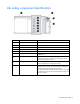
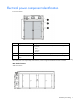
Illustrated parts catalog Structural component identification The HP POD 20c documentation frequently refers to the specific components of the HP POD 20c as shown in the following figure and described in the following table.
Life safety component identification Item Component Description 1 Exit sign locations Indicates the location of an exit 2 EPO strobe Red—An EPO event occurred and the HP POD 20c shut down.
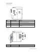
Electrical power component identification Front view shown Item Component Description 1 Demarcation box* Customer communication connection point for the following components: • • • ECS Security Phone 2 Fire box* Connection location for fire emergency and VESDAnet signals 3 380-415 VAC Y, 3-phase, 400 A Feed A and B power for IT critical loads busways and house power *The demarcation box and the fire box are communication data points that are provided on the POD by HP.
External panel labels Front view shown Item Electrical safety label Description 1 Danger sign Provides a reminder to users that the electrical panels must be accessed only by authorized personnel 2 Disconnect label Provides the order for disconnecting the electrical panels 3 Caution Cautions users about isolating power from the HP POD 20c.
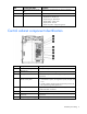
Item Electrical safety label Description 2 Lists the layout and designation for all circuit breakers 3 Panel schedule/circuit breaker table Fuse type table 4 Wire color code Lists the 380-415 Y/200-240 V color codes: Lists all fuse types and sizes • • • • • Purple/Brown—Phase A/L1 Purple/Orange—Phase B/L2 Purple/Yellow—Phase 3/L3 Purple/White—Neutral Green and yellow—Equipment ground Control cabinet component identification Item Component Description 1 An early warning laser scan smoke det
HP POD 20c racks The HP POD 20c contains a total of ten IT racks. CAUTION: If any racks contain empty RU space, use the HP POD 20c filler panels to maintain the efficiency of the HP POD 20c thermal system. Filler panels are available from HP in 10-pack quantities (part number AQ682A) and 100-pack quantities (part number AS993A). For more information about racks and network cabling, see the HP Performance Optimized Datacenter Networking Guide.
Hot aisle clearance Hot aisle clearance is defined as the distance from the rear of the rack to the hot aisle wall. The reference distance of 2.54 cm (16 in) must be considered when selecting IT infrastructure that will populate into the hot aisle. Replaceable components for China models The replaceable components in the following table can be replaced by qualified facilities personnel.
Spare part number Description 660787-001 SPS-Breaker 1SDA054870R1 660788-001 SPS-Fuse-Switch SV 9344.000 660789-001 SPS-Switch NH00 KTF-160 660794-001 SPS-Switch 1SAM150000R1005 660796-001 SPS-Terminal Cover 1SDA051415R0001 660802-001 SPS-Relay Assembly 62.32.8.230.0040 660803-001 SPS-Relay 1SVR630884R3300 660806-001 SPS-Relay Assembly 46.61.9.
Overview Installation considerations CAUTION: All plumbing to and from the HP POD 20c must be completed by a licensed plumber. All wiring in and around the HP POD 20c must be completed by a licensed electrician. Failure to comply with these instructions can impact your warranty and/or result in equipment damage. (Optional) Fire suppression system CAUTION: The POD fire suppression system is manufacturer designed, engineered, and installed to comply with national standards.
Removal and replacement procedures Buttons EPO button One EPO button is located on the POD interior near the main exit. A second EPO button is located on the POD exterior. Removing the EPO button 1. Grasp the bracket (1). 2. Remove the EPO button from the bracket (2). 3. Remove the contact modules from the bracket (3). 4. Disconnect the wires. Replacing the EPO button 1. Reconnect the wires. 2. Insert the button head (1) into the bracket (2).
3. Insert the contact modules (3) into the bracket (2). DIN rail components Control relay module The HP POD 20c uses analog and digital control relays to communicate sensed parameters to the ECS for overall POD control and reporting features. You need a screwdriver to remove and replace the control relay module. Removing the control relay module 1. Label the wired connections or take a picture to remember which wires to reconnect to the control relay module. 2.
4. Remove the control relay module (2). Replacing the control relay module 1. Align the control relay module with the mounting and power connections. 2. Slide the module until it clicks into the DIN rail. 3. Reconnect all wiring to the control relay module. Differential pressure sensor The HP POD 20c uses differential pressure sensing terminals located in the ECS cabinet to take pressure readings from the cold aisle, hot aisle, and cooling fan filters via sensing tubes.
Removing the differential pressure sensor 1. Using a small wrench, loosen the tube retaining lock nut. 2. Label the hose connector tube or take a picture to remember which hose to reconnect to the I/O system later. 3. Remove the hoses. 4. Pull the release tab at the top of the sensor to release it (1), grasp the edges of the sensor, and then pull forward to remove it (2). Replacing the differential pressure sensor 1.
Door position devices Magnetic contacts Magnetic contacts are located on all doors and cabinets. You need a screwdriver and scissors to remove and replace the magnetic contact. Removing the magnetic contacts 1. Remove the two screws that secure the upper magnet (1). 2. Cut the tie wrap (2) and loosen the nut on the POD structure that secures the wire. 3. Pull the wire all the way through to the point of entry or ECS panel (3). Replacing the magnetic contacts 1.
Electrical Busway drop box The internal electrical busways provide a location to connect each of the drop boxes, which then power the PDUs. Stagger the drop boxes on the electrical busways by connecting one drop box to busway #1 and connecting the next drop box to busway #2. A staggered configuration enables load balancing with the rack equipment and is necessary to ensure redundancy.
2. Disconnect the PDUs that are connected to the busway drop box (2). 3. Use a socket wrench to loosen and remove the bolt securing the busway drop box to the retaining hardware bracket (1). 4. Slide the hardware bracket to the right along the busway, completely disconnecting it from the busway drop box (2). WARNING: Use caution when removing and replacing the busway drop box. The drop box weighs approximately 9 kg (20 lb). 5.
Replacing the busway drop box WARNING: Use caution when removing and replacing the busway drop box. The drop box weighs approximately 9 kg (20 lb). 1. Place the silver drop box bracket onto the electrical busway where you want to replace the busway drop box (1). 2. Note the required rotation indicated on the drop box, insert the drop box into the drop box bracket on the electrical busway, and then rotate the drop box 90° until it locks into place (2).
6. Turn the power on by closing both breakers on the busway drop box (2). Fans IT cooling fan HP POD 20c fans operate at four speeds to maintain the cold-to-hot aisle differential pressure and hot aisle temperature setpoints that are programmed into the ECS. The fan speed adjusts to maintain the programmed setpoints. Do not manually adjust the fan speed. CAUTION: Power must be removed from the fan power assembly before removing or replacing a fan or fan bank.
The HP POD 20c has 3 banks of 4 fans, for a total of 12 fans per zone. The fans circulate cool air from the heat exchangers throughout the POD. The three fan banks are located in the access hatches that are in the ceiling of the POD. The IT cooling fan has four screws and a power connection. You need a screwdriver to remove and replace the IT cooling fan. Removing the IT cooling fan HP recommends leaving the fans in AUTO mode during normal operation. 1.
Replacing the IT cooling fan 1. Position the IT cooling fan (1). 2. Replace the four screws (2). 3. Reconnect the power harness. 4. Close the access hatch door. 5. Return the fan bank to AUTO mode. Ventilation fan The ventilation fan is located between the ECS cabinet and the transformer cabinet. The purpose of the fan is to provide proper ventilation to the electrical components within the ECS and electrical cabinets.
Removing the Rittal SK 3326 ventilation fan 1. Open the ECS cabinet door. 2. Label and disconnect the fan wires. 3. Remove the four screws (1). 4. Pull the fan module forward to remove it (2). Replacing the Rittal SK 3326 ventilation fan 1. Insert the fan module into the screwless spring terminal (1). 2. Rotate the fan module clockwise until it is seated (2). 3. Reconnect the fan wires. 4. Insert the ventilation fan into the ventilation fan cut-out hole. 5. Close the ECS cabinet door.
The Rittal SK 3326 ventilation fan has been discontinued, so if it malfunctions, you must order the Rittal SK 3243 ventilation fan. To install the new fan, see the installation instructions included with the fan. Filters Heat exchanger air filters There are two heat exchanger air filters per cooling zone for a total of six filters. You do not need any tools to remove or replace the heat exchanger air filter. Removing the heat exchanger air filter 1.
2. Push in the bottom corners of the filter until the locking tabs engage and the filter clicks into place. VESDA filter The VESDA filter sensor notifies you through the ECS when a filter must be changed. HP recommends periodically inspecting and changing each VESDA filter. A VESDA filter can be replaced during normal HP POD 20c operation. You need a Phillips-head screwdriver for installation. Removing the VESDA filter 1. Remove the filter cover on the front of the VESDA unit.
2. Remove the 10mm screw that secures the VESDA filter (1), and then remove the filter (2). Replacing the VESDA filter 1. Insert the new VESDA filter (1), and then replace the 10mm screw that secures the filter (2). 2. Replace the VESDA filter cover. Rittal SK 3326 ventilation fan filter The ventilation fan filter is located behind the louvered grille. IMPORTANT: Check the fan filter quarterly to be sure that it is clean. You need a screwdriver for installation.
Removing the Rittal SK 3326 ventilation fan filter 1. Insert a screwdriver into the bottom right corner of the louvered grille and rotate it counterclockwise (1) to loosen the grille. 2. Grasp the louvered grille and pull forward to remove it (2). 3. Remove the old filter (3). Replacing the Rittal SK 3326 ventilation fan filter 1. Insert the new filter (1). 2. Close the louvered grille (2).
Indicators ECS touchscreen and EPO indicators The ECS touchscreen and EPO indicators are located on the door to the control panel. The touchscreen enables you to easily configure the environmental parameters, access data, and monitor environmental, life safety, and access control conditions within the HP POD 20c. The EPO indicators provide EPO status. The EPO key control and EPO reset button enable you to adjust the EPO system mode.
Removing the ECS EPO LED indicators 1. Remove the screw from the mounting base (1). 2. Remove the contact block from the mounting base (2). 3. Pull the ECS push button, selector switch, or LED light out of the mounting base (3). Replacing the ECS EPO LED indicators 1. Insert the ECS push button, selector switch, or LED light into the mounting base (1). 2. Attach the contact block to the mounting base (2). 3. Attach the screw to the mounting base (3).
Lights LED light The HP POD 20c contains three LED lights in the cold aisle and three LED lights in the hot aisle. You need a screwdriver to remove and replace the LED light. Removing the LED light You need a screwdriver to remove and replace the LED light. 1. Disconnect power from the LED light. 2. Remove the screws (1). 3. Remove the LED light assembly (2). Replacing the LED light 1. Place the LED light where you want to secure it (1). 2. Insert the screws (2).
3. Reconnect power to the LED light. Sensors Heat exchanger condensate drain pan sensors The HP POD 20c - China model includes three heat exchanger condensate drain pan sensors. One drain pan sensor is located in the drain tray below each set of the heat exchangers. Three sensors are also located in the chilled water supply and return header drain pans, one in each of the three sections.
5. Route the wire from the junction box to the sensor location, and then remove the sensor. Replacing the drain pan sensor 1. Position the sensor in the drain pan. 2. Route the wire to the junction box and reconnect the wire. 3. Close the center fan bank in the cold aisle of the affected sensor. Chilled water supply and return header drain pan sensors The HP POD 20c includes three heat exchanger condensate drains. One drain pan sensor is located in the drain tray below each set of heat exchangers.
2. Route the wire to the associated zone satellite box. 3. Connect the sensor wire to the appropriate port on the satellite box terminal. Humidistat The humidistat is located in the cold aisle humidifier bump out. You need a Phillips-head screwdriver and a flathead screwdriver for installation. Removing the humidistat 1. Press the power button on the outside of the humidifier to power down the humidifier. 2. Open and danger tag the associated circuit breaker in the ECS cabinet.
b. Use a flathead screwdriver to the press the release button (1), and then pull the front panel from the bottom to detach the panel (2). The two parts remain connected by a flat cable. 4. Squeeze the two terminal cover fins to remove the cables from the terminal block. 5. Remove the screws securing the mounting base to the wall. Replacing the humidistat 1. Detach the front panel of the replacement humidistat from the mounting base. a.
b. Use a flathead screwdriver to the press the release button (1), and then pull the front panel from the bottom to detach the panel (2). The two parts remain connected by a flat cable. 2. Secure the mounting base to the wall using the screws provided. 3. Squeeze the two terminal cover fins to remove the terminal covers. 4. Make the required connections by running the connection cables through the center hole in the bottom of the mounting base and connecting the cables to the terminal block. 5.
Removing the humidity sensor 1. Remove the four screws that secure the sensor cover (1), and then remove the cover (2). 2. Remove the two self-tapping screws (3). 3. Identify the sensor wires. 4. Disconnect the sensor wires. 5. Remove the two retaining screws, and then remove the humidity sensor housing from the wall (4). Replacing the humidity sensor 1. Re-attach the humidity sensor housing to the wall (1). 2. Replace the two self-tapping screws (2). 3.
5. Replace the four screws that secure the sensor cover (4). Chilled water system temperature sensor The HP POD 20c contains two chilled water header temperature sensors. One is located in the chilled water supply header and one is located in the chilled water return header. HP highly recommends replacing sensor internal components before replacing the entire sensor. For more information, see replacing the entire sensor. You need a wrench and a screwdriver to remove and replace the sensor.
4. Rotate the immersion sleeve counterclockwise (1), and then pull forward to remove the entire sensor from the chilled water header (2). Replacing the temperature sensor in the chilled water system 1. Insert the new sensor probe into the chilled water header (1). 2. Rotate the immersion sleeve clockwise to secure the sensor onto the header (2). 3. Reconnect the wiring, replace the sensor cover, and replace the removed insulation.
Removing the chilled water temperature sensor internal components 1. Remove the four screws from the sensor cover (1). 2. Remove the sensor cover (2). 3. Label and disconnect the sensor wires. 4. Remove the two screws from the chilled water temperature sensor circuit board (1). 5. Remove the chilled water temperature sensor circuit board (2). Replacing the chilled water temperature sensor internal components 1. Replace the chilled water temperature sensor circuit board (1).
2. Replace the two screws to secure the chilled water temperature sensor circuit board (2). 3. Reconnect the sensor wires. 4. Replace the four screws to secure the chilled water temperature sensor cover (2). 5. Replace the chilled water temperature sensor cover (1).
Temperature sensor (cold aisle) The HP POD 20c contains three temperature sensors in the cold aisle. You need a screwdriver and scissors to remove and replace the cold aisle temperature sensor. Removing the cold aisle temperature sensor 1. Remove the four screws that secure the cold aisle temperature sensor cover (1), and then remove the cover (2). 2. Label the cold aisle temperature sensor wires or take a picture to remember which wires to reconnect later. 3. Disconnect the wires. 4.
4. Replace the cold-aisle temperature sensor cover (1). 5. Replace the four screws that secure the cold aisle temperature sensor cover (2). Temperature sensors (hot aisle) The HP POD 20c contains three temperature sensors in the hot-aisle. You need a screwdriver to remove and replace the hot aisle temperature sensors. Removing the hot aisle temperature sensor 1. Remove the four screws (1) that secure the hot-aisle temperature sensor cover, and then remove the cover (2). 2.
4. Remove the two retaining screws, and then remove the hot-aisle temperature sensor housing from the wall. Replacing the hot aisle temperature sensor 1. Reconnect the wires to the hot aisle temperature sensor. 2. Reconnect the wires. 3. Re-attach the hot-aisle temperature sensor housing to the wall using the two retaining screws. 4. Replace the hot-aisle temperature sensor cover (1). 5. Replace the four screws that secure the hot-aisle temperature sensor cover (2).
You need a wrench to remove and replace the pressure sensors. Removing the chilled water supply and return header pressure sensor 1. Observe the sensor alignment direction. 2. Disconnect the sensor wiring. 3. Using a wrench, disconnect the sensor from the tubing connection by rotating the nut counterclockwise. 4. Remove the sensor from the water piping. Replacing the chilled water supply and return header pressure sensor 1. Position the sensor as it was prior to removal. 2.
Chilled water flow sensor You need a wrench to remove and replace the chilled water flow sensor. Removing the chilled water flow sensor 1. Label the wired connections or take a picture to remember which wires to reconnect to the chilled water flow sensor. 2. Disconnect the wires from the back of the sensor. 3. Using a wrench, rotate the sensor locking gland counter-clockwise (1). 4. Pull forward to remove the sensor from the water piping (2). Replacing the chilled water flow sensor 1.
4. Using a wrench, rotate the sensor locking gland clockwise to tighten it (2). Chilled water system temperature sensor The HP POD 20c contains two chilled water header temperature sensors. One is located in the chilled water supply header and one is located in the chilled water return header. HP highly recommends replacing sensor internal components before replacing the entire sensor. For more information, see replacing the entire sensor.
4. Rotate the immersion sleeve counterclockwise (1), and then pull forward to remove the entire sensor from the chilled water header (2). Replacing the temperature sensor in the chilled water system 1. Insert the new sensor probe into the chilled water header (1). 2. Rotate the immersion sleeve clockwise to secure the sensor onto the header (2). 3. Reconnect the wiring, replace the sensor cover, and replace the removed insulation.
Removing the chilled water temperature sensor internal components 1. Remove the four screws from the sensor cover (1). 2. Remove the sensor cover (2). 3. Label and disconnect the sensor wires. 4. Remove the two screws from the chilled water temperature sensor circuit board (1). 5. Remove the chilled water temperature sensor circuit board (2). Replacing the chilled water temperature sensor internal components 1. Replace the chilled water temperature sensor circuit board (1).
2. Replace the two screws to secure the chilled water temperature sensor circuit board (2). 3. Reconnect the sensor wires. 4. Replace the four screws to secure the chilled water temperature sensor cover (2). 5. Replace the chilled water temperature sensor cover (1). Heat exchanger HP service personnel is required to replace this spare component. Please contact HP Services for assistance.
Humidifier The humidifier is located in the cold aisle humidifier bump out. You need a Phillips-head screwdriver for installation. Removing the humidifier 1. Hold the drain button on the humidifier exterior until the humidifier cylinder drains completely. 2. Press the power button on the outside of the humidifier to power down the humidifier. 3. Close the water supply isolation valve on the HP POD 20c exterior. 4.
6. Remove the four screws on the corners of the humidifier cover (1), and then remove the cover (2). 7. Locate the power board and disconnect the two internal electrical wires. 8. Disconnect the drain (1). 9. Disconnect the humidifier from the water supply line (2). 10. Disconnect and remove the external electrical wiring from the housing (3).
11. Remove the four screws that secure the humidifier body to the wall (1), and then remove the humidifier (2). Replacing the humidifier 1. Replace the humidifier (1), and then secure the humidifier to the wall with four screws (2). 2. Connect the drain (1). 3. Connect the humidifier to the water supply line (2).
4. Route and connect the external electrical wiring to the housing (3). 5. Locate the power board and connect the two internal electrical wires. 6. Replace the humidifier cover (1), and then secure the cover with four screws (2). 7. Open the water supply isolation valve on the HP POD 20c exterior. 8. Connect the water supply line to the humidifier on the HP POD 20c exterior. 9. Close the associated circuit breaker in the ECS cabinet. 10.
Humidistat (if installed) The humidistat is located in the cold aisle humidifier bump out. You need a screwdriver to remove and replace the humidistat. Removing the humidistat 1. Press the power button on the outside of the humidifier to power down the humidifier. 2. Open and danger tag the associated circuit breaker in the ECS cabinet. The circuit breakers are identified on the panel schedule. 3. Detach the front panel of the humidistat from the mounting base: a.
b. Use a flathead screwdriver to press the release button (1), and then pull the front panel from the bottom to detach the panel (2). The two parts remain connected by a flat cable. 4. Squeeze the two terminal cover fins to remove the cables from the terminal block. 5. Remove the screws securing the mounting base to the wall. Replacing the humidistat 1. Detach the front panel of the replacement humidistat from the mounting base. a.
b. Use a flathead screwdriver to the press the release button (1), and then pull the front panel from the bottom to detach the panel (2). The two parts remain connected by a flat cable. 2. Secure the mounting base to the wall using the screws provided. 3. Squeeze the two terminal cover fins to remove the terminal covers. 4. Make the required connections by running the connection cables through the center hole in the bottom of the mounting base and connecting the cables to the terminal block. 5.
2. Remove the valve (2). Replacing the external chilled water isolation valve 1. Replace the valve (1). 2. Secure the valve with eight bolts (2). External pressure gauge isolation valve The external pressure gauge isolation valve is located on top of the HP POD 20c. You need an adjustable wrench or an appropriately sized box wrench for installation. Removing the external pressure gauge isolation valve 1.
2. Remove the valve (2). Replacing the external pressure gauge isolation valve 1. Insert the new valve (1). 2. Tighten the connection (2).
Periodic maintenance Periodic maintenance overview Perform periodic inspections on the components in this section to be sure that the HP POD 20c continues to perform within the designed parameters.
Component to be inspected Task Frequency Capable Party Condensate drain lines and p-trap Inspect and verify that: Quarterly Qualified personnel • Clean and clear debris as necessary.
CAUTION: If a serious leak develops, shut down the POD immediately and isolate the chilled water cooling system from the site. Contact HP immediately to initiate a field service call. Do not attempt to repair the chilled water cooling system. Attempting to self-repair the chilled water cooling system during the warranty or service contract period shifts all liability to you. IMPORTANT: Power down the POD after a leak is detected.
Component to be inspected Task Frequency Capable Party Humidifier drains Quarterly Qualified personnel Quarterly Qualified personnel Quarterly Qualified personnel — Put the humidifier in system flush mode and inspect drain flow and water supply flow. Inspect, clean, and/or replace as necessary. Inspect for any internal or external water leaks, repair or replace leaking components. Using LLS, verify proper cylinder operation.
Component to be inspected Task Frequency Capable Party — POD SHUT DOWN REQUIRED Conduct torque checks on the following: Annually Licensed electrician Grounding system residence test using the DUCTOR method POD SHUT DOWN REQUIRED Ground and grounding connection/lug located internal to each electrical panel torque test. Clean and re-tighten as necessary. Service entrance grounding ground-rod/ground well and grounding connection/lug located external to the POD torque test.
Component to be inspected Task Frequency Capable Party — Compare the following with site indications (if available): Annually Qualified personnel • • • — Lighting CWS/CWR temperature CWS/CWR pressure Flow rate (if possible) (Investigate discrepancies, trouble shoot, and replace as necessary.) Annually POD SHUT DOWN REQUIRED Calibrate (zero out) POD differential pressure sensors. (Investigate discrepancies, trouble shoot, and replace as necessary.
Component to be inspected Task — Inspect the door operation and Annually inspect the door gaskets for water and air leaks. Visually inspect the paint. Perform Annually prep and touch-up as necessary. — Frequency Capable Party Qualified personnel Qualified personnel Life safety Component to be inspected Task Manual EPO shunt trip Annually EPO FUNCTIONAL TEST Manually initiate EPO with the internal and external push buttons (if installed) in succession. (Verify all shunt-trips on all panels trip.
Access control Component to be inspected Task System functional test Visual inspection and operational Annually test of door access contact switches Visual inspection and operational Annually test of the following: — • • • Frequency Capable Party Qualified personnel Qualified personnel Door access card readers Electric strikes Door release switches at each personnel door and/or in each personnel door panic bar Third-party components All maintenance for third-party equipment will be defined by the
Specifications General HP POD 20c specifications Features Specifications Overall dimensions • • • Height—3.05 m (10 ft) Length—6.10 m (20 ft) Width—2.43 m (7.
Fire alarm panel connections The electrical layout of the fire alarm system is as described in the schematic drawing supplied with the HP POD 20c. Water specifications The following table describes the chilled water system specifications for the HP POD 20c. Feature Specification Facility input temperature to the HP POD 20c 12º to 24ºC (55º to 75ºF) Working pressure 1,034 kPa (150 psi) HP POD 20c pressure drop 172.
Feature Specification Operating humidity • • 0% to 100% external 10% to 90% non-condensing internal Non-operating humidity* • • 5% to 95% relative non-condensing 39ºC (102ºF) maximum wet bulb temperature Operating altitude -76.2 m to 3,048 m (-250 ft to 10,000 ft) Non-operating altitude -76.2 m to 9,144 m (-250 ft to 30,000 ft) *For non-operating specifications, consider the temperature of computer and IT equipment inside the HP POD 20c.
Contacting HP Before you contact HP Be sure to have the following information available before you call HP: • Active Health System log (HP ProLiant Gen8 or later products) Download and have available an Active Health System log for 3 days before the failure was detected. For more information, see the HP iLO 4 User Guide or HP Intelligent Provisioning User Guide on the HP website (http://www.hp.com/go/ilo/docs).
Regulatory information HP POD 20c regulatory compliance IMPORTANT: All regulatory information applies to HP POD 20c—International and HP POD 20c—North America only. HP POD 20c - China is designed according to the same requirements, but it is not a listed product and has not been verified by the governing body. The HP POD 20c complies with the following regulatory standards.
• The electrical connections of the HP POD 20c are evaluated as feeder connections for connection to an existing facility, and are not suitable as "service entrance" for connection to the utility. • The HP POD 20c is designed for stationary installation outdoors in a Pollution Degree 3 environment, in restricted access locations, with field wiring terminals provided for permanent supply connections. • The HP POD 20c meets the following ratings.
• the device manufacturer’s (or distributor’s) name, model number and serial number; • the name, address, and license number of the person receiving the device; and • the date of the transfer. Reports should be sent to Director, Office of Federal and State Materials and Environmental Management Programs, ATTN: GLTS, U.S. Nuclear Regulatory Commission, Washington, D.C. 20555-0001. For more information, see the Fact Sheet on Tritium EXIT Signs on the NRC website (http://www.nrc.
Glossary branch circuit The conductors and components following the last overcurrent protective device protecting a load. cover An unhinged portion of an enclosure that covers an opening. door A hinged portion of an enclosure that covers an opening. ECS environmental control system EPO emergency power off equipment A general term, including fittings, devices, appliances, luminaries, apparatus, machinery, and the like used as a part of, or in connection with, a modular data center. (Source: NEC.
RU rack units SOW statement of work structure Enclosure of sufficient size to enable entry of personnel.
Documentation feedback HP is committed to providing documentation that meets your needs. To help us improve the documentation, send any errors, suggestions, or comments to Documentation Feedback (mailto:docsfeedback@hp.com). Include the document title and part number, version number, or the URL when submitting your feedback.
Index A aisle clearances 10 authorized reseller 72 B before you contact HP 72 busway drop box, removing 19 busway drop box, replacing 21 busway drop boxes 19 buttons 13, 14 C chilled water flow sensor 47 chilled water flow sensor, removing 47 chilled water flow sensor, replacing 47 chilled water supply and return header pressure sensors 45 chilled water supply and return header pressure sensors, removing 46 chilled water supply and return header pressure sensors, replacing 46 chilled water system temperat
fan filter, replacing 26, 29 fan filters 26 fans 22 Federal Communications Commission (FCC) notice 75 filter 26, 27 fire alarm and suppression system 66 fire suppression 13 fluid system components 45 G L leak detection 62 leak isolation 62 LED light 32 life safety components 6 life safety maintenance 67 light, removing 32 light, replacing 32 lighting 32 lights 32 general specifications 69 M H magnetic contact 18 magnetic contact, removing 18 magnetic contact, replacing 18 maintenance, access control 6
required tools 14 S safety and NEC compliance 73 safety considerations 75 safety information 75 sensors 33 sensors, drain pan 33 sensors, humidity 37 series number 75 spare part numbers 5, 11 specifications 69 specifications, electrical 69 specifications, environmental 69, 70 specifications, general 69 specifications, rack 70 specifications, water 70 structural components 5 structure maintenance 66 T technical support 72 telephone numbers 72 temperature sensors, cold aisle 43 temperature sensors, cold ais