HP Performance Optimized Datacenter 40c G2 Maintenance and Service Guide Abstract This guide provides maintenance and service guidance for the HP Performance Optimized Datacenter 40c (HP POD 40c G2).
© Copyright 2012 Hewlett-Packard Development Company, L.P. The information contained herein is subject to change without notice. The only warranties for HP products and services are set forth in the express warranty statements accompanying such products and services. Nothing herein should be construed as constituting an additional warranty. HP shall not be liable for technical or editorial errors or omissions contained herein.
Contents Illustrated parts catalog ................................................................................................................. 6 Structural component identification .............................................................................................................. 6 Parts and part number identification ................................................................................................... 6 Life safety component identification ....................................
External pressure gauge isolation valve ...................................................................................................... 37 Removing the external pressure gauge isolation valve ........................................................................ 37 Replacing the external pressure gauge isolation valve ........................................................................ 37 Fan .......................................................................................................
Rack specifications .................................................................................................................................. 71 Thermal and air flow performance ............................................................................................................. 71 Environmental specifications ..................................................................................................................... 71 Optional features specifications..............................
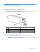
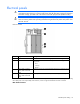
Illustrated parts catalog Structural component identification The HP POD 40c G2 documentation frequently refers to the specific components of the HP POD 40c G2 as shown in the following figure and described in the following table.
• Regulatory compliance identification number—This product has been assigned a unique regulatory model number and is located on the door to the control panel inside the cold aisle of the HP POD 40c G2, as shown in the following figure. • CSC Safety Approval placard—Each HP POD 40c G2 has a CSC Safety Approval placard that includes the model number, serial number, and proof load. The CSC Safety Approval placard is located on the cargo end of the HP POD 40c G2, as shown in the following figure.
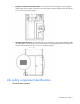
Top view shown Item Component Description 1 Exit sign locations Indicates the location of an exit 2 Fire strobe light Indicates a fire alarm condition within the HP POD 40c G2 3 EPO button Disconnects the HP POD 40c G2 from main power feeds 4 Fire alarm manual pull* Enables manual initiation of the fire system, which includes activating the interior and exterior fire strobe lights and the optional fire suppression system 5 Fire suppression abort button* Aborts the fire suppression system.
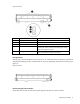
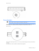
Top view shown Power feeders IMPORTANT: A licensed electrician must connect the power according to all local and national electrical codes, and must comply with manufacturer specifications. The HP POD 40c G2 has eight power feeder couplings that provide the entrance for power to the POD. The power feeders route into the top of each electrical panel on the end of the HP POD 40c G2. Top view shown The top of each electrical panel has four 10.
Electrical panels WARNING: To avoid the risk of personal injury or loss of life, all personnel must comply with PPE requirements when opening or working inside areas of the HP POD 40c G2 that are marked as hazardous voltage, per NFPA 70E in accordance with NEC (NA) and IEC (EMEA and APJ). WARNING: To avoid the risk of personal injury or loss of life, all personnel must comply with electrical warning labels when operating and maintaining the electrical panels and systems of the HP POD 40c G2.
End view shown Cooling system component identification The heat exchanger access hatches are located on top of the POD. The hatches are coated with a durable finish to prevent corrosion.
CAUTION: If any racks contain empty RU space, use the HP POD 40c G2 filler panels to maintain the efficiency of the HP POD 40c G2 thermal system. Filler panels are available from HP in 10-pack quantities (part number AQ682A) and 100-pack quantities (part number AS993A). For more information about racks and network cabling, see the HP Performance Optimized Datacenter Networking Guide. Replaceable spare parts The spare parts in the following table can be replaced by qualified facilities personnel.
Spare part number Description 637138-001 EPO switch cover w/ horn 637139-001 EPO BUTTON 637140-001 ELECTRIC VALVE ACTUATOR 637141-001 BUTTERFLY VALVE 637371-001 SPS-FAN 235 CFM 637372-001 Temperature sensor duct 637373-001 SPS-SENSOR LEAKAGE 664744-001 SPS-SENSOR TEMP RH NEMA 4 4 20mA OUT 664868-001 SPS-INDICATOR LED 6 24VDC GREEN 671748-001 SPS-SENSOR PRESSURE GAUGE 160 PSI 671749-001 SPS-SENSOR FLOW METER GEMU 671756-001 SPS-HUMIDISTAT GEN M3 VS-005 (Mfg PN) Filter, replacement, V
The spare parts in the following table must be replaced by a licensed fire safety contractor. IMPORTANT: These parts must be replaced by a licensed fire safety contractor according to all local and regional fire codes, and in compliance with manufacturer specifications.
Removal and replacement procedures Safety considerations The HP POD 40c G2 is listed to the UL 69050 standard as an Information Technology Product and Classified according to the NEC, NFPA-70, 2008. The HP POD 40c G2 is not suitable for long term personnel occupancy. The safety information is specific to the people operating and maintaining the components of the HP POD 40c G2. IMPORTANT: All plumbing to and from the HP POD 40c G2 must be completed by a licensed plumber.
The HP standard suppression system includes a Novec 1230 clean agent system. However, if the customer or local AHJ requires specific modifications or a replacement, HP can assist in these actions at the expense of the customer. HP does not certify that the fire suppression system installed in the HP POD 40c G2 meets all local and jurisdictional requirements.
2. Pull the filter down through the frame channels to remove the filter. Replacing the air filter 1. Angle the filter to position the top corners in the frame channels, and then push the filter up to the top of the frame. 2. Press in the bottom corners of the filter until the locking tabs engage and the filter clicks into place.
Busway drop box The internal electrical busways provide a location to connect each of the drop boxes, which then power the PDUs. Stagger the drop boxes on the electrical busways by connecting one drop box to busway #1 and connecting the next drop box to busway #2. A staggered configuration enables load balancing with the rack equipment and is necessary to ensure redundancy. You need a socket wrench for installation.
4. Slide the hardware bracket to the right along the busway, completely disconnecting it from the busway drop box (2). WARNING: Use caution when removing and replacing the busway drop box. The drop box weighs approximately 9 kg (20 lb). 5. Rotate the busway drop box 90° so that it is perpendicular to the electrical busway, and then remove the drop box from the electrical busway (3). Replacing the busway drop box WARNING: Use caution when removing and replacing the busway drop box.
4. Secure the busway drop box to the retaining hardware bracket by using a socket wrench to insert and tighten a bolt (4). 5. Connect the PDUs to the busway drop box (1). 6. Turn the power on by closing both breakers on the busway drop box (2). Differential pressure sensor The differential pressure sensors are located in the cold aisle. You need a Phillips-head screwdriver for installation.
Removing the differential pressure sensor 1. Label the pressure sensor tube connection locations, and then remove the tubes from the differential pressure sensor. 2. Label the sensor wire connection locations, loosen the screws securing the sensor wires, and then remove the sensor wires. 3. Remove the two nuts (1) and two bolts (2) securing the differential pressure sensor, and then remove the differential pressure sensor. Replacing the differential pressure sensor 1.
Door position contact Door position contacts are located on all doors and cabinets. You need a Phillips-head screwdriver and scissors for installation. Removing the door position contact 1. Remove the two screws securing the upper magnet (1). 2. Cut the tie wrap (2) and loosen the nut on the HP POD 40c G2 structure that secures the wire. 3. Pull the wire all the way through to the point of entry or ECS panel (3). Replacing the door position contact 1.
Drain pan sensor The HP POD 40c G2 includes six heat exchanger condensate drains. One drain pan sensor is located in the drain tray below each set of heat exchangers. Two sensors are also located in the header drain pans, one in cooling zone 2 and one in cooling zone 5. The normally-open circuit is closed when the probes of the drain pan sensor become wet, which allows 24 VDC to travel back to the ECS panel and trigger the alarm.
3. Pull the wire through from the satellite box to the sensor location, and then remove the sensor. Heat exchanger drain pan sensor -orHeader drain pan sensor Replacing the drain pan sensor 1. Position the sensor in the drain pan.
Header drain pan sensor 2. Route the wire through the flex tubing to the associated zone satellite box. 3. Connect the sensor wire to the appropriate port on the satellite box terminal. Heat exchanger drain pan sensor -orHeader drain pan sensor 4. If you are replacing a heat exchanger drain pan sensor, do the following: a. Replace the fan bank you removed, if applicable. For more information, see "Replacing the fan bank (on page 41)." b. Replace the fan you removed, if applicable.
ECS touchscreen The ECS touchscreen is located on the door to the control panel inside the cold aisle of the HP POD 40c G2. You need a Phillips-head screwdriver for installation. Removing the ECS touchscreen 1. Disconnect the cables attached to the back of the ECS touchscreen. 2. Remove the eight screws on the back of the door that secure the ECS touchscreen (1), and then push the ESC touchscreen through the front of the door to remove the ECS touchscreen (2).
Replacing the ECS touchscreen 1. Replace the ESC touchscreen through the front of the door (1), and then secure the ECS touchscreen to the back of the door with eight screws (2). 2. Connect the cables to the back of the ECS touchscreen. EPO button There are two EPO buttons, one by each personnel access door in the HP POD 40c G2. You need a Phillips-head screwdriver for installation.
Removing the EPO button 1. Remove the two screws securing the tamper cover (1), and then remove the tamper cover (2). 2. Remove the four screws securing the EPO button (1), and then remove the EPO button (2).
Replacing the EPO button 1. Replace the EPO button (1), and then replace the four screws that secure the EPO button (2). 2. Replace the tamper cover (1), and then replace the two screws that secure the tamper cover (2).
EPO LED indicators The ECS cabinet contains white (1, 3), red (2), yellow (4), and green (5) EPO LED indicators. Tools are not required for installation. Removing the EPO LED indicator 1. On the back of the ECS cabinet door, push the gray tab on the EPO LED indicator module down to release the module (1), and then pull the module out of the door (2).
2. Unscrew the EPO LED indicator bulb. Replacing the EPO LED indicator 1. Screw the new EPO LED indicator bulb into the module.
2. Push the module into the slot on the back of the ECS cabinet door until it clicks into place. EPO thermister Two EPO thermisters are located in the hot aisle, one in cooling zone 2 and one in cooling zone 5. While the thermisters are not technically at-temperature monitoring devices, when the hot aisle temperature reaches 60ºC (140ºF), the thermister switch closes. When both thermister switches are closed, the EPO system initiates an emergency shutdown. You need scissors for installation.
2. Secure the thermister with tie wraps (2). External chilled water flow actuator The external chilled water flow actuator is located on top of the HP POD 40c G2. You need a wrench for installation. Removing the external chilled water flow actuator 1. Open and danger tag the associated circuit breaker in the ECS cabinet. The circuit breakers are identified on the panel schedule.
2. Remove the four bolts securing the face plate (1), and then remove the face plate (2). 3. Disconnect the power to the actuator. 4. Remove the four bolts securing the actuator (1), and then remove the actuator (2).
Replacing the external chilled water flow actuator 1. Replace the actuator (1), and then secure the actuator using four bolts (2). 2. Connect the power to the actuator. 3. Replace the actuator face plate (1), and then secure the face plate with four bolts (2). 4. Close the associated circuit breaker in the ECS cabinet. External chilled water flow valve The external chilled water flow valve is the butterfly valve located on top of the HP POD 40c G2. You need a wrench for installation.
Removing the external chilled water flow valve 1. Remove the external chilled water flow actuator. For detailed instructions, see "Removing the external chilled water flow actuator (on page 33)." 2. Remove the eight bolts surrounding the valve (1), and then remove the valve (2). Replacing the external chilled water flow valve 1. Replace the valve (1), and then secure the valve with eight bolts (2). 2. Replace the external chilled water flow actuator.
External pressure gauge isolation valve The external pressure gauge isolation valve is located on top of the HP POD 40c G2. You need an adjustable wrench or an appropriately sized box wrench for installation. Removing the external pressure gauge isolation valve Loosen the connection securing the valve (1), and then remove the valve (2). Replacing the external pressure gauge isolation valve Insert the new valve (1), and then tighten the connection (2).
Fan There are 18 fans per cooling zone. CAUTION: Power must be removed from the fan power assembly before removing or replacing a fan or fan bank. You need a Phillips-head screwdriver for installation. Removing the fan 1. Disconnect both power supplies from the fan power assembly.
2. Remove the three screws that secure the fan in the assembly (1), and then partially remove the fan by pulling it straight out (2). 3. Disconnect the wire. 4. Remove the fan from the assembly. Replacing the fan 1. Connect the wire. 2. Insert the fan into the assembly and push until the fan is fully seated (1). 3. Secure the fan with three screws (2). 4. Connect the power supplies to the fan power assembly.
Fan bank There are three fan banks per cooling zone. CAUTION: Power must be removed from the fan power assembly before removing or replacing a fan or fan bank. You need a Phillips-head screwdriver for installation. Removing the fan bank 1. Disconnect both power supplies from the fan power assembly. 2. Remove the fan bank wire harness (1). 3. Remove the six screws that secure the fan bank (2).
4. Remove the fan bank by pulling it straight out (3). Replacing the fan bank 1. Insert the fan bank (1). 2. Secure the fan bank with six screws (2). 3. Replace the fan bank wire harness (3). 4. Connect the power supplies to the fan power assembly.
Fire strobe light The HP POD 40c G2 contains an internal fire alarm strobe light in the cold aisle and an external fire alarm strobe light at the standard personnel entry door. You need a Phillips-head screwdriver for installation. Removing the fire strobe light 1. Remove the four screw cover plates (1). 2. Remove the four screws securing the components (2), and then disconnect the wiring. 3. Remove the electric sounder with strobe, the semi-flush plate, and the standard back box (3).
Replacing the fire strobe light 1. Assemble the standard back box, the semi-flush plate, and the electric sounder with strobe (1), and then attach the wiring. 2. Secure the components with four screws (2). 3. Attach the four screw cover plates (3). Humidifier The humidifier is located in the cold aisle humidifier bump out. You need a Phillips-head screwdriver for installation.
Removing the humidifier 1. Hold the drain button on the humidifier exterior until the humidifier cylinder drains completely. 2. Press the power button on the outside of the humidifier to power down the humidifier. 3. Close the water supply isolation valve on the HP POD 40c G2 exterior. 4. Disconnect the water supply line to the humidifier on the HP POD 40c G2 exterior to relieve the water pressure. 5. Open and danger tag the associated circuit breaker in the ECS cabinet.
10. Disconnect and remove the external electrical wiring from the housing (3). 11. Remove the four screws that secure the humidifier body to the wall (1), and then remove the humidifier (2).
Replacing the humidifier 1. Replace the humidifier (1), and then secure the humidifier to the wall with four screws (2). 2. Connect the drain (1). 3. Connect the humidifier to the water supply line (2). 4. Route and connect the external electrical wiring to the housing (3). 5. Locate the power board and connect the two internal electrical wires.
6. Replace the humidifier cover (1), and then secure the cover with four screws (2). 7. Open the water supply isolation valve on the HP POD 40c G2 exterior. 8. Connect the water supply line to the humidifier on the HP POD 40c G2 exterior. 9. Close the associated circuit breaker in the ECS cabinet. 10. Press the power button on the outside of the humidifier to power up the humidifier. Humidistat The humidistat is located in the cold aisle humidifier bump out.
2. Open and danger tag the associated circuit breaker in the ECS cabinet. The circuit breakers are identified on the panel schedule. 3. Detach the front panel of the humidistat from the mounting base: a. Remove the screw securing the tab in the opening (1), and then slide the tab to the open position (2). b. Use a flathead screwdriver to the press the release button (1), and then pull the front panel from the bottom to detach the panel (2). The two parts remain connected by a flat cable. 4.
a. Remove the screw securing the tab in the opening (1), and then slide the tab to the open position (2). b. Use a flathead screwdriver to the press the release button (1), and then pull the front panel from the bottom to detach the panel (2). The two parts remain connected by a flat cable. 2. Secure the mounting base to the wall using the screws provided. 3. Squeeze the two terminal cover fins to remove the terminal covers. 4.
Humidity sensor The HP POD 40c G2 contains two humidity sensors, one in cooling zone 2 and one in cooling zone 5. You need a Phillips-head screwdriver for installation. Removing the humidity sensor 1. Remove the four screws that secure the sensor cover (1), and then remove the cover (2).
2. Loosen the sensor wires by turning the nut counter clockwise (1), remove the sensor wires from the terminal block, and then remove the sensor wires (3). 3. Remove the two screws that secure the sensor (1), and then remove the sensor (2).
Replacing the humidity sensor 1. Replace the sensor (1), and then secure the sensor with two screws (2). 2. Insert the sensor wire into the nut (1), secure the wire by turning the nut clockwise (2), and then insert the wire into the terminal block (3).
3. Replace the sensor cover (1), and then secure the cover with four screws (2). LED light Each POD contains eight LED lights. You need adhesive tape for installation. Removing the LED light 1. Pull the LED light panel out (1).
2. Disconnect the LED light panel (2). Replacing the LED light 1. Connect the new LED light panel to the LED fixture (1). 2. Replace the LED light panel by pressing it into the LED fixture (2).
Temperature sensor (cold aisle) The HP POD 40c G2 contains six temperature sensors in the cold aisle. You need a Phillips-head screwdriver and scissors for installation. Removing the cold aisle temperature sensor 1. Remove the two screws that secure the sensor cover (1), and then remove the cover (2). 2. Cut the two red wires inside the sensor box.
3. For each of the five clamps securing the sensor tube to the HP POD 40c G2 structure, remove the screw that secures the clamp (1), rotate the clamp (2), and then pull the clamp out to remove the clamp (3). 4. Remove the sensor tube. Replacing the cold aisle temperature sensor 1. Replace the sensor tube, and then secure the tube with five clamps. For each clamp, replace the clamp (1), and then secure the clamp with a screw (2). 2.
3. Replace the sensor cover (1), and then secure the cover with two screws (2). Temperature sensor (hot aisle) The HP POD 40c G2 contains six temperature sensors in the hot aisle. You need a Phillips-head screwdriver for installation.
Removing the hot aisle temperature sensor 1. Remove the four screws that secure the sensor cover (1), and then remove the cover (2). 2. Loosen the sensor wires by turning the nut counter clockwise (1), remove the sensor wires from the terminal block, and then remove the sensor wires (3).
3. Remove the two screws that secure the sensor (1), and then remove the sensor (2). Replacing the hot aisle temperature sensor 1. Replace the sensor (1), and then secure the sensor with two screws (2).
2. Insert the sensor wire into the nut (1), secure the wire by turning the nut clockwise (2), and then insert the wire into the terminal block (3). 3. Replace the sensor cover (1), and then secure the cover with four screws (2). VESDA filter The VESDA filter sensor notifies you through the ECS when a filter must be changed. HP recommends periodically inspecting and changing each VESDA filter. A VESDA filter can be replaced during normal HP POD 40c G2 operation.
Removing the VESDA filter 1. Remove the filter cover on the front of the VESDA unit. 2. Remove the 10mm screw that secures the VESDA filter (1), and then remove the filter (2). Replacing the VESDA filter 1. Insert the new VESDA filter (1), and then replace the 10mm screw that secures the filter (2).
2. Replace the VESDA filter cover.
Periodic maintenance Periodic maintenance overview Perform periodic inspections on the components in this section to ensure that the HP POD 40c G2 continues to perform within the designed parameters.
Component to be inspected Task — Quarterly Inspect for any water leaks and replace the cylinder if necessary. Inspect for blackened areas on the cylinder and, if present, check the condition of the electrodes. If necessary, replace the cylinder. Replace the cylinder.
Drains Component to be inspected Task Frequency Capable Party Drains Visually check drains for blockage Monthly Certified facilities personnel — Functionally test drains Quarterly Certified facilities personnel Component to be inspected Task Frequency Capable Party Full system functional check Operational check of all system components Quarterly Certified facilities personnel — Check and clear alarm log Quarterly Certified facilities personnel — Inspect and test ECS battery backup sy
Component to be inspected Task — Annually Electrical panel, breaker, disconnect, and transformer visual inspection for condensation or other degradation of buses and connections Annually Electrical panel, breaker, disconnect, and transformer bolt torque testing. Retighten as necessary. Grounding system resistance test Bi-annually Licensed electrician Ground and grounding connection/lug located internal of each electrical panel torque test. Clean and retighten as necessary.
Fire alarm and suppression system Component to be inspected Task Frequency Capable Party Full system functional check Inspect and perform a functional As required by check of the system. local code Licensed fire safety contractor — Inspect and test fire panel battery backup system. Bi-annually Licensed fire safety contractor — Inspect and test VESDA power supply. Quarterly Licensed fire safety contractor — Inspect the VESDA pipe network.
HP POD 40c G2 structure Component to be inspected Task Frequency Capable Party Complete structure Visually inspect the structural integrity. Annually Certified facilities personnel — Inspect the door operation and Annually inspect the door gaskets for water and air leaks. Visually inspect the paint. Perform Annually prep and touch-up as necessary.
Component to be inspected Task Frequency Capable Party — Exterior water proofing check for Annually ingress using water hose Certified facilities personnel Component to be inspected Task Capable Party Switchgear — Infrared inspection of all electrical Annually power connections while under normal load Grounding and electrical systems Annually — Panel operational testing Annually HP and certified facilities personnel — Breakers/disconnects Annually HP and certified facilities personnel S
Specifications General HP POD 40c G2 specifications Features Specifications Overall dimensions • • • Weight1 Empty—16,783 kg (37,000 lb) Maximum fully loaded—46,266 kg (102,000 lb) Maximum power2 600 kW HP POD 40c G2 Power input voltage 380 VAC to 415 VAC Power distribution3 8 x 200 A electrical busways Maximum rack quantity 20 racks Rack Units (RU) per rack 50 RU Rack Units (RU) total 1000 RU Average capacity per rack (kW) 30 kW Peak rack capacity 69 kW Voltage to rack 200 VAC to 240
Fire alarm panel connections The electrical layout of the fire alarm system is as described in the schematic drawing supplied with the HP POD 40c G2. Water specifications The following table describes the chilled water system specifications for the HP POD 40c G2. Feature Specification Facility input temperature to the HP POD 40c G2 12ºC to 24ºC (55ºF to 75ºF) Working pressure 1,034 kPa (150 psi) HP POD 40c G2 pressure drop 172.4 kPa (25 psi) HP POD 40c G2 water flow rate 908.
Feature Specification Non-operating temperature* -29ºC to 54ºC (-20ºF to 130ºF) Operating humidity • • 0% to 100% external 10% to 90% non-condensing internal Non-operating humidity* • • 5% to 95% relative non-condensing 39ºC (102ºF) maximum wet bulb temperature Operating altitude -76.2 m to 3,048 m (-250 ft to 10,000 ft) Non-operating altitude -76.
Contacting HP Before you contact HP Be sure to have the following information available before you call HP: • Active Health System log Download and have available an Active Health System log for 3 days before the failure was detected. For more information, see the HP iLO 4 User Guide or HP Intelligent Provisioning User Guide on the HP website (http://www.hp.com/go/ilo/docs).
Regulatory compliance notices HP POD 40c G2 regulatory compliance The HP POD 40c G2 complies with the following regulatory standards.
• The HP POD 40c G2 meets the following ratings: Feature Specification Category Rated Overvoltage Category III Protection Surge protection device Class Class1 Ambient temperature 2°C to 54°C (35.6°F to 129.2°F) Relative humidity 0% to 100% humidity • As part of the overall certification, relevant sections of the International Building Code have been applied as part of the design and evaluation. The current design supports wind loads up to 90 mph.
Regulatory requirements for EXIT signs Manufacturers of tritium EXIT signs are “specific licensees,” meaning they are licensed by the NRC or an Agreement State. The signs are considered “generally licensed devices,” because they are inherently safe enough to be handled or used by anyone with no radiation training or experience.
Glossary branch circuit The conductors and components following the last overcurrent protective device protecting a load. control transformer A transformer whose secondary supplies power to control circuit devices only (excluding loads). cover An unhinged portion of an enclosure that covers an opening. CSC container safety convention disconnect switch A device that disconnects all ungrounded conductors of a circuit from their electrical supply.
PDU power distribution unit PLC programmable logic controller power circuit Conductors and components of branch and feeder circuits. PPE personal protective equipment RU rack units structure Enclosure of sufficient size to enable entry of personnel. supplementary protector A manually resettable device designed to open the circuit automatically on a predetermined value of time versus current or voltage within an appliance or other electrical equipment.
Documentation feedback HP is committed to providing documentation that meets your needs. To help us improve the documentation, send any errors, suggestions, or comments to Documentation Feedback (mailto:docsfeedback@hp.com). Include the document title and part number, version number, or the URL when submitting your feedback.
Index A air filter, removing 16 air filter, replacing 17 air filters 16 authorized reseller 73 B before you contact HP 73 busway drop box, removing 18 busway drop box, replacing 19 busway drop boxes 18 C cable shielding 75 cables 75 cables, FCC compliance 75 Canadian notices 75 chilled water flow actuator, removing 33 chilled water flow actuator, replacing 35 chilled water flow actuators 33 chilled water flow valve, removing 36 chilled water flow valve, replacing 36 chilled water flow valves 35 compliance
FCC (Federal Communications Commission) notice 75 Federal Communications Commission (FCC) notice 75 filter 16, 60 fire safety system 67 fire strobe light, removing 42 fire strobe light, replacing 43 fire strobe lights 42 fire suppression 15, 67 G general specifications 70 generator 67 H help resources 73 HP contact information 73 HP POD 40c G2 racks 11 HP technical support 73 HP website 73 HP, contacting 73 humidifier 43 humidifier, removing 44 humidifier, replacing 46 humidistat 47 humidistat, removing 4
standards 74 structural components 6 structure maintenance 68 switchgear maintenance 69 T technical support 73 telephone numbers 73 temperature sensor 55, 57 temperature sensor, removing 55, 58 temperature sensor, replacing 56, 59 thermal air flow performance 71 thermister, removing 32 thermister, replacing 32 thermisters 32 third-party components 69 U UPS maintenance 69 V VESDA filter 60 VESDA filter, removing 61 VESDA filter, replacing 61 W water specifications 71 website, HP 73 work space, lighting 5