HP Performance Optimized Datacenter 40c G2 User Guide Abstract This guide is intended for the person who operates and maintains the HP Performance Optimized Datacenter 40c G2 (HP POD 40c G2).
© Copyright 2012 Hewlett-Packard Development Company, L.P. The information contained herein is subject to change without notice. The only warranties for HP products and services are set forth in the express warranty statements accompanying such products and services. Nothing herein should be construed as constituting an additional warranty. HP shall not be liable for technical or editorial errors or omissions contained herein. Confidential computer software.
Contents Overview ..................................................................................................................................... 6 Before you begin....................................................................................................................................... 6 Operator safety......................................................................................................................................... 6 Component safety ................................
HP POD 40c G2 lighting.......................................................................................................................... 31 Environmental control system ........................................................................................................ 33 Environmental control system overview ....................................................................................................... 33 Using the ECS ...................................................................
Periodic maintenance .............................................................................................................................. 74 Sample HP POD 40c G2 maintenance schedule.......................................................................................... 74 Contacting HP ............................................................................................................................ 75 Before you contact HP..............................................................
Overview Before you begin For more information on site requirements, specifications, power requirements, management requirements, and supported facility connections, see the HP Performance Optimized Datacenter 40c G2 Site Preparation and Requirements Guide. The actual location of various components or included subsystems in your HP POD 40c G2 might vary from what is described in this document.
CAUTION: If any racks contain empty RU space, use the HP POD 40c G2 filler panels to maintain the efficiency of the HP POD 40c G2 thermal system. Filler panels are available from HP in 10-pack quantities (part number AQ682A) and 100-pack quantities (part number AS993A). Fire detection and suppression The fire suppression system, supplied as an optional component of the HP POD 40c G2, is a "Manufacturer Designed" system specifically for this HP product, in compliance with national standards.
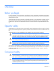
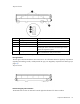
Component identification Structural component identification The HP POD 40c G2 documentation frequently refers to the specific components of the HP POD 40c G2 as shown in the following figure and described in the following table.
• Regulatory compliance identification number—This product has been assigned a unique regulatory model number and is located on the door to the control panel inside the cold aisle of the HP POD 40c G2, as shown in the following figure. • CSC Safety Approval placard—Each HP POD 40c G2 has a CSC Safety Approval placard that includes the model number, serial number, and proof load. The CSC Safety Approval placard is located on the cargo end of the HP POD 40c G2, as shown in the following figure.
Top view shown Item Component Description 1 Exit sign locations Indicates the location of an exit 2 Fire strobe light Indicates a fire alarm condition within the HP POD 40c G2 3 EPO button Disconnects the HP POD 40c G2 from main power feeds 4 Fire alarm manual pull* Enables manual initiation of the fire system, which includes activating the interior and exterior fire strobe lights and the optional fire suppression system 5 Fire suppression abort button* Aborts the fire suppression system.
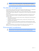
Top view shown Electrical power component identification Front view shown Item Component Description 1 Fire box* Connection location for fire emergency and VESDAnet signals 2 Demarcation box* Customer communication connection point for the following components: • • • 3 415 Y/240 V 3-phase, 4-wire, 800 A electrical panel ECS Security Phone Feed A power for critical IT loads (electrical busways) and house power Component identification 11
Item Component Description 4 415 Y/240 V 3-phase, 4-wire, 800 A electrical panel Feed B power for critical IT loads (electrical busways) and house power *The demarcation box and the fire box are communication data points that are provided on the POD by HP. Connecting these data points is the responsibility of the customer, unless an approved Statement of Work is initiated.
Front view shown Item Electrical safety label Description 1 Input power Lists the input power information 2 Panel schedule/circuit breaker table Lists the layout and designation for all circuit breakers on the panel 3 Fuse type table Lists all fuse type and sizes 4 Wire color code (on page 27) 415Y/240V color codes • • • • • Purple/Brown—Phase A/L1 Purple/Orange—Phase B/L2 Purple/Yellow—Phase 3/L3 Purple/White—Neutral Green and yellow—Equipment ground Component identification 13
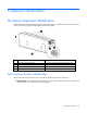
Control cabinet component identification Item Component Description 1 VESDA air sampling smoke detection unit VESDA power supply with battery backup An early warning laser scan smoke detection unit Fire alarm and suppression release control panel • 2 3 Provides power to the VESDA and backup power to the VESDA during a utility power loss • Controls all fire systems within the HP POD 40c G2, including the smoke detection system, fire suppression system, fire pulls, and so on Includes a battery bac
CAUTION: If any racks contain empty RU space, use the HP POD 40c G2 filler panels to maintain the efficiency of the HP POD 40c G2 thermal system. Filler panels are available from HP in 10-pack quantities (part number AQ682A) and 100-pack quantities (part number AS993A). For more information about racks and network cabling, see the HP Performance Optimized Datacenter Networking Guide.
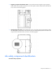
Life safety systems Life safety overview The HP POD 40c G2 has multiple life safety systems that all work together to protect the HP POD 40c G2 equipment and personnel.
The EPO system must be reset before you can power up and restart the HP POD 40c G2. To reset the EPO system: 1. Verify that the key control for the EPO mode is in the Armed position. 2. Press the white EPO Reset button. If you triggered the EPO system manually, you must reset the EPO button that you pressed to the Active position. ECS touchscreen and EPO indicators The ECS touchscreen and EPO indicators are located on the door to the control panel.
Item Component 7 EPO mode Indicator color Key control Description Enables you to select the EPO mode: • • • Armed Test Bypass For more information, see "EPO modes (on page 18)." 8 EPO reset White button Resets the EPO system when pressed EPO modes The EPO system has three operating modes: • Armed—The EPO system is armed and operational. • Test—The EPO system is in test mode and does not initiate during events that normally trigger an EPO.
Manual fire pulls The HP POD 40c G2 includes two fire pulls. One fire pull is located next to the personnel access door and the second fire pull is located next to the emergency exit.
IMPORTANT: The VESDA filter must be changed regularly to ensure accurate smoke detection readings. For more information about changing the VESDA filters, see the HP Performance Optimized Datacenter 40c G2 Maintenance and Service Guide. (Optional) Fire suppression system CAUTION: The POD fire suppression system is manufacturer designed, engineered, and installed to comply with national standards.
Fire suppression sequence of operations After the fire suppression system is activated by a VESDA signal or a manual fire pull, a 30-second countdown begins before the fire suppression agent is released to the HP POD 40c G2 interior through the fire system piping. VESDA initiation Press the fire suppression abort button to interrupt the fire suppression release countdown for 30 seconds.
Power, electrical, and controls Site electrical system To ensure a complete and safe integration of the HP POD solution with your facility, HP requires that you complete the following actions for the installed electrical system prior to the installation of the HP POD solution: • Short circuit analysis • Arc flash study • Circuit breaker coordination study These actions must be performed for all associated parts of the electrical power train.
A certified electrician must test and verify that the HP POD 40c G2 is properly grounded. Lightning protection The HP POD 40c G2 structure and internal components are all bonded together. A common Grounding Electrode Conductor Connection point is provided. Proper bonding and grounding of the HP POD 40c G2 minimizes the effects of a lightning strike. A surge protection device is provided on the HP POD 40c G2 input connection to protect the HP POD 40c G2 electrical system from voltage transients.
Capacities HP POD 40c G2 capacity limitations The capacity limitations for the HP POD 40c G2 are separated into two categories: electrical power and mechanical cooling capacities. Both of these categories are interdependent and must be considered in conjunction with the overall customer requirements. Electrical and mechanical cooling capacities Feature Specification Critical IT electrical connections 2 x 800A feeders at 415Y/240 V, 3-phase, 4-wire, with equipment ground conductors 10.2 x 10.
Top view shown The top of each electrical panel has four 10.16 cm (4 in) welded couplings where the power feeders are connected. Power feeders are sized in accordance with NEC and IEC regulations. Electrical panels WARNING: To avoid the risk of personal injury or loss of life, all personnel must comply with PPE requirements when opening or working inside areas of the HP POD 40c G2 that are marked as hazardous voltage, per NFPA 70E in accordance with NEC (NA) and IEC (EMEA and APJ).
Front view shown Arc flash safety The customer must complete an arc flash assessment of the HP POD 40c G2 and the associated electrical supply system for operation, maintenance, and so on. Power distribution: Electrical busway system The rack power distribution system for the HP POD 40c G2 is protected by electrical circuit breakers located on the end of the HP POD 40c G2.
Feature Specification Frequency 60 Hz Amps (per busway) 200 A Voltage (per busway) 415 V Grounding Copper Busway conductors 3-phase + neutral + equipment ground Panel schedules The panel schedule for each electrical panel is permanently affixed to the inside cabinet door of each electrical panel. Wire color code IMPORTANT: UL-approved colored tape over another color of wire is only acceptable on wire sizes #2 and larger.
Control cabinet power components Item Component 1 VESDA power supply and battery Provides power to the VESDA as well as backup power during a backup power failure 2 Customer connection box Controls and organizes information monitored by the HP POD 40c G2 security components 3 ECS modules and relays Relays for the ECS control, ECS communications, I/O connections and terminal block connections 4 EPO controller board and house panel fuses Connections for the EPO system and fuses for other house pa
Top view shown The HP POD 40c G2 electrical busways can be configured for non-redundant power or redundant power. The HP POD 40c G2 can be installed as a single source 1N load by providing all required feeders from one common power source and from common switchboards and transformers. A 2N redundancy installation is configured by feeding the parallel power paths from independent power sources, switchboards, and transformers.
• Redundant power installation (2N load)—Four busways are powered from one power feed, and the remaining four busways are powered from a different power feed. Drop boxes The internal electrical busways provide a location to connect each of the drop boxes, which then power the PDUs. Stagger the drop boxes on the electrical busways by connecting one drop box to busway #1 and connecting the next drop box to busway #2.
• To disable power to all racks, open the breaker for each busway on the corresponding electrical panel on the HP POD 40c G2 exterior. Power configurations IMPORTANT: Different PDUs can alter the average power capacity per rack.
All emergency lights are tied to the battery backup power, keeping the interior of the HP POD 40c G2 illuminated during a power outage or emergency. For more information about the LED lights, see the HP Performance Optimized Datacenter 40c G2 Maintenance and Service Guide.
Environmental control system Environmental control system overview The ECS developed for the HP water-cooled POD is a stand-alone control system that requires no external connections with an external site system, BMS, public or private Internet sites, cloud, or wireless system to properly control the POD operation. The ECS includes Modbus TCP/IP connections through which a variety of data can be retrieved.
By connecting your HP POD 40c G2 to a BMS system, you can monitor the various parameters and alarms. For more information, see "Navigating the ECS interface (on page 41)." The complete list of parameters and alarms that can be monitored will be discussed with your facilities personnel. IMPORTANT: If your site does not have a BMS, HP POD 40c G2 ECS data can be sent to and viewed from a set IP address. Communication occurs through an Ethernet cable that is connected to the demarcation box (on page 63).
Top view shown Item Sensor Quantity Description 1 Differential pressure sensor probes 12 • 2 Temperature sensors 6 • • Monitors the hot and cold aisle differential pressure and the air filter differential pressure in various locations throughout the HP POD 40c G2 Reports data to the ECS • Monitor the temperature in various locations throughout the cold aisle of the HP POD 40c G2 Reports data to the ECS 3 Humidity sensors 2 • • Monitors humidity for the cold aisle Reports data to the ECS
Heat exchanger temperature sensors There are two contact temperature sensors per heat exchanger. One temperature sensor is located on the inlet supply piping and one temperature sensor is located on the outlet return piping. These sensors measure water temperature and report data to the ECS. Top view shown Facility connections to ECS You can connect your facility to the ECS using the RJ45 located in the demarcation box (on page 63) or cables that are hard-wired through the two 5.
Managing the ECS from the HP POD 40c G2 The ECS interface is viewed directly from the ECS screen on the control cabinet door in the cold aisle. For more information, see "ECS touchscreen and EPO indicators (on page 17)." To access the ECS using a host computer, connect an Ethernet cable between the host computer and the designated ECS jack on the back of the door inside of the control cabinet. Configuring the ECS 1. Connect a host computer to the ECS.
b. Double-click Local Area Connection. c. Select Internet Protocol (TCP/IP). d. Click Properties. e. Select Use the following IP address. f. Enter the new IP address. Be sure to specify an IP address in the same network group as the ECS controller. By default, the ECS controller uses 192.168.20.1. The IP address for your computer can include any number in the group from 2 to 254.
g. Click OK. 3. Click OK to save changes and close the TCP/IP Properties screen. 4. Click OK to close the Local Area Connections Properties screen. Logging in remotely to the ECS Before you can log in remotely, you must do the following: • Add the PLC to a network • Obtain a username and password • Obtain the static IP address of the PLC. For more information, see "Locating the ECS IP addresses (on page 40)." Use the remote desktop application to log in to the ECS remotely: 1.
4. Click Connect. Locating the ECS IP addresses IMPORTANT: The ECS has three NIC addresses: 10.10.10.1, 10.10.10.2, and an IP address that is set up by the customer for external communication. The PLC must be connected to locate the IP address for each NIC. For more information, see "Managing the ECS from the HP POD 40c G2 (on page 37)." To locate the ECS IP address: 1. Select Start>Run. 2. Enter ipconfig. The IP address appears. -or1. Select Start>Network and Sharing Center. 2.
Password protection The ECS has two levels of security: • Customer • Service The following screens are available using the customer-level password: • Overview screen (on page 43) • Status overview screen (on page 45) • Basic System Configuration screen (on page 45) The following screens require the service-level password: CAUTION: Making changes to the ECS in the service-level area can cause the cooling system components to fail.
Item Icon name Description 1 Zone (#) power supply status Navigates directly to the Power Details screen for the specified Zone (#) 2 Fan Bank Output Navigates directly to the Fan Control Detail screen for the specified Zone (#) 3 Enter Password • • Customer-level password—Navigates directly to the Basic System Configuration screen Service-level password—Navigates directly to the Advanced Configuration screen ("Advanced System Configuration screen" on page 49) or Control Settings screen ("Control
Overview screen The Overview screen appears upon activation of and displays an overview of the ECS components and the status of each component. The Overview screen displays the following information. Information Description EPO system status Indicates the status of the EPO system: • • Green—The EPO system is armed and operational. Red—The EPO system is activated.
Information Description Average cooling system performance data Indicates cooling system sensor averages System status Indicates the status of the ECS system: • • Green—All components within the ECS system are operating within normal parameters and no active ECS alarms exist. Red—One or more of the ECS components is indicating an alarm condition.
Status Overview screen The Status Overview screen displays the status of all system component alarms. For more information about the alarms, see "ECS alarms (on page 54)." The ECS component icon colors indicate the component status: • Green—No alarm conditions exist and the component is operating within normal parameters. • Red—An alarm condition for that component exists. Basic System Configuration screen IMPORTANT: The ECS parameters must be set by qualified service personnel only.
The Basic System Configuration screen enables you to configure the basic alarm parameters and the definition of units. The configured parameters are used to trigger an ECS alarm only and do not configure the cooling system.
To configure the cold aisle low temperature alarm parameters: 1. Select Cold Aisle Low Alarm Temperature. A keypad appears. 2. Enter a temperature alarm parameter. 3. Select Save to store the new parameters in the system configuration file. To configure the cold aisle high temperature alarm parameters: 1. Select Cold Aisle High Alarm Temperature. A keypad appears. 2. Enter a temperature alarm parameter. 3. Select Save to store the new parameters in the system configuration file.
To configure the low differential pressure parameters: 1. Select Difference Pressure Low Alarm. A keypad appears. 2. Enter a differential pressure alarm parameter. 3. Select Save to store the new parameters in the system configuration file. To configure the high differential pressure parameters: 1. Select Difference Pressure High Alarm. A keypad appears. 2. Enter a differential pressure alarm parameter. 3. Select Save to store the new parameters in the system configuration file.
To configure the chilled water supply low temperature alarm parameters: 1. Select Chilled Water Supply Low Alarm Temperature. A keypad appears. 2. Enter a temperature alarm parameter. 3. Select Save to store the new parameters in the system configuration file. To configure the chilled water supply high temperature alarm parameters: 1. Select Chilled Water Supply High Alarm Temperature. A keypad appears. 2. Enter a temperature alarm parameter. 3.
The Advanced System Configuration screen displays the static IP address for each power meter, fan controls, and other details about the HP POD 40c G2.
Calibrating the flowmeter This option enables flow rate calibration based on the value of a calibrated flow meter. To calibrate the flowmeter: 1. Power down the HP POD 40c G2. For more information, see "Power down procedure (on page 70)." 2. Select Flowmeter Calibration Factor. A keypad appears 3. Enter the calibration factor. 4. Select OK. 5. Select Save to store the new parameters in the system configuration file.
Enable/disable power management The current power management setting appears on the Enable/disable Power Management button. To enable or disable power management in the ECS: 1. Select Enable/disable Power Management. 2. Select Save to store the new parameters in the system configuration file. Setting the IP address for each power meter The current, preset static IP address appears above the Change IP address button.
To set the HP POD 40c G2 serial number in the ECS: 1. Select POD S/N. A keypad appears. 2. Enter the HP POD 40c G2 serial number. For more information, see "Parts and part number identification (on page 8)." 3. Select Save to store the new parameters in the system configuration file. Controller Settings screen You can only access this screen after you have entered a service-level password. The Controller Settings screen displays the control setpoints for each major system component.
CAUTION: Making changes to the ECS in the service-level area can cause the cooling system components to fail. Only allow authorized, qualified, and trained personnel to change configuration settings in the service-level area of the ECS. You must select Save to store the parameter changes in the system configuration file. If you do not save your changes, the old parameters stored in the configuration file reload when the system starts.
Alarm Meaning Solution EPO The EPO system activates and the HP POD 40c G2 shut down. 1 Differential pressure 2 The difference in pressure 1 between the hot and cold aisles is above the setpoints. 2 Follow the emergency procedures for your facility. After the emergency is cleared, reset the EPO and other HP POD 40c G2 systems. Verify that the cold/hot aisle differential pressures are within the setpoints. Contact HP service if you are still within your service contract.
Cooling system HP POD 40c G2 cooling system theory of operation CAUTION: Using contaminated supply water can cause decreased cooling capacity or disruption in service. The supply water must meet the guidelines stated in the HP Performance Optimized Datacenter 40c G2 Site Preparation and Requirements Guide. Damage caused by contaminated supply water is not covered by the warranty.
The minimum HP server inlet temperature is 10°C (50°F). For non-HP equipment, consult the documentation for that equipment. Water quality requirements and specifications The following are the water quality requirements and specifications: • Closed-loop water must not contain any lime scale deposits or loose debris. • The temperature of the chilled water supplied to the HP POD 40c G2 must be 12ºC to 24ºC (55ºF to 75ºF). CAUTION: Freezing water can cause a blockage and damage to the unit.
Feature Specification Facility input temperature to the HP POD 40c G2 12ºC to 24ºC (55ºF to 75ºF) Working pressure 1,034 kPa (150 psi) HP POD 40c G2 pressure drop 172.4 kPa (25 psi) HP POD 40c G2 water flow rate 908.5 lpm (240 gpm) Chilled water supply and return connections • • North America—Two 10.16 cm (4 in) ASME B16.5 class #150 flanges International—Two DIN PN16 DN100 flanges Cooling system components Each of the six heat exchanger area access hatches are rated NEMA 3R for outdoor use.
Side view shown Item Component Description 1 Heat exchanger Use chilled facility water to cool the air in the HP POD 40c G2 2 Drain pan sensor Detects excessive amounts of condensate in the drain pan and sends an alarm signal to the ECS 3 Drain pan Collects and directs heat exchanger condensate to the condensate drain 4 Condensation drain Removes condensation from the drain tray to the exterior of the HP POD 40c G2 5 Header drain pan Provides leak detection for the chilled water supply and
Depending on the IT equipment you have installed in your HP POD 40c G2, you can choose to change both default parameters to improve the overall efficiency of your system. To discuss the effects of changing these parameters for your specific HP POD 40c G2, contact HP ("HP contact information" on page 75).
The HP POD 40c G2 has two heat exchanger condensate drains. IMPORTANT: You might need to connect the HP POD 40c G2 drain directly to the local storm or sanitary drain, depending on the local jurisdiction. If your HP POD 40c G2 is located indoors, you can connect to an external drain line. If your HP POD 40c G2 is located outdoors, the drained water drains out the back of the HP POD 40c G2.
IT networking and communications Networking Connecting the HP POD 40c G2 to the facility network is a vital part of ensuring the functionality of the various communication systems. See the HP Performance Optimized Datacenter Networking Guide for more information. All connections are the responsibility of the customer. For configuration and installation instructions, consult with HP. Connection portals There are networking and connection portals located on the top of the utility-end of the HP POD 40c G2.
Connection portal diameter Connection point 5.08 cm (2 in) portal Communication connection 2 for all communication • • • • Quantity ECS EPO Fire alarm Telephone Demarcation box The following communication connections between the customer facility and the HP POD 40c G2 are made through the demarcation box: • ECS communication • Security communication • Telephone End view shown You must make the connections between the facility and the HP POD 40c G2.
End view shown You must make the connections between the facility and the HP POD 40c G2. For configuration and installation instructions, consult with HP.
Optional components Fire protection system The fire protection system is a HP POD 40c G2 self-contained system, with no connection to your ECS. The fire protection system consists of 3M Novec 1230, a clean agent fire suppressant, eliminating the need for additional water to be connected to the HP POD 40c G2 in case of a fire emergency. Humidifier The humidifier option maintains the humidity within the HP POD 40c G2 within a set range, according to ASHRAE standards.
Power up procedure Standard HP POD 40c G2 power up procedure This procedure is for your reference only and assumes that the POD was fully commissioned and powered up by HP before being turned over to you. Before beginning the power up procedures in this section, verify that the POD is not in operation and that the internal ambient temperature of the POD is greater than 10ºC (50ºF).
Site electrical Close all POD site power feeder breakers and monitor for any effects that are not standard. Site chilled water 1. Open the POD supply chilled water isolation valve. 2. If necessary, vent the air from the chilled water return header. 3. Open the POD return chilled water isolation valve. 4. Verify that audible flow noises are present. ECS and EPO Verify the following on using the ECS touchscreen and EPO indicators: • The ECS panel is operational and displays the user interface.
This process ensures personnel safety during the electrical start up of the HP POD 40c G2. WARNING: To avoid risk of personal injury or loss of life, do not open an energized POD electrical cabinet without an energized work permit and appropriate PPE. Cold weather power up checklist Site electrical Verify that all POD site power feeder breakers are open. POD electrical • Hot aisle Verify that all IT power drop box breakers located on the power tap boxes are open. • Cold aisle a.
IMPORTANT: To allow the POD ambient temperature to be raised in a controlled manner, open the chilled water supply and return isolation valves to enable 908.49 lpm (240 gpm) at a temperature of 13ºC to 24ºC (55ºF to 75ºF) to flow through the heat exchangers and allow the circulation fans to bring the ambient temperature to >10ºC (50ºF). • Portable heaters can be used to uniformly disperse supplemental heat throughout the POD. • Electric portable heaters must be powered from an outside source.
Power down procedure 1. Power down all IT equipment. 2. Open all POD power drop box breakers. 3. Monitor the system parameters and allow the POD to cool to an acceptable temperature. Be sure that the cold aisle temperature does not fall below 10°C (50°F.) 4. Close the POD return chilled water isolation valve. 5. Close the POD supply chilled water isolation valve. 6. Open the POD main power feed breakers. 7. Unlock the POD power cabinets A and B. 8.
Specifications General HP POD 40c G2 specifications Features Specifications Overall dimensions • • • Weight1 Empty—16,783 kg (37,000 lb) Maximum fully loaded—46,266 kg (102,000 lb) Maximum power2 600 kW HP POD 40c G2 Power input voltage 380 VAC to 415 VAC Power distribution3 8 x 200 A electrical busways Maximum rack quantity 20 racks Rack Units (RU) per rack 50 RU Rack Units (RU) total 1000 RU Average capacity per rack (kW) 30 kW Peak rack capacity 69 kW Voltage to rack 200 VAC to 240
Fire alarm panel connections The electrical layout of the fire alarm system is as described in the schematic drawing supplied with the HP POD 40c G2. Water specifications The following table describes the chilled water system specifications for the HP POD 40c G2. Feature Specification Facility input temperature to the HP POD 40c G2 12ºC to 24ºC (55ºF to 75ºF) Working pressure 1,034 kPa (150 psi) HP POD 40c G2 pressure drop 172.4 kPa (25 psi) HP POD 40c G2 water flow rate 908.
Feature Specification Non-operating temperature* -29ºC to 54ºC (-20ºF to 130ºF) Operating humidity • • 0% to 100% external 10% to 90% non-condensing internal Non-operating humidity* • • 5% to 95% relative non-condensing 39ºC (102ºF) maximum wet bulb temperature Operating altitude -76.2 m to 3,048 m (-250 ft to 10,000 ft) Non-operating altitude -76.
Maintenance Periodic maintenance Perform periodic inspections to ensure that the HP POD 40c G2 continues to perform according to design parameters. During periodic inspections, pay special attention to electrical connections and wiring. For more specific maintenance information, see the HP Performance Optimized Datacenter 40c G2 Maintenance and Service Guide. Sample HP POD 40c G2 maintenance schedule For detailed maintenance information and schedules, consult with HP services.
Contacting HP Before you contact HP Be sure to have the following information available before you call HP: • Active Health System log Download and have available an Active Health System log for 3 days before the failure was detected. For more information, see the HP iLO 4 User Guide or HP Intelligent Provisioning User Guide on the HP website (http://www.hp.com/go/ilo/docs).
Regulatory compliance notices HP POD 40c G2 regulatory compliance The HP POD 40c G2 complies with the following regulatory standards.
• The HP POD 40c G2 meets the following ratings: Feature Specification Category Rated Overvoltage Category III Protection Surge protection device Class Class1 Ambient temperature 2°C to 54°C (35.6°F to 129.2°F) Relative humidity 0% to 100% humidity • As part of the overall certification, relevant sections of the International Building Code have been applied as part of the design and evaluation. The current design supports wind loads up to 90 mph.
Regulatory requirements for EXIT signs Manufacturers of tritium EXIT signs are “specific licensees,” meaning they are licensed by the NRC or an Agreement State. The signs are considered “generally licensed devices,” because they are inherently safe enough to be handled or used by anyone with no radiation training or experience.
Glossary AHJ authority having jurisdiction branch circuit The conductors and components following the last overcurrent protective device protecting a load. control circuit A circuit that carries the electric signals directing the performance of a controller, and which does not carry the main power circuit. control transformer A transformer whose secondary supplies power to control circuit devices only (excluding loads). cover An unhinged portion of an enclosure that covers an opening.
equipment A general term, including fittings, devices, appliances, luminaires, apparatus, machinery, and the like used as a part of, or in connection with, a modular data center. (Source: NEC.) fuse, branch circuit type A fuse of Class CC, G, H, J, K, L, R, and T. These fuses are able to provide branch circuit protection. fuse, supplementary type Miscellaneous type and miniature type fuses. These fuses are able to provide supplementary protection only.
UPS uninterruptible power system Glossary 81
Documentation feedback HP is committed to providing documentation that meets your needs. To help us improve the documentation, send any errors, suggestions, or comments to Documentation Feedback (mailto:docsfeedback@hp.com). Include the document title and part number, version number, or the URL when submitting your feedback.
Index A access 65 alarms, ECS 54 B basic system configuration 45 before you begin 6 before you contact HP 75 buttons 8 C cables, FCC compliance 77 Canadian notices 77 chilled water pressure, calibrating 51 cold weather startup 67 communication connections 63 component health 6 components 8 components, identification 8 condensation management 60 connectors 8 considerations, environmental 7 contact information 75 control cabinet components 14 controller settings 53 controls 22 cooling 56 cooling the HP POD
life safety systems 16 lightning protection 23 locating the ECS IP address 40 logging in to ECS 39 M maintenance 74 maintenance schedule 74 modifications, FCC notice 77 N specifications, rack 72 specifications, water 72 Starline 26, 28 start up procedure 66 structural components 8 system components 8 T temperature, water 56 theory of operation 56 thermal air flow performance 72 navigating the ECS interface 41 U O using ECS 33 using the ECS 33 operator safety 6 optional components 65 overview screen