
User Manual
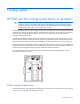

Cooling system 60
Depending on the IT equipment you have installed in your HP POD 40c G2, you can choose to change both
default parameters to improve the overall efficiency of your system. To discuss the effects of changing these
parameters for your specific HP POD 40c G2, contact HP ("HP contact information" on page 75).
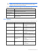
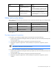
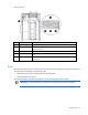
Item Sensor Quantity Description
1
Fans 3 banks of 6
(18 total) fans
per zone
Circulates cool air from the heat exchangers
throughout the HP POD 40c G2
2
Fan power supply assembly 6 Provides power for the fans
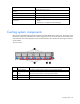
Condensation management
CAUTION: To maintain accurate environmental conditions inside the HP POD 40c G2, do not
leave the HP POD 40c G2 doors open during operation.
The heat exchanger drip pans collect any condensation that forms on the heat exchangers. The collected
condensate drains out of the HP POD 40c G2 through the heat exchanger condensate drains. HP
recommends connecting the condensate drains on the HP POD 40c G2 to a facility drain to prevent
collection of water near the HP POD 40c G2.
The HP POD 40c G2 has two 3.175 cm (1.25 in) condensate drain outlets, one located at each end of the
hot aisle of the HP POD 40c G2 directly connected to the heat exchanger drip pans. The HP POD 40c G2
has two drains for the water main supply and return lines located on the front of the POD.
To avoid excessive buildup of condensate and to conserve energy, raise the cooling water temperature to
above the dew point to manage condensation while maintaining the necessary cooling capacity.
Drains
WARNING: Water that drains around the HP POD 40c G2 can cause a potential slip hazard.
Use caution where slip hazards are present.
Water from natural condensation will form. Condensation from the heat exchangers flows to the
condensation drains at each end of the HP POD 40c G2.