HP PDR Management Module User Guide Part Number 484051-003 October 2009 (Third Edition)
© Copyright 2008, 2009 Hewlett-Packard Development Company, L.P. The information contained herein is subject to change without notice. The only warranties for HP products and services are set forth in the express warranty statements accompanying such products and services. Nothing herein should be construed as constituting an additional warranty. HP shall not be liable for technical or editorial errors or omissions contained herein. Confidential computer software.
Contents Overview..................................................................................................................................... 6 Introduction .............................................................................................................................................. 6 Features ................................................................................................................................................... 6 Web interface requirements................
Terminal emulation session ............................................................................................................. 50 POST ..................................................................................................................................................... 50 Navigating the menus.............................................................................................................................. 50 Service Menu....................................................
Updating the firmware ................................................................................................................ 72 Updating the firmware overview................................................................................................................ 72 Acronyms and abbreviations........................................................................................................ 73 Index........................................................................................
Overview Introduction The HP PDR Management Module enables you to monitor and manage environments of PDRs through the serial and network connectors located on the front of the management module. The management module can be configured to send alert traps to HP Systems Insight Manager and other SNMP management programs or used as a stand-alone management system.
Software Browser HP-UX operating system (32-bit only) • Monitor resolution Mozilla 1.6.
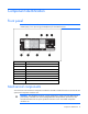
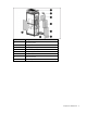
Component identification Front panel NOTE: This module is used for both the PDR and the UPS. For use in the PDR, see the HP website (http://www.hp.com/go/rackandpower) for the latest firmware.
Callout Description 1 Rack access panel 2 Management module card 3 LCD display panel (2) 4 Circuit breaker panel (2) 5 Base panel (2) 6 Floor panel (2) 7 Knockout panel (2) 8 Side access panel Component identification 9
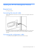
Installing the HP PDR Management Module Required tools No. 2 Phillips screwdriver Connecting the network cable Connect a standard Ethernet cable between the network connector on the management module and a network jack. This connection is used to access the management module remotely through telnet or the web interface. The management module also uses the network connection to facilitate ModBus and SNMP-based monitoring. Connecting the configuration cable 1.
2. Connect one end of an RJ-45 cable to the RJ-45 connector on the adapter. 3. Connect the other end of the RJ-45 cable to the Config/Pass-Thru connector on the management module. This connection is used to configure and access the management module locally through a terminal emulation program.
2. Enter a description, select an icon for the connection, and then click OK. The Connect To window appears. 3. Select the serial connector on the host computer to which the DB-9 to RJ-45 adapter is attached, and then click OK. The COM Properties window appears. 4. Select the following parameter values, and then click OK. o Bits per second—115200 o Data bits—8 o Parity—None o Stop bits—1 o Flow control—None Configuring the management module for remote access 1.
NOTE: If your network is configured with a BOOTP server, the network settings are automatically assigned. Verify and note the assigned values. 5. If your network is not configured with a BOOTP server: a. On the Main menu, enter 1 at the prompt to open Module Configuration submenu. b. Enter 2 at the prompt to enter the Network Configuration submenu. c. Enter 1 at the prompt to enter the Network Settings submenu. 6. From this menu, change the mode used to acquire a network IP address to Static IP.
HP PDR Management Module web interface Accessing the web interface You can access the web interface remotely through a Web browser (on page 14). Web browser Use a web browser to access the HP PDR Management Module web interface: 1. If necessary, configure the management module by: a. Launching a terminal emulation program (on page 11). b. Configuring the management module for remote access (on page 12). 2.
For instructions on changing the password, see "My Account menu (on page 33)." Admin session logins, logouts, and terminations are recorded in the Event Log menu (on page 30). The console session timeout length can be modified in the Remote Access tab (on page 41). The following is a list of recommended password guidelines. • Passwords should not be shared with others. • Passwords should be limited to one or two people, if shared with others.
• The certificate is untrusted, meaning it was signed by a certifying authority that is unknown to your browser. • The certificate has expired or is not yet valid. This condition can occur if you issue your own certificate and it has expired. • The name on the certificate does not match the name of the site in the browser address field. For more information about security considerations, see "Security considerations overview (on page 68).
3. Perform any other steps necessary to verify the identity of the management module. 4. After verifying the management module, do one of the following: a. Click either Accept this certificate permanently or Accept this certificate temporarily for this session. b. Click OK. NOTE: If using Mozilla or SeaMonkey, you can manually import the file into the browser by clicking Edit>Preferences>Privacy & Security>Certificates>Manage Certificates>Authorities>Import.
o • The legend displays the meaning of symbols used in the interface. Expand and collapse the legend by clicking the arrow in the upper right corner.
The following screen shows an example of the overall PDR status for the North American model. The following screen shows an example of the overall PDR status for the International model NOTE: The current rating is 200 A for the International model.
Click Help to view online help. Click the PDR Breakers (Panel 1) or PDR Breakers (Panel 2) tab to display the current power and the load percent for each position.
The following screen shows an example of the information available for the PDR Breakers (Panel 1) International model.
The following screen shows an example of the information available for the PDR Breakers (Panel 2). Click Help to view online help. Alarms menu Click Alarms in the left navigation frame to display the Alarms screen. This screen displays the alarms for the PDR. The alarms are listed in alphabetical order. Each entry includes a description and the date and time at which the alarm most recently occurred.
For a complete list of PDR alarms, see "PDR alarms (on page 23)." Click Refresh to refresh the screen, or click Help to view online help.
Alarm number Alarm name 9 OUTPUT_AC_OVER_VOLTAGE 10 OUTPUT_AC_UNDER_VOLTAGE 11 OUTPUT_UNDER_OVER_FREQUENCY 12 REMOTE_EMERGENCY_POWER_OFF 16 BUILDING_ALARM_4 17 BUILDING_ALARM_3 18 BUILDING_ALARM_2 19 BUILDING_ALARM_1 25 OUTPUT_OVERLOAD 50 OUTPUT_CURRENT_OVER_100PERCENT 53 EEPROM_FAULT 63 INTERNAL_COMMUNICATION_FAILURE 90 INPUT_PHASE_ROTATION_ERROR 97 EMERGENCY_SHUTDOWN_COMMAND 159 LEVEL_2_OVERLOAD_PHASE_A 160 LEVEL_2_OVERLOAD_PHASE_B 161 LEVEL_2_OVERLOAD_PHASE_C 162 LEVE
Alarm number Alarm name 272 NEUTRAL_OVERLOAD_WARNING 273 NEUTRAL_OVERLOAD 274 GROUND_CURRENT_WARNING 275 GROUND_CURRENT_OVERLOAD 276 INPUT_VOLTAGE_THD_WARNING_L1 277 INPUT_VOLTAGE_THD_WARNING_L2 278 INPUT_VOLTAGE_THD_WARNING_L3 279 INPUT_CURRENT_THD_WARNING_L1 280 INPUT_CURRENT_THD_WARNING_L2 281 INPUT_CURRENT_THD_WARNING_L3 282 OUTPUT_VOLTAGE_THD_WARNING_L1 283 OUTPUT_VOLTAGE_THD_WARNING_L2 284 OUTPUT_VOLTAGE_THD_WARNING_L3 285 OUTPUT_CURRENT_THD_WARNING_L1 286 OUTPUT_CURRENT
Click the Management Module tab to display contact information and specific device information about the management module. Click the PDR tab to display specific device information about the PDR. Enter the system name and contact information using the System Information tab (on page 37) on the Network Management screen. Click Refresh to refresh the screen, or click Help to view online help. Parameters menu Click Parameters in the left navigation frame to display the Parameters screen.
Click the PDR Input & Output tab to display the input and output current and voltage per phase. Click the PDR Thresholds tab to display the Panel 1 and 2 percentage of load in warning and critical status. This tab also displays the breaker (Panel 1 and 2) positions, phase, percentage of load in warning and critical status.
This screen shows an example of the information available for the North American model.
This screen shows an example of the information available for the International model. Click Refresh to refresh the screen, or click Help to view online help.
Event Log menu Click Event Log in the left navigation frame to display the Event Log screen. This screen displays a log of the events that have occurred on the PDR.
NOTE: When the log reaches the maximum of 500 entries, new entries overwrite the oldest entries in the log. On the Event Log screen: • Click Download Event Log to export the event log. The File Download screen appears. o Click Open to view the log in a user-selected application. o Click Save to save the log file (.csv) to your computer. • Click Clear Event Log to clear the log files. • Click Help to view online help.
The following information is displayed for each application event: • User—The login name of the user who performed the action • Event—A description of the application event • Date—The date at which the event occurred • Time—The time at which the event occurred NOTE: When the log reaches the maximum of 500 entries, new entries overwrite the oldest entries in the log. On the Application Log screen: • Click Download Application Log to export the application log. The File Download screen appears.
My Account menu Click My Account in the left navigation frame to display the My Account screen. This screen enables you to change your login password. To change your password: 1. Enter the new password in the Password field. 2. Enter the new password again in the Verify Password field. 3. Do one of the following: o Click Save Settings to save the new password. o Click Undo Changes to undo the changes. o Click Help to view online help.
User Accounts menu Click User Accounts in the left navigation frame to access the User Accounts screen. This screen enables administrators to manage user accounts. On the User Accounts screen: • Click Undo Changes to undo the changes. • Click Help to view online help. To add a user account: 1. Enter the user's sign-in name in the Sign In Name field. 2. Enter the user's password in the Password field. 3. Enter the user's password again in the Verify Password field. 4.
To delete a user account: 1. Select the Delete checkbox for the user account that is to be removed. 2. Click Delete Users to delete the user account. The account is removed and no longer appears on the User Accounts screen. Network menu Click Network in the left navigation frame to access the Network screen. This screen enables administrators to configure network settings for the management module. The management module MAC address is displayed on the Network screen for informational purposes.
d. Enter the number of hours that should pass between each date and time update. 7. If you disabled NTP in step 5: a. Enter the date. b. Enter the time. c. 8. Select the date format from the dropdown box. Select the Disable radio button if daylight saving time should not be reflected in the time on the management module. -orSelect the Enable radio button to configure time adjustment for daylight saving time: a. Enter the month, day, week, and time for which daylight saving time should start. b.
System Information tab This screen enables administrators to enter contact information for the management module. The information entered on this screen appears on the Identification screen ("Identification menu" on page 25). To configure system information: 1. Enter the name of the management module in the System Name field. This name appears throughout the interface application and is used in SNMP traps. Use a unique name for each management module. 2.
Trap Receivers tab This screen enables administrators to enter information for servers that should receive SNMP traps from the management module. To configure which servers should receive traps: 1. Enable SNMP traps for up to 10 servers. 2. Enter the IP address for up to 10 trap recipients in the IP Address field. 3. Enter the community string for each trap recipient. 4. Do one of the following: 5. o Click Save Settings to save the information. o Click Undo Changes to undo the changes.
2. Enter the IP address for each SNMP manager in the IP Address field. NOTE: SNMP managers cannot communicate with the management module until the IP address is entered on the SNMP Managers screen. 3. Enter the Read community string for each SNMP manager. 4. Enter the Write community string for each SNMP manager. 5. Configure the access type for each SNMP manager. 6. o RO—Read Only o RW—Read/Write Do one of the following: o Click Save Settings to save the information.
5. Click Send Test Email to send a test email. Event Notifications tab This screen enables administrators to define the event notifications, emails, or SNMP traps the management module sends for each event. To configure the event notifications: 1. For each event description listed, select the Enabled checkbox to indicate that email notifications or SNMP traps are sent for that event. To enable all events, click the Email checkbox and the SNMP Trap checkbox at the top of each column. 2.
Remote Access tab This screen enables administrators to enter information for remote access to the management module. To configure remote access: 1. Configure web access by doing one of the following: o Select Disable to disable web access. o Select Enable for HTTP Port and enter the port number to use HTTP. o Select Enable for HTTPS Port and enter the port number to use HTTPS. o Upload the SSL certificate: i. Open the SSL certificate file with a text editor. ii. Select all content. iii.
5. Do one of the following: o Click Save Settings to save the information. o Click Undo Changes to undo the changes. o Click Help to view online help. ModBus menu Click ModBus in the left navigation frame to access the ModBus screen. This screen enables address selection for the ModBus RTU or TCP and the PDR. To configure ModBus: • Configure RTU (serial port communication) a. Select the ModBus/RTU checkbox. b. Enter the device address. If you have one PDR system, the Device Address is 1.
ModBus registers If trying to query the PDR management module, list out the following menu to be queried. The ModBus Register address is based on offset -1. Use function code 04h to read the analog input registers.
Register Name Panel Breaker Count Format Units 1497 Panel Status 1 - 1 UNIT16 - 1498 Panel Voltage 1 RMS 1 - 1 UNIT16 0.1 RMS V 1499 Panel Voltage 2 RMS 1 - 1 UNIT16 0.1 RMS V 1500 Panel Voltage 3 RMS 1 - 1 UNIT16 0.1 RMS V 1501 Panel Frequency 1 - 1 UNIT16 0.1 Hz 1502 Panel Current 1 RMS 1 - 1 UNIT16 0.1 RMS A 1503 Panel Current 2 RMS 1 - 1 UNIT16 0.1 RMS A 1504 Panel Current 3 RMS 1 - 1 UNIT16 0.1 RMS A 1505 Panel Load 1 1 - 1 UNIT16 0.
Register Name Panel Breaker Count Format Units 2745 Breaker 212.42 2 1-42 840 UNIT16 0.01 WS ModBus alarm registers Use function code 02h to read the discrete input contacts (alarm status).
Register Name Count 1033 Invalid Board ID 1 1034 Output KW Overload 1 1035 Xfrmr Ot Warning 1 1036 High Input Thd L1 1 1037 High Input Thd L2 1 1038 High Input Thd L3 1 1039 High Output Thd L1 1 1040 High Output Thd L2 1 1041 High Output Thd L3 1 1042 Neutral Overload Warning 1 1043 Neutral Overload 1 1044 Ground Current Warning 1 1045 Ground Current Overload 1 1046 Input Voltage Thd Warning L1 1 1047 Input Voltage Thd Warning L2 1 1048 Input Voltage Thd Warn
Help tab Menu options listed under the Help tab include: • About menu (on page 47) • Contents menu (on page 48) • Info & Updates menu (on page 48) About menu Click About in the left navigation frame to display the About screen. This screen displays the hardware version, the firmware version, and the MAC address for the management module, as well as a link to the HP website.
Contents menu Click Contents in the left navigation frame to display the Contents screen. This screen provides a list of the links to help topics. Info & Updates menu Click Info & Updates in the left navigation frame to open the HP website.
HP PDR Management Module Service Menu HP PDR Management Module Service Menu overview The HP PDR Management Module Service Menu provides an alternative, limited interface to the management module when the web interface is disabled or not preferred. The menu structure textually displays various measurements and warning and alarm messages from the management module. Also, system values and power fail settings can be configured through the Service Menu and sent to the management module.
Terminal emulation session Use a terminal emulation program to access the HP PDR Management Module Service Menu: 1. Be sure that you have connected the configuration cable to the management module and the host computer. 2. Launch a terminal emulation program, such as HyperTerminal ("Launching a terminal emulation program" on page 11). 3. On the session screen, the POST executes, and then a prompt appears. Press any key within 5 seconds to enter the HP PDR Management Module Service Menu.
Service Menu This menu only appears when accessing the management module using a terminal emulation program.
Output Type Output Panel 2 Load 0, 0, 0 (normal < 100 %) Network Configuration submenu Option number Submenu Description 1 Network Settings Enables you to enter or change network properties for the management module 2 Remote Console Enables you to enter or change parameters for telnet access 3 Web Access Enables you to enter or change parameters for web interface access 4 File Transfer (FTP) Enables or disables the FTP service 5 SNMP Enables you to configure SNMP managers and SNMP traps
Web Access submenu Option number Submenu Description 1 Protocol Selection Enables you to select HTTP or HTTPS 2 HTTP/HTTPS Configuration Enables you to configure the port for HTTP or HTTPS 0 Previous Menu Returns to the previous menu Option number Submenu Description 1 SNMP Managers (NMS) Enables you to select an entry to configure the SNMP managers (computers that use the HP Power MIB to request information from the management module) 2 SNMP Traps Enables you to select an entry to confi
Emails submenu Option number Submenu Description 1 Change SMTP Settings Enables you to enter or change SMTP settings in the SMTP Settings submenu (on page 54) 2 Edit An Entry Enables you to edit an email recipient entry on the Email Recipient submenu (on page 54) 0 Previous Menu Returns to the previous menu SMTP Settings submenu Option number Submenu Description 1 SMTP Server Enables you to enter or change the mail server IP address 2 Sender Email Enables you to enter or change the email
ModBus Configuration submenu Option number Submenu Description 1 ModBus Protocol Selection Allows selection of ModBus protocol 2 Device Address Allows selection of device address 0 Previous Menu Returns to the previous menu ModBus Protocol Selection submenu Option number Submenu Description 1 ModBus/RTU Allows communication from a serial port 2 ModBus/TCP Allows communication from a network port 4 None - 0 Previous Menu Returns to the previous menu Option number Submenu Descript
Option number Submenu Description 2 Secondary NTP Server Enables you to enter or change the IP address of the secondary NTP server 3 GMT Offset (time zone) Enables you to select the time zone from the table provided 4 Update Frequency (1–8760 hours) Enables you to enter the number of hours that should pass between each date and time update 5 NTP Client Enables you to enable or disable the NTP client 6 Accept Changes Enables you to save all changes 0 Previous Menu Returns to the previous
Troubleshooting Browser does not display the web interface for an installed management module Action: 1. Be sure that the IP address and port number are correct. The default port number for non-secure browser connection is port 80. The default port number for secure SSL browser connection is 443. 2. Be sure that the web interface (HTTP/HTTPS) is enabled on the management module. 3. Be sure that the port you are configuring from the management module is not in use.
-or- • Click Continue to this website (not recommended) to ignore the security warning. Error LED illuminates or flashes Action: Press the Reset button on the management module front panel. If the problem persists, contact an authorized service provider. The following table lists the error conditions associated with the management module LED.
Action: Be sure that the breaker rating in the configuration menu matches the actual breaker rating. Non-admin users cannot log in through telnet Possible Cause: A user account was added, but the password was not set. Action: An administrator must edit the user account to set a password. Unable to obtain a valid network address error message displays Possible Cause: • The management module is unable to connect to the BOOTP server. • The MAC address for the management module is not in the BOOTP server.
Technical support Before you contact HP Be sure to have the following information available before you call HP: • Technical support registration number (if applicable) • Product serial number • Product model name and number • Product identification number • Applicable error messages • Add-on boards or hardware • Third-party hardware or software • Operating system type and revision level HP Power Distribution Rack support and contact information CAUTION: To reduce the risk of personal injury
Regulatory compliance notices Regulatory compliance identification numbers For the purpose of regulatory compliance certifications and identification, this product has been assigned a unique regulatory model number. The regulatory model number can be found on the product nameplate label, along with all required approval markings and information. When requesting compliance information for this product, always refer to this regulatory model number.
to radio communications. However, there is no guarantee that interference will not occur in a particular installation. If this equipment does cause harmful interference to radio or television reception, which can be determined by turning the equipment off and on, the user is encouraged to try to correct the interference by one or more of the following measures: • Reorient or relocate the receiving antenna. • Increase the separation between the equipment and receiver.
Class B equipment This Class B digital apparatus meets all requirements of the Canadian Interference-Causing Equipment Regulations. Cet appareil numérique de la classe B respecte toutes les exigences du Règlement sur le matériel brouilleur du Canada.
Japanese notice BSMI notice Regulatory compliance notices 64
Systems Insight Manager integration Systems Insight Manager overview Use HP Systems Insight Manager to: • Discover management modules. As part of the discovery process, HP SIM can detect an installed management module. The web interface for the discovered module can be launched from the HP SIM All Systems page. • Receive SNMP traps from the management module. The module can send event-based traps to HP SIM that include a URL in the trap.
Discovering the management module HP SIM automatically detects management modules as part of the device discovery process. If detected, a hyperlink is included on the HP SIM All Systems page for the PDR on which the management module is installed. The management module should be installed and running before attempting discovery through HP SIM. If the defaults are not used, a new entry can be made to the additionalwsdisc.
To register the MIB: 1. Copy the MIB to the HP\Systems Insight Manager\mibs folder. 2. From the HP\Systems Insight Manager\mibs folder, run mcompile cpqpower.mib from the command line to compile the new MIB. A new file named cpqpower.cfg is created. 3. Register the new MIB by entering mxmib -a cpqpower.cfg from the HP\Systems Insight Manager\mibs command line. 4. Enter HP\Systems Insight Manager\mibs>mxmib at the command line and verify that the new MIB is listed.
Security considerations Security considerations overview The management module implements strict security for two important reasons: • The module manages devices that have the potential to perform operations that are sensitive and destructive. • The management module has browser accessibility.
Optional PDR monitoring using SNMP PDR monitoring Power status, events, and traps can be monitored using third-party SNMP managers. SNMP monitoring supports the HP Power MIB (CPQPOWER.MIB). Using the SNMP submenu (on page 53): 1. Configure the third-party SNMP manager to monitor the HP PDR Management Module. 2. In the third-party SNMP manager, configure the HP PDR Management Module information to be monitored by the SNMP manager. The HP Power MIB (CPQPOWER.
HP PDR Management Module quick setup Quick setup information The HP PDR Management Module has one configuration port, one ModBus port, and one Ethernet port. The quick setup can be done through the Service Menu (on page 51) or online Network Setup. • To access the Service Menu, use HyperTerminal with a serial connection. • To access online Network Setup, use a web browser if the assigned IP address is known.
Accessing the online application with a known IP address 1. Open a browser window. 2. Enter HTTP://xxx.xxx.xxx.xxx, and login to the PDR Management Module application.
Updating the firmware Updating the firmware overview To update the management module firmware from an application, download the HP PDR Management Upgrade Utility on the HP website (http://www.hp.com/go/rackandpower), and follow the attached instructions. If the firmware is corrupted and updates using the HP PDR Management Upgrade Utility are prevented, you can update the firmware using the bootloader. This process is only available when the application is damaged.
Acronyms and abbreviations BOOTP Bootstrap Protocol DHCP Dynamic Host Configuration Protocol DMA direct memory access DRAM dynamic random access memory EEPROM electrical erasable programmable read only memory FTP file transfer protocol HTTP hypertext transfer protocol HTTPS hypertext transfer protocol secure sockets I/O input/output iLO Integrated Lights-Out IP Internet Protocol IRQ interrupt request Acronyms and abbreviations 73
LED light-emitting diode NTP network time protocol PDR power distribution rack POST Power-On Self Test RAM random access memory RMS root-mean-square RTU remote terminal unit SIM Systems Insight Manager SMTP Simple Mail Transfer Protocol SNMP Simple Network Management Protocol SSL Secure Sockets Layer TCP Transmission Control Protocol TFTP Trivial File Transfer Protocol UPS uninterruptible power system Acronyms and abbreviations 74
Index A About menu 47 accessing software, browser 14 accessing the application 71 adding new users 34 alarm conditions 23 Alarms menu 22 alert messages 23 alerts, event notification 40 alerts, viewing 22 Application Log menu 31 B baud rate 11 BOOTP, configuring 70 browser requirements 6 browser security alert 15 browser, launching 14 browser, troubleshooting 57 BSMI notice 64 C Canadian notice 62 changing the IP address 70 class A equipment 61 class B equipment 61 components 8 components, mechanical 8 con
introduction 6 IP address, viewing 25 J Japanese notice 64 L LED, error 8 LED, power 8 LEDs, location 8 LEDs, troubleshooting 57 log files 30, 31 logging in, through a browser 14 Logs tab 29 M MAC address, viewing 25, 35, 47 mail server, setting up 39 management module components 8 management module, discovering 66 Manual Date/Time submenu 56 mechanical components 8 ModBus alarm registers 45 ModBus Configuration submenu 55 ModBus menu 42 ModBus Protocol Selection submenu 55 ModBus registers 43 modificati
static IP addresses 70 System Configuration submenu 55 System Information tab 37 system status 18 Systems Insight Manager, overview 65 T telnet session 49 telnet, using 49 terminal emulation, serial session viewer 50 terminal emulator session 11, 50 time and date, setting 56 tools 10 Trap Receivers tab 38 troubleshooting 57, 60 U updating the firmware 72 User Accounts menu 34 User Accounts submenu 56 W Web Access submenu 53 web interface requirements 6 web interface, accessing 14 web interface, logging i