333644-001.book Page 1 Thursday, July 10, 2003 2:56 PM 4 Drives Caring for Drives Drives are fragile notebook components that must be handled with care. The following cautions apply to all drives. Additional cautions are included with the procedures to which they apply.
333644-001.book Page 2 Thursday, July 10, 2003 2:56 PM Drives Ä■ CAUTION: To prevent loss or damage to the notebook or a drive: ■ ■ ■ ■ ■ ■ Handle a drive carefully. Do not drop it. Excessive force can damage drive connectors. When you insert a drive, use only enough force to seat the drive. Do not spray a drive with cleaning fluid or other liquid or expose it to temperature extremes. Do not remove the primary hard drive (the hard drive in the hard drive bay) except for repair or replacement.
33644-001.book Page 3 Thursday, July 10, 2003 2:56 PM Drives Adding a Drive to the System Removable drives enable you to store and access data. ■ A standard drive can be added to the system by inserting the drive into the notebook MultiBay or optional Advanced Port Replicator. ■ A diskette drive can also be added. ■ A USB drive can be added by connecting the drive to a USB connector on the notebook or optional Port Replicator.
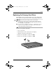
333644-001.book Page 4 Thursday, July 10, 2003 2:56 PM Drives Hard Drive This section discusses the primary hard drive of the notebook. Identifying the Hard Drive Activity Light The hard drive activity light turns on when the primary hard drive is being accessed.
333644-001.book Page 5 Thursday, July 10, 2003 2:56 PM Drives Replacing the Primary Hard Drive The hard drive that is in the hard drive bay is the primary hard drive. Remove it only after the notebook is properly shut down. Ä■ CAUTION: To prevent system lockup and loss of information: ■ Shut down the notebook before removing the hard drive from the hard drive bay. Do not remove the hard drive while the notebook is on, in Standby, or in Hibernation.
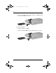
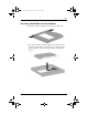
333644-001.book Page 6 Thursday, July 10, 2003 2:56 PM Drives 6. To remove the hard drive, lift the hard drive door 1, and pull the hard drive 2 out of the bay. To install a hard drive: 1. Lift the hard drive door 1. 2. Slide the hard drive 2 into the bay until the drive is seated.
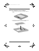
333644-001.book Page 7 Thursday, July 10, 2003 2:56 PM Drives 3. Do one of the following: ❏ If you have inserted a hard drive, reinsert the hard drive security screw 1 and hard drive retaining screw 2. ❏ If you removed but did not replace a hard drive, put the hard drive retaining screw and hard drive security screw in a safe place.
333644-001.book Page 8 Thursday, July 10, 2003 2:56 PM Drives MultiBay Drive This section explains how to use drives the MultiBay on the notebook. Identifying the MultiBay Activity Light The MultiBay activity light turns on when any MultiBay device is active, with the exception of the MultiBay battery pack. Using a MultiBay Hard Drive Adapter A hard drive must be inserted into an optional MultiBay hard drive adapter before it can be used in the MultiBay.
333644-001.book Page 9 Thursday, July 10, 2003 2:56 PM Drives Inserting a Hard Drive into the Adapter 1. Slide the 2 adapter selection switches to the outer edge. 2. Lower the hard drive into the adapter, then slide the drive connectors on the drive toward the drive connectors in the adapter until the connectors engage and the hard drive is seated.
333644-001.book Page 10 Thursday, July 10, 2003 2:56 PM Drives Removing a Hard Drive from the Adapter 1. Slide the adapter release latch to the outside as indicated below. 2. Gently disengage the drive connectors by sliding the drive away from the connectors, then remove the drive.
333644-001.book Page 11 Thursday, July 10, 2003 2:56 PM Drives Inserting a Hard Drive into the MultiBay inserting a hard drive into the MultiBay, insert the drive ✎ Before into a MultiBay hard drive adapter as described earlier in this chapter. Turn the notebook upside down. With the connector on the drive or drive assembly facing the MultiBay, slide the drive or drive assembly into the MultiBay until it is seated.
333644-001.book Page 12 Thursday, July 10, 2003 2:56 PM Drives Removing a Drive from the MultiBay Ä CAUTION: To prevent system lockup and loss of information, stop the drive before removing it. To stop the drive: ■ ■ Ä Windows 2000—Select the Unplug or Eject Hardware icon on the taskbar, then select the drive you want to remove. When it is safe to remove the drive, a message is displayed. Windows XP—Select the Safely Remove Hardware icon on the taskbar, then select the drive you want to remove.
333644-001.book Page 13 Thursday, July 10, 2003 2:56 PM Drives MultiBay Drive Media This section provides information on using optical discs (such as CD-ROMs and DVDs) and diskettes in the MultiBay. Inserting an Optical Disc 1. Turn on the notebook. 2. Press the release button 1 on the drive bezel to release the media tray. 3. Pull the tray out 2 until it is fully extended. Position a CD or one-sided DVD over the tray with the label side up. 4.
333644-001.book Page 14 Thursday, July 10, 2003 2:56 PM Drives Removing an Optical Disc (With Power) If power is available: 1. Turn on the notebook. 2. Press the release button 1 on the drive bezel to release the media tray, then pull the tray 2 out until it is fully extended. 3. Remove the disc 3 from the tray by gently pushing down on the spindle while lifting the outer edges of the disc. Handle the disc by the edges, not the flat surfaces.
333644-001.book Page 15 Thursday, July 10, 2003 2:56 PM Drives Removing an Optical Disc (No Power) If power is unavailable: 1. Insert the end of a paper clip 1 into the release access in the front bezel of the drive. 2. Press gently on the paper clip until the media tray is released, then pull out the tray 2 until it is fully extended. 3. Remove the disc 3 from the tray by gently pushing down on the spindle while lifting the outer edges of the disc. Handle the disc by the edges, not the flat surfaces.
333644-001.book Page 16 Thursday, July 10, 2003 2:56 PM Drives Inserting a Diskette To insert a diskette into a diskette drive, gently push the diskette, label side up, into the drive until it clicks into place. The media eject button pops out to show that the diskette has been inserted correctly. Removing a Diskette To remove a diskette from a diskette drive: 1. Press the eject button on the drive to eject the diskette. 2. Remove the diskette from the drive.
333644-001.book Page 17 Thursday, July 10, 2003 2:56 PM Drives Locating Optical Disc Software Software that plays CDs and DVDs is preloaded, but not preinstalled, on the notebook. You will need to install the software before you can use it. For more information, refer on the Documentation Library CD to the Software Guide, “Optical Drive Software” chapter.
333644-001.book Page 1 Thursday, July 10, 2003 2:56 PM 5 Audio and Video Using Audio Features The notebook includes the audio components described in the following table. Audio components Item Component Description 1 Audio line-out jack Connects optional, powered stereo speakers, headphones, headset, or television audio. 2 Microphone jack Connects an optional monaural microphone. 3 Mute button Mutes the system volume.
333644-001.book Page 2 Thursday, July 10, 2003 2:56 PM Audio and Video Audio components (Continued) Item Component Description 4 Volume buttons (2) Adjust the system volume. Press the volume up button to increase sound. Press the volume down button to decrease sound. 5 Speakers (2) Produce system sound. Using the Audio Line-Out Jack Å WARNING: To reduce the risk of personal injury, adjust the volume before putting on headphones or a headset.
333644-001.book Page 3 Thursday, July 10, 2003 2:56 PM Audio and Video Adjusting the Volume To adjust the volume, use any of the following controls: ■ ■ Notebook volume buttons ❏ To mute or restore volume, press the mute button. You can also mute or restore volume by pressing the volume – and volume + buttons simultaneously. ❏ To decrease the volume, press the volume down button. ❏ To increase the volume, press the volume up button.
333644-001.book Page 4 Thursday, July 10, 2003 2:56 PM Audio and Video Using Video Features The notebook features an S-Video out jack which connects the notebook to an optional S-Video device, such as a television, VCR, camcorder, overhead projector, or video capture card. The notebook can support one S-Video device connected to the S-Video out jack while simultaneously supporting an image on the notebook display and on any other supported external display.
333644-001.book Page 5 Thursday, July 10, 2003 2:56 PM Audio and Video Using the S-Video Jack To connect a video device to the S-Video jack: 1. Plug either end of the S-Video cable 1 into the S-Video jack on the notebook. 2. Connect the other end of the cable 2 to the video device as instructed in the documentation included with the device.
333644-001.book Page 1 Thursday, July 10, 2003 2:56 PM 6 Communication Devices Connecting a Modem Cable A modem cable, which has a 6-pin RJ-11 connector at each end, must be connected to an analog telephone line, in some countries, with the use of a country-specific modem adapter. Jacks for digital PBX systems may resemble analog telephone jacks, but are not compatible with the modem. Å WARNING: Connecting the notebook to a digital line can permanently damage the modem.
333644-001.book Page 2 Thursday, July 10, 2003 2:56 PM Communication Devices Using the RJ-11 Telephone Cable To connect an RJ-11 telephone cable: 1. Plug the modem cable 1 into the RJ-11 telephone jack on the notebook. Å WARNING: To avoid the risk of electrical shock, fire, or damage to the equipment, do not plug a telephone cable into the RJ-45 network jack. 2. Plug the modem cable 2 into the RJ-11 telephone jack.
333644-001.book Page 3 Thursday, July 10, 2003 2:56 PM Communication Devices Using a Country-Specific Adapter Cable Telephone jacks vary by country. To use the modem and the RJ-11 telephone cable outside the country in which you purchased the notebook, you must obtain a country-specific modem adapter. Refer on the Documentation Library CD to the Modem and Networking guide for more details about using your notebook internationally.
333644-001.book Page 4 Thursday, July 10, 2003 2:56 PM Communication Devices Connecting a Network Cable A network cable has an 8-pin RJ-45 connector at each end. If the network cable contains noise suppression circuitry, which prevents interference from TV and radio reception, orient the circuitry end of the cable toward the notebook. To connect the network cable: 1. Plug the network cable 1 into the RJ-45 network jack on the notebook. 2. Plug the other end of the cable 2 into a network jack. 3.
333644-001.book Page 5 Thursday, July 10, 2003 2:56 PM Communication Devices Linking to an Infrared Device The notebook is IrDA-compliant—4 megabits per second (Mbps) standard—and can communicate with another infrared-equipped device that is also IrDA-compliant. The infrared port supports both low-speed connections of up to 115 kilobits per second (Kbps) and high-speed connections of up to 4 Mbps.
333644-001.book Page 6 Thursday, July 10, 2003 2:56 PM Communication Devices Setting Up an Infrared Transmission For information about using infrared software, refer to your operating system Help file. To set up infrared devices for optimal transmission: ■ Prepare the infrared ports on both devices for transmission. ■ Position the devices so that their infrared ports face one another at a distance no greater than 1 meter (3.3 feet). ■ Position the ports so that they face one another directly.
333644-001.book Page 1 Thursday, July 10, 2003 2:56 PM 7 External Devices The jacks and connectors described in this guide support standard external devices. ■ For information about which jack or connector to use, refer to the documentation included with the device. ■ For information about installing or loading any software required by the device, such as drivers, refer to the documentation included with the device. To connect a standard external device to the notebook: 1. Turn off the notebook. 2.
333644-001.book Page 2 Thursday, July 10, 2003 2:56 PM External Devices Connecting a Monitor or Projector To connect an external monitor or projector to the notebook, insert the monitor cable into the external monitor connector on the back of the notebook. a properly connected external monitor or projector does not ✎ Ifdisplay hotkey to switch the image an image, try pressing the fn+f4 to the monitor.
333644-001.book Page 3 Thursday, July 10, 2003 2:56 PM External Devices Using a USB Device Universal serial bus (USB) is a hardware interface that can be used to connect external devices, such as a USB keyboard, mouse, drive, printer, scanner, or hub, to the notebook. The notebook has a standard USB connector 1 and a self-powered USB connector 2 that connects an optional external MultiBay. The USB connectors support USB 2.0 and USB 1.1 devices.
333644-001.book Page 4 Thursday, July 10, 2003 2:56 PM External Devices Enabling USB Legacy Support You must enable USB legacy support to: ■ Use a USB keyboard, mouse, or hub connected to a USB connector on the notebook during startup or in a non-Windows application or utility. ■ Boot from an optional external MultiBay. To enable USB legacy support: 1. Turn on or restart the notebook. 2. Press f10 while the F10 = ROM Based Setup message is displayed in the lower left corner of the screen.
3644-001.book Page 5 Thursday, July 10, 2003 2:56 PM External Devices Connecting an Optional External MultiBay An external MultiBay connects to the notebook by way of the self-powered USB connector and enables you to use MultiBay drives. For more information about the external MultiBay, refer to the documentation that is included with the device.
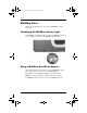
333644-001.book Page 6 Thursday, July 10, 2003 2:56 PM External Devices Connecting an Optional Cable Lock purpose of security solutions is to act as a deterrent. These ✎ The solutions do not prevent the product from being mishandled or stolen. To install a security cable: 1. Loop the security cable around a secured object. 2. Insert the cable lock key 1 into the cable lock. 3. Insert the cable lock 2 into the security cable slot 3. 4. Lock it with the cable lock key.
333644-001.book Page 1 Thursday, July 10, 2003 2:56 PM 8 Hardware Upgrades To order hardware or learn more about upgrades and accessories, visit the HP Web site at http://www.hp.com, or refer to Worldwide Telephone Numbers, included with the notebook, to contact an HP authorized dealer, reseller, or service provider. For information about obtaining and installing software updates and upgrades, refer on the Documentation Library CD to the Software Guide, “Software Updates and Restorations” chapter.
333644-001.book Page 2 Thursday, July 10, 2003 2:56 PM Hardware Upgrades Ä CAUTION: If you install software or enablers provided by a PC Card manufacturer, you may not be able to use other PC Cards. If you are instructed by the documentation included with your PC Card to install device drivers: ■ ■ Install only the device drivers for your operating system. Do not install other software, such as card services, socket services, or enablers, that may also be supplied by the PC Card manufacturer.
333644-001.book Page 3 Thursday, July 10, 2003 2:56 PM Hardware Upgrades Removing a PC Card Ä CAUTION: To prevent loss of work or an unresponsive system, stop the PC Card before removing it. 1. Stop the PC Card. ❏ In Windows 2000—Select the Unplug or Eject icon on the taskbar, then stop the card you plan to remove. When the card can be safely removed, a message is displayed. ❏ In Windows XP—Select the Safely Remove Hardware icon on the taskbar, then select the PC Card.
333644-001.book Page 4 Thursday, July 10, 2003 2:56 PM Hardware Upgrades Using SD Cards Secure Digital (SD) Cards are removable thumbnail-sized CompactFlash storage devices that provide a convenient method of storing data and sharing it with other devices such as PDAs, cameras, and other SD-equipped PCs. Inserting an SD Card Ä■ CAUTION: To prevent damage to the connectors: ■ Use minimal pressure when inserting an SD Card into an SD Card slot.
333644-001.book Page 5 Thursday, July 10, 2003 2:56 PM Hardware Upgrades Removing an SD Card Ä CAUTION: To prevent loss of work or system lockup, stop the SD Card before removing it. To remove an SD Card: 1. Close all files and applications using the SD Card. 2. Stop the SD Card. ❏ In Windows 2000, select the Unplug or Eject icon in the task bar, then stop the card you plan to remove. (When the card can be safely removed, a message is displayed.
333644-001.book Page 6 Thursday, July 10, 2003 2:56 PM Hardware Upgrades Adding and Upgrading Memory Modules Å WARNING: The memory compartments are the only user-accessible internal compartments on the notebook. All other areas that require a tool to open should be opened only by an authorized service provider. Å WARNING: Failure to unplug the power cord and remove all battery packs before installing a memory expansion module can damage the equipment and expose you to the risk of electrical shock.
333644-001.book Page 7 Thursday, July 10, 2003 2:56 PM Hardware Upgrades The memory capacity of the notebook can be upgraded by adding a memory module to the expansion slot or by upgrading the existing memory module in the primary memory slot. To add or upgrade a memory module: 1. Shut down the notebook. (If you are not sure whether the notebook is off or in Hibernation, turn the notebook on by pressing the power button. Then shut down the notebook through the operating system.) 2.
333644-001.book Page 8 Thursday, July 10, 2003 2:56 PM Hardware Upgrades 6. Open the notebook and slide the 4 keyboard latches down 1 to release the keyboard, then tilt the keyboard 2 and remove it from the notebook. 7. Press in on the latch 1 to release the memory slot cover 2, then tilt it up and remove it from the notebook.
333644-001.book Page 9 Thursday, July 10, 2003 2:56 PM Hardware Upgrades If replacing the existing memory in the primary memory slot, you must remove any memory in the memory expansion slot first. If you are adding memory to the memory expansion slot, proceed to step 9. 8. To remove a memory module from the memory expansion slot: a. Pull the retention clips 1 away from each side of the module. The module tilts upward when released. b.
333644-001.book Page 10 Thursday, July 10, 2003 2:56 PM Hardware Upgrades 9. To insert the new memory module into either memory slot: a. Align the keyed (notched) edge of the module 1 with the keyed area in the expansion slot. b. Press the module into the slot from a 45-degree angle until it is seated, then push the module 2 downward until the retention clips snap into place. 10. Replace the memory slot cover. 11. Replace the keyboard and snap the 4 keyboard latches back into place. 12.
333644-001.book Page 11 Thursday, July 10, 2003 2:56 PM Hardware Upgrades Effects of Increasing Memory When Random Access Memory (RAM) increases, the operating system increases the hard drive space reserved for the Hibernation file. If you experience problems with Hibernation after increasing RAM, verify that your hard drive has enough free space to accommodate a larger Hibernation file.
333644-001.book Page 1 Thursday, July 10, 2003 2:56 PM 9 Specifications The information in this chapter may be helpful if you plan to use or transport the notebook internationally or in extreme environments. compatible AC adapters and battery packs should be used ✎ Only with the notebook. For additional information, visit the HP Web site at http://www.hp.com or use the Worldwide Telephone Numbers booklet, included with your notebook, to contact an HP authorized dealer.
333644-001.book Page 2 Thursday, July 10, 2003 2:56 PM Specifications Notebook Dimensions Dimension U.S. Metric Height 1.28 in 3.26 cm Width 12.5 in 31.8 cm Depth 10.3 in 26.2 cm Operating Environment Factor U.S.
333644-001.book Page 3 Thursday, July 10, 2003 2:56 PM Specifications Rated Input Power Input power Rating Operating voltage 100–120/220–240 VAC RMS Operating current 1.7/0.85 A RMS Operating frequency range 47 to 63 Hz AC When powered by a DC source 18.5V MAX ✎ This product is designed for IT power systems in Norway with phase-to-phase voltage not exceeding 240 Vms. Modem Specifications This notebook has been tested and found to comply with the limits for a Class B digital device.
333644-001.book Page 1 Thursday, July 10, 2003 2:56 PM Index A AC adapter connecting 3–12 disconnecting 3–1 AC power 3–1 adapter, modem 6–3 Aircraft Power Adapter connecting 3–12 tasks supported by 3–6 airport security devices 4–2 altitude specifications 9–2 analog vs.
333644-001.book Page 2 Thursday, July 10, 2003 2:56 PM Index bay.
333644-001.
333644-001.book Page 4 Thursday, July 10, 2003 2:56 PM Index H hard drive bay 1–8 inserting into hard drive bay 4–5 inserting into MultiBay 4–11 locations supported 4–3 MultiBay vs.
333644-001.
333644-001.
333644-001.book Page 7 Thursday, July 10, 2003 2:56 PM Index S scroll lock light 1–6 SD (Secure Digital) Card 8–4, 8–5 Secure Digital (SD) slot 1–9 security cable slot 1–10 security features 7–6 shortcut keys defined 2–5 with external keyboards 2–8 Sleep.
333644-001.book Page 8 Thursday, July 10, 2003 2:56 PM Index operating environment specifications 9–2 protecting hardware connectors 8–4 U USB connectors 1–13, 7–3 devices 7–3, 7–4 hubs 7–3 legacy support 7–4 with power connector 1–13 utilities.