Installation and Getting Started Guide ProCurve Series 3500yl and 6200yl Switches PoE Power over Ethernet Devices www.procurve.
ProCurve Series 3500yl and 6200yl Switches Installation and Getting Started Guide
© Copyright 2005, 2008 Hewlett-Packard Development Company, L.P. The information contained herein is subject to change without notice. This document contains proprietary information, which is protected by copyright. No part of this document may be photocopied, reproduced, or translated into another language without prior written consent of Hewlett-Packard.
Contents 1 Introducing the Switch Front of the Switch . . . . . . . . . . . . . . . . . . . . . . . . . . . . . . . . . . . . . . . . . . . . . . 1-3 Network Ports . . . . . . . . . . . . . . . . . . . . . . . . . . . . . . . . . . . . . . . . . . . . . . 1-4 LEDs . . . . . . . . . . . . . . . . . . . . . . . . . . . . . . . . . . . . . . . . . . . . . . . . . . . . . . 1-5 LED Mode Select Button and Indicator LEDs . . . . . . . . . . . . . . . . . . . . 1-7 Reset Button . . . . . . . . . . . . . . . . . .
7. Connect the Switch to a Power Source . . . . . . . . . . . . . . . . . . . . . . 2-15 8. Connect the Network Cables . . . . . . . . . . . . . . . . . . . . . . . . . . . . . . . Using the RJ-45 Connectors . . . . . . . . . . . . . . . . . . . . . . . . . . . . . . Connecting Cables to mini-GBICs . . . . . . . . . . . . . . . . . . . . . . . . . Connecting a fiber cable . . . . . . . . . . . . . . . . . . . . . . . . . . . . . . . . . Connecting a copper cable . . . . . . . . . . . . . . . . . . . . . . .
5 Troubleshooting Basic Troubleshooting Tips . . . . . . . . . . . . . . . . . . . . . . . . . . . . . . . . . . . . . . 5-2 Diagnosing with the LEDs . . . . . . . . . . . . . . . . . . . . . . . . . . . . . . . . . . . . . . . . 5-4 Proactive Networking . . . . . . . . . . . . . . . . . . . . . . . . . . . . . . . . . . . . . . . . . . . 5-8 Hardware Diagnostic Tests . . . . . . . . . . . . . . . . . . . . . . . . . . . . . . . . . . . . . . . 5-9 Testing the Switch by Resetting It . . . . . . . . . . . .
Straight-Through Twisted-Pair Cable for 10 Mbps or 100 Mbps Network Connections . . . . . . . . . . . . . . . . . . . . B-6 Cable Diagram . . . . . . . . . . . . . . . . . . . . . . . . . . . . . . . . . . . . . . . . . B-6 Pin Assignments . . . . . . . . . . . . . . . . . . . . . . . . . . . . . . . . . . . . . . . . B-6 Crossover Twisted-Pair Cable for 10 Mbps or 100 Mbps Network Connection . . . . . . . . . . . . . . . . . . . . . B-7 Cable Diagram . . . . . . . . . . . . . . . . . . . . . . . . . . . .
1 The ProCurve Switches 3500yl and 6200yl are multiport switches that can be used to build high-performance switched networks. These switches are storeand-forward devices offering low latency for high-speed networking. The 3500yl switches also support Redundant Power Supply and Power over Ethernet technologies. The 6200yl switch supports Redundant Power Supply only.
Introducing the Switch Introducing the Switch One slot is provided in the back of the device to support a four port (two fixed CX4 ports and two X2 transceiver ports) 10 Gigabit per second Ethernet (10GbE) module to provide box connectivity to other switch boxes, to a 10 Gigabit per second concentrator or to any Ethernet compatible uplink. The Series 3500yl Switches are also designed to support Power over Ethernet (PoE) technology. The switches support 802.
Introducing the Switch Front of the Switch PoE, Temp, Fan, and Test Status LEDs Power, Fault, and Locator LEDs Auxiliary port and LED* Introducing the Switch Front of the Switch Switch port LEDs Module, EPS, and RPS, Status LEDs 3500yl-24G J8692A Status Power PoE FDx Fault Fan LED Mdl EPS RPS Status of the Back *Spd mode: PoE-Integrated 10/100/1000Base-T Ports (1 - 24T) Ports are IEEE Auto MDI/MDI-X off = 10 Mbps flash = 100 Mbps Dual-Personality Ports: 10/100/1000-T (T) or Mini-GBIC
Introducing the Switch Introducing the Switch Front of the Switch Power, Fault, and locator LEDs Temp, Fan, and Test Status LEDs ProCurve Switch 6200yl-24G Auxiliary port and LED Switch port LEDs Module and RPS Status LEDs Power Fault Locator Console port Reset and Clear buttons Port LED Mode select button and indicator LEDs Mini-GBIC ports Figure 1-3. Front of the ProCurve Switch 6200yl-24G. Network Ports ■ 24 or 48 auto-sensing 10/100/1000Base-T ports.
Introducing the Switch Front of the Switch LEDs Introducing the Switch Table 1-1. Switch LEDs Switch LEDs State Meaning Power (green) On Off The switch is receiving power. The switch is NOT receiving power. Fault (orange) Off The normal state; indicates there are no fault conditions on the switch. blink orange* A fault has occurred on the switch, one of the switch ports, module in the rear of the switch, or the fan. The Status LED for the component with the fault will blink simultaneously.
Introducing the Switch Introducing the Switch Front of the Switch Switch LEDs State Meaning Spd Indicates the port LEDs are displaying the connection speed at which each port is operating: • if the port LED is off, the port is operating at 10 Mbps. • if the port LED is blinking**, the port is operating at 100 Mbps. • if the port LED is on continuously, the port is operating at 1000 Mbps.
Introducing the Switch Front of the Switch LED Mode Select Button and Indicator LEDs Port LEDs Link and Mode Expansion Module LED ProCurve Switch Mdl 3500yl-24G J8692A PoE Fault Fan RPS Status of the Back *Spd mode: PoE-Integrated 10/100/1000Base-T Ports (1 off = 10 Mbps flash = 100 Mbps Link 1 Mode 3 5 7 9 11 Link 2 Mode 4 6 8 10 12 on = 1000 Mbps Act Status Power EPS PoE LED FDx Tmp Mode Spd * PoE Test Locator Usr Reset Auxiliary Port Console Clear LED Mode selec
Introducing the Switch Introducing the Switch Front of the Switch ■ Each port has a Link LED. If it is lit, the port has a link. If the Link LED is blinking, the port has failed its self test. The Fault and Self Test LEDs will be blinking simultaneously. ■ If the Activity (Act) indicator LED is lit, each port LED displays activity information for the associated port—it flickers as network traffic is received and transmitted through the port.
Introducing the Switch Front of the Switch Clear Button ■ Deleting Passwords - When pressed by itself for at least one second, the button deletes any switch console access passwords that you may have configured. Use this feature if you have misplaced the password and need console access.
Introducing the Switch Front of the Switch Introducing the Switch Table 1-2. Name Color Mode Expansion Module LEDs Description Expansion Module LEDs per module Module (Mdl) Power Module (Mdl) Fault Green Orange On Expansion module is plugged into expansion slot and operating correctly Off Expansion module's power has been turned OFF, and the card can be removed from the box if necessary.
Introducing the Switch Back of the Switch Introducing the Switch Back of the Switch EPS Input Port Serial No. SG12345678 0001e7 System MAC Address 123456 CAUTION: MULTIPLE POWER SOURCES Disconnect all AC power cords, and EPS and RPS cables to completely remove power from the unit. 12V System Power (RPS) Input 50V PoE (EPS) Input PoE Connect ProCurve 620 EPS only RPS Input Port yl module slot Line: 50/60 Hz. 100-127 V~ 10 A 200-240 V~ 5 A AC power connector Figure 1-7.
Introducing the Switch Back of the Switch Introducing the Switch yl Module Slot These switches support one yl module. The yl module provides 4 ports: ■ two 10-GbE CX4 fixed copper ports ■ two 10-GbE flexible media slots that support a number of different transceivers. See the ProCurve Switch yl Module Installation Guide for more information on supported transceivers. RPS and EPS Input Port The Series 3500yl and 6200yl Switches support connectivity to a redundant power supply.
Introducing the Switch Switch Features The features of the Series 3500yl and 6200yl Switches include: ■ 24 or 48 auto-sensing 10/100/1000Base-T RJ-45 ports with HP Auto-MDIX. ■ Four dual-personality ports—either the auto sensing 10/100/1000Base-T RJ-45 or the mini-GBIC can be used for each port. ■ The 6200yl provides 24 mini-GBIC ports.
Introducing the Switch Introducing the Switch Switch Features 1-14 • web browser interface—an easy to use built-in graphical interface that can be accessed from common web browsers. • ProCurve Manager—an SNMP-based, graphical network management tool that you can use to manage your entire network. This product is included with your new switch. ■ Support for the Spanning Tree Protocol to eliminate network loops ■ Support for up to 2048 IEEE 802.
2 Installing the Switch Caution If the switch is to be shipped in a rack, be sure to use only an HP 10K rack. Mount the switch using rail kit, ProCurve 1U RK MT SWITCH 10K ALL, part number 356578-B21 and shelf kit AB469A, HP rx 16/26 Factory Rackmount Shelf Kit. Both kits must be used. Otherwise you will void the warranty.
Installing the Switch Included Parts ■ Accessory kit (5069-5705) for both the Series 3500yl and 6200yl Switches two mounting brackets eight 8-mm M4 screws to attach the mounting brackets to the switch four 5/8-inch number 12-24 screws to attach the switch to a rack four rubber feet Installing the Switch ■ Power cord, one of the following: Australia/New Zealand China Continental Europe Denmark Japan Switzerland United Kingdom/Hong Kong/Singapore United States/Canada/Mexico South Africa and India Argentin
Installing the Switch Installation Procedures Installation Procedures Summary Prepare the installation site (page 2-5). Ensure the physical environment is properly prepared, including having the correct network cabling ready to connect to the switch and having an appropriate location for the switch. See page 2-4 for some installation precautions. 2. Install or remove a yl module (optional—page 2-7). 3. Install or remove a transceiver (optional—(page 2-8).
Installing the Switch Installation Procedures Installation Precautions: Follow these precautions when installing the Series 3500yl or 6200yl Switches. Installing the Switch WARNING Cautions ■ The rack or cabinet should be adequately secured to prevent it from becoming unstable and/or falling over. ■ Devices installed in a rack or cabinet should be mounted as low as possible, with the heaviest devices at the bottom and progressively lighter devices installed above.
Installing the Switch Installation Procedures 1. Prepare the Installation Site Cabling Infrastructure - Ensure the cabling infrastructure meets the necessary network specifications. The copper ports accept CX4 cable with Infiniband-style connectors or fiber cable using a CX4 optical media converter (OMC). The fiber ports accept single-mode fiber optic cable with SC connectors.
Installing the Switch Installation Procedures Port Type Cable Type Length Limits Installing the Switch Fiber Optic Cables Gigabit-SX (on Gigabit-SX-LC mini-GBIC) Multimode fiber-optic cables designed for Gigabit Ethernet: 62.5/125 μm or 50/125 μm (core/cladding) diameter, 850 nm, low metal content, graded-index cables, fitted with LC connectors. The cables must comply with the ITU-T G.651 and ISO/IEC 793-2 Type A1b or A1a standards. • 62.
Installing the Switch Installation Procedures ■ Installation Location - Before installing the switch, plan its location and orientation relative to other devices and equipment: • In the front of the switch, leave at least 7.6 cm (3 inches) of space for the twisted-pair and fiber-optic cabling. • In the back of the switch, leave at least 3.8 cm (1 1/2 inches) of space for the power cord. • On the sides of the switch, leave at least 7.
Installing the Switch Installation Procedures 3. (Optional) Install or Remove a Transceiver Note Hot swapping transceivers is supported. You can install or remove a transceiver with the switch powered on, a reset will not occur. Installing the Switch a. Slide the transceiver in until it stops.1 Figure 2-2. Installing a fiber optic transceiver.
Installing the Switch Installation Procedures 4. (Optional) Install or Remove mini-GBICs You can install or remove a mini-GBIC from a mini-GBIC slot without having to power off the switch. Use only ProCurve mini-GBICs. Notes ■ The mini-GBIC slots are shared with the four 10/100/1000Base-T RJ-45 ports. If a mini-GBIC is installed in a slot, the associated RJ-45 port is disabled and cannot be used. ■ The mini-GBIC ports operate only at full duplex. Half duplex operation is not supported.
Installing the Switch Installation Procedures Removing the mini-GBICs: Note You should disconnect the network cable from the mini-GBIC before removing it from the switch. Depending on when you purchased your ProCurve mini-GBIC, it may have either of three different release mechanisms: a plastic tab on the bottom of the mini-GBIC, a plastic collar around the mini-GBIC, or a wire bail.
Installing the Switch Installation Procedures 5. Verify the Switch Passes Self Test Before mounting the switch in its network location, you should first verify it is working properly by plugging it into a power source and verifying it passes self test. 1. Connect the power cord supplied with the switch to the power connector on the back of the switch, and then into a properly grounded electrical outlet. Installing the Switch Figure 2-5. Connecting the power cord.
Installing the Switch Installation Procedures 2. Check the LEDs on the switch as described below.
Installing the Switch Installation Procedures LED Behavior: During the self test: • Initially, all the status, LED Mode and port LEDs are on for most of the duration of the test. • Most of the LEDs go off and then may come on again during phases of the self test. For the duration of the self test, the Test LED stays on. When the self test completes successfully: The Power and Fan Status LEDs remain on. • The Fault and Test LEDs go off.
Installing the Switch Installation Procedures Equipment Cabinet Note The 12-24 screws supplied with the switch are the correct threading for standard EIA/TIA open 19-inch racks. If you are installing the switch in an equipment cabinet such as a server cabinet, use the clips and screws that came with the cabinet in place of the 12-24 screws that are supplied with the switch. Complete step 1, and plan which four holes you will be using in the cabinet and install all four clips. Then proceed to step 2.
Installing the Switch Installation Procedures 2. Hold the switch with attached brackets up to the rack and move it vertically until rack holes line up with the bracket holes, then insert and tighten the four number 12-24 screws holding the brackets to the rack. Installing the Switch Figure 2-8. Mounting the switch in a rack. Horizontal Surface Mounting Place the switch on a table or other horizontal surface.
Installing the Switch Installation Procedures 8. Connect the Network Cables Connect the network cables, described under “Cabling Infrastructure” (page 2-5), from the network devices or your patch panels to the fixed RJ-45 ports on the switch or to any mini-GBICs you have installed in the switch. Using the RJ-45 Connectors Installing the Switch To connect: Push the RJ-45 plug into the RJ-45 jack until the tab on the plug clicks into place.
Installing the Switch Installation Procedures Connecting a fiber cable To connect: 1. Remove the dust covers from the cable connectors and the port. 2. Aligning the notches on the cable connectors with the slots of the port, press the cable connector into the port until it snaps into place. 1 2 To disconnect: Pull the cable connector straight out. Connecting a copper cable To connect: 1. Push the copper cable connector into the copper port. Ensure the locking device locks the cable connector into place.
Installing the Switch Installation Procedures 9. (Optional) Connect a 620 Redundant Power Supply to the switch Installing the Switch The ProCurve 620 Redundant and External Power Supply, (J8696A), hereafter referred to as the 620 RPS/EPS, is an accessory product for the Series 3500yl and 6200yl switches and specific other ProCurve switches.
Installing the Switch Installation Procedures Operating Characteristics of the 620 RPS/EPS (J8696A) The 620 RPS/EPS has two RPS ports, each of which can provide redundant +12V power to a connected switch. If a switch with no AC power is connected to an operating 620 RPS/EPS, it will not receive power. The switch must first be powered on, then connected to the 620 RPS/EPS. For redundant AC power, connect the 620 RPS/EPS to the switch using one of the supplied RPS cables.
Installing the Switch Installing the Switch Installation Procedures LED State Meaning Power (green) On The unit is powered on. Off The unit is NOT powered on. Fault (orange) Off The normal state; indicates that there are no fault conditions on the unit. Blink orange1,3 A fault has occurred on the unit, one of the ports, or the fan. The Status LED for the component with the fault will blink simultaneously.
Installing the Switch Installation Procedures 620 RPS/EPS Connectivity This section shows some recommended connection topologies using the 620 RPS/EPS. The 620 RPS/EPS can provide backup power support for up to two ProCurve switches. In the illustration below, two ProCurve Switch 3500yl24G-PWR units are connected to the RPS ports on a 620 RPS/EPS. Installing the Switch Figure 2-13. Connecting RPS to 2, 24 port switches.
Installing the Switch Installation Procedures 10.
Installing the Switch Installation Procedures Direct Console Access To connect a console to the switch, follow these steps: ProC ur ve Switc h 3500y l J8692A 1. 3. Turn on the terminal or PC’s power and, if using a PC, start the PC terminal program.
Installing the Switch Sample Network Topologies Sample Network Topologies This section shows a few sample network topologies in which the switch is implemented. For more topology information, see the ProCurve network products Web site, www.procurve.com.
Installing the Switch Sample Network Topologies ProCurve 620 RPS/EPS Server ProCurve Switch 3500yl-24G Installing the Switch IP Telephones Twisted-pair straight-through or crossover cables Wireless Access Point PCs and peripherals Figure 2-17. As a Desktop Switch Implementing PoE. This illustration is the same as figure 2-16, except now the switch is configured to supply PoE power to end devices such as IP telephones and wireless access points (WAPs).
Installing the Switch Sample Network Topologies Server with Gigabit Ethernet NIC ProCurve Switch 3500yl-24G J8692A Fault Installing the Switch RPS S tatus of the Back * Spd mode: PoE-Int egrated 10/1 00/1 000Base-T P orts (1 - 24T) — Ports are IEEE A uto MDI/MDI- X off = 10 Mbps flash = 100 Mbps 1 Mode 3 5 7 9 11 Link 13 Mode 15 17 19 21T 23 T Link 21M Mode 23 M Link 2 Mode 4 6 8 10 12 Link 14 Mode 16 18 20 22 T 24T Link 22 M Mode 24M on = 1 000 Mbps P oE F
Installing the Switch Sample Network Topologies Because the Switch has the “IEEE Auto MDI/MDI-X” features, the connections between the switch and the hubs, and between the switch and end nodes or servers can be through category 5 straight-through or crossover twisted-pair cable. Category 3 or 4 cable can also be used if the connection is 10 Mbps only. In all cases, the device ports must be configured to auto negotiate the link characteristics for this feature to work.
Installing the Switch Sample Network Topologies To IT or Data Center PCs, local servers, and peripherals Servers with Gigabit Ethernet NIC ProCurve Switch 5406zl Installing the Switch ProCurve Switch 3500yl-24G Gigabit link (use fiber if over 100 meters) ProCurve Switch 3500yl-48G Servers with Gigabit Ethernet NIC Servers with Gigabit Ethernet NIC Fast Ethernet Switch LEGEND: Fast Ethernet cable Fast Ethernet Switch PCs, local servers, and peripherals Servers with Gigabit Ethernet NIC Gigabit
Installing the Switch Sample Network Topologies Note In the Backbone Switch illustration, the 1000 Mbps fiber-optic connection between the Switch 3500yl-24G and the Switch 5304xl is by way of a GigabitSX mini-GBIC installed in the Switch 3500yl-24G and connected to a GigabitSX Module in the Switch 5304xl. Stacking the Switch The Series 3500yl Switches can be connected together, through standard network connections, and managed through a single IP address.
Installing the Switch Sample Network Topologies Stack of two 3500yl-24G switches using CX4 cables trunked. CAUTION: MUL TIPLE PO WER SOUR CES Serial No. SG12345678 System MAC Address ProCur ve Switc h yl X2/CX4 10-GbE Module 10-GbE X2 Port 00 -01-E7 -12-34 -56 1 2 1 Link 4 12V Sys tem Power (RPS) Input 10-GbE CX4 Ports 50V P oE (EPS) Input P oE 3 3 2 Disconnect all AC power cords, and EPS and RPS cables to completely remove power from the unit.
Installing the Switch Sample Network Topologies Stack of three 3500yl-24G switches using CX4 and fiber cables trunked. CAUTION: MUL TIPLE PO WER SOUR CES Serial No. SG12345678 System MAC Address ProCur ve Switc h yl X2/CX4 10-GbE Module 10-GbE X2 Port 00 -01-E7 -12-34 -56 1 2 1 Link 10-GbE X2 Port 12V Sys tem Power (RPS) Input 10-GbE CX4 Ports 50V P oE (EPS) Input P oE 3 3 2 Disconnect all AC power cords, and EPS and RPS cables to completely remove power from the unit.
Installing the Switch Sample Network Topologies When any two 10-GbE ports are in a linked state, each port automatically operates on its own channel, which guarantees 10 Gbps of bandwidth for each port. However, when more than two ports are in a linked state, ports A1 and A4 are statically mapped to share one 14.4 Gbps channel, while ports A2 and A3 are statically mapped to share the other 14.4 Gbps channel.
3 Getting Started With Switch Configuration This chapter is a guide for using the console Switch Setup screen to quickly assign an IP (Internet Protocol) address and subnet mask to the switch, set a Manager password, and, optionally, configure other basic features.
Getting Started With Switch Configuration Using the Console Setup Screen Note By default, the switch is configured to acquire an IP address configuration from a DHCP or Bootp server. To use DHCP/Bootp instead of the manual method described in this chapter, see “DHCP/Bootp Operation” in the Management and Configuration Guide, which is on the ProCurve Web site, www.procurve.com. (See page 5-1 for details.
Getting Started With Switch Configuration Using the Console Setup Screen 4. [Tab] to the IP Config (DHCP/Bootp) field and use the Space bar to select the Manual option. 5. [Tab] to the IP Address field and enter the IP address that is compatible with your network. 6. [Tab] to the Subnet Mask field and enter the subnet mask used for your network. 7. Press [Enter], then [S] (for Save). Here is some information on the fields in the Setup screen.
Getting Started With Switch Configuration Where to Go From Here Where to Go From Here The above procedure configures your switch with a Manager password, IP address, and subnet mask. As a result, with the proper network connections, you can now manage the switch from a PC equipped with Telnet, a web browser interface, or from an SNMP-based network management station using a tool such as ProCurve Manager. Some basic information on managing your switch is included in the next section.
Getting Started With Switch Configuration Using the IP Address for Remote Switch Management Using the IP Address for Remote Switch Management With your yl switch, you can use the switch’s IP address to manage the switch from any PC that is on the same subnet as the switch. You can use either a Telnet session or a standard web browser to manage the switch. Starting a Telnet Session To access the switch through a Telnet session, follow these steps: 1.
Getting Started With Switch Configuration Using the IP Address for Remote Switch Management The operating systems, web browsers, and Java support required to manage the switch through the browser interface are listed in the following table: Operating System Internet Explorer Java Version Windows 2000 SP4 5.5 SP2, 6.0 SP1 1.3.1_12 and 1.4.2_05 Windows XP SP1a 6.0 SP1 1.3.1_12 and 1.4.2_05 Windows Server 2003 6.0 SP1 1.3.1_12 and 1.4.
4 Replacing Components This chapter shows you how to remove and install the following components: Hot Swapping Caution ■ Fan tray (see page 4-1) ■ Battery (see page 4-3) These components can not be hot swapped. The switch must be powered off to replace both of these components. The ProCurve 3500yl and 6200yl Switches and its components are sensitive to static discharge. Use an antistatic wrist strap and observe all static precautions when replacing components.
Replacing Components Replacing the fan tray 3. Remove the retaining screw securing the fan tray, disconnect the fan tray cable connector, and lift the fan tray assembly out. Retaining Screw Cable Connector Figure 4-1. Fan tray retaining screw and cable. 4. Install the new fan tray assembly, reconnect the fan tray cable connector, reinstall and tighten the retaining screw. 5. Reinstall the top of the switch. Align the top cover pin with the hole.
Replacing Components Replacing the Battery Replacing the Battery The battery is used to keep time for the internal switch clock. There is not LED indicator for when the battery no longer has sufficient power. The only indication will be the internal clock will not keep the correct time. The battery is not hot swappable. Replacing the battery must be done during scheduled downtime. WARNING ■ The battery requires special handling at end-of-life.
Replacing Components Replacing the Battery 4. Insert a new battery with the lettering and the plus “+” sign facing up. Be sure to replace with the same type of battery. 5. Reinstall the top of the switch. Ensure you correctly align the top cover pin. Top Cover Pin Alignment Hole Figure 4-4. Alignment of the top cover pin with the alignment hole. AT T E N T I O N 6. Reinstall and tighten all the screws securing the top. 7. Reconnect the power cable to the switch.
5 Troubleshooting Troubleshooting This chapter describes how to troubleshoot your switch. This document describes troubleshooting mostly from a hardware perspective. You can perform more in-depth troubleshooting on the switch using the software tools available with the switch, including the full-featured console interface, the built-in web browser interface, and ProCurve Manager, the SNMP-based network management tool.
Troubleshooting Basic Troubleshooting Tips Troubleshooting Basic Troubleshooting Tips Most problems are caused by the following situations. Check for these items first when starting your troubleshooting: ■ Connecting to devices that have a fixed full-duplex configuration. The RJ-45 ports are configured as “Auto”.
Troubleshooting Basic Troubleshooting Tips For your switch, if you wish to build redundant paths between important nodes in your network to provide some fault tolerance, you should enable Spanning Tree Protocol support on the switch. This ensures only one of the redundant paths is active at any time, thus avoiding data path loops. Spanning Tree can be enabled through the switch console, the web browser interface, or ProCurve Manager.
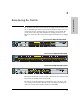
Troubleshooting Diagnosing with the LEDs Troubleshooting Diagnosing with the LEDs Table 4-1 shows LED patterns on the switch and the switch modules that indicate problem conditions. 1. Check in the table for the LED pattern you see on your switch. 2. Refer to the corresponding diagnostic tip on the next few pages. Table 5-1.
Troubleshooting Diagnosing with the LEDs Diagnostic Tips: Problem Solution ➊ The switch is not plugged into an active AC power source, or the switch’s power supply may have failed. The switch will not power up if the top is off. 1. Verify the power cord is plugged into an active power source and to the switch. Make sure these connections are snug. 2. Try power cycling the switch by unplugging and plugging the power cord back in. 3.
Troubleshooting Troubleshooting Diagnosing with the LEDs Tip Problem Solution ➏ The network connection is not working properly. Try the following procedures: • For the indicated port, verify both ends of the cabling, at the switch and the connected device, are connected properly. • Verify the connected device and switch are both powered on and operating correctly.
Troubleshooting Diagnosing with the LEDs Problem Solution ➐ The port may be improperly configured, or the port may be in a “blocking” state by the normal operation of the Spanning Tree, LACP, or IGMP features. Use the switch console to see if the port is part of a dynamic trunk (through the LACP feature) or to see if Spanning Tree is enabled on the switch, and to see if the port may have been put into a “blocking” state by those features.
Troubleshooting Proactive Networking Troubleshooting Proactive Networking The ProCurve Series 3500yl and 6200yl Switches have built-in management capabilities that proactively help you manage your network including: ■ finding and helping you fix the most common network error conditions (for example, faulty network cabling, and non-standard network topologies) ■ informing you of the problem with clear, easy-to-understand messages ■ recommending network configuration changes to enhance the performance
Troubleshooting Hardware Diagnostic Tests Testing the Switch by Resetting It If you believe the switch is not operating correctly, you can reset the switch to test its circuitry and operating code.
Troubleshooting Hardware Diagnostic Tests Testing Twisted-Pair Cabling Troubleshooting Network cables that fail to provide a link or provide an unreliable link between the switch and the connected network device may not be compatible with the IEEE 802.3 Type 10Base-T, 100Base-TX, or 1000Base-T standards. The twistedpair cables attached to the Switch must be compatible with the appropriate standards. To verify your cable is compatible with these standards, use a qualified cable test device.
Troubleshooting Restoring the Factory Default Configuration As part of your troubleshooting process on the switch, it may become necessary to return the switch configuration to the factory default settings. This process momentarily interrupts the switch operation, clears any passwords, clears the console event log, resets the network counters to zero, performs a complete self test, and reboots the switch into its factory default configuration including deleting the IP address, if one is configured.
Troubleshooting Downloading New Switch Software Troubleshooting Downloading New Switch Software When product enhancements occur for the switch, new software can be downloaded to the switch through several methods, for product enhancements and new features. For more information, see the Management and Configuration Guide, which is on the ProCurve Web site at www.procurve.com. See page 5-1 for details. The new switch software would be available on the ProCurve Web site, www.procurve.com.
A Specifications Physical 3500yl-48G (J8693A) Width: 44.3 cm (17.42 in) 44.3 cm (17.42 in) Depth: 39.2 cm (15.43 in) 43.0 cm (16.9 in) Height: 4.4 cm (1.7 in) 4.4 cm (1.7 in) Weight: 6.4 kg (14.10 lbs) 7.3 kg (16.1 lbs) Specifications 3500yl-24G (J8692A) and 6200yl-24G(J8992A) Electrical The switch automatically adjusts to any voltage between 100-127 and 200-240 volts and either 50 or 60 Hz.
Specifications Acoustic ProCurve Switch 3500yl-24G-PWR (J8692A) and ProCurve Switch 6200yl-24G-mGBIC (J8992A) Geraeuschemission LpA=49.3 dB am fiktiven Arbeitsplatz nach DIN 45635 T.19 Noise Emission LpA=49.3 dB at virtual workspace according to DIN 45635 T.19 ProCurve Switch 3500yl-48G-PWR (J8692A) Specifications Geraeuschemission LpA=52 dB am fiktiven Arbeitsplatz nach DIN 45635 T.19 Noise Emission LpA=52 dB at virtual workspace according to DIN 45635 T.
Running H/F 1 Lasers The following products are Class 1 Laser Products. Laser Klasse 1: ■ The 10-GbE X2-SC SR transceiver ■ The 10-GbE X2-SC LR transceiver ■ The 10-GbE X2-SC ER transceiver The following products are Class 1m Laser Products. Laser Klasse 1m: ■ The 10-GbE X2 SR-SC transceiver The transceivers comply with IEC 60825.
B Switch Ports and Network Cables This appendix includes switch connector information and network cable information for cables that should be used with the Switch 3500, including minimum pin-out information and specifications for twisted-pair cables. Note Incorrectly wired cabling is the most common cause of problems for LAN communications. ProCurve recommends that you work with a qualified LAN cable installer for assistance with your cabling requirements.
Switch Ports and Network Cables Because of the increased speed provided by 1000Base-T (Gigabit-T), network cable quality is more important than for either 10Base-T or 100Base-TX. Cabling plants being used to carry 1000Base-T networking must comply with the IEEE 802.3ab standards. In particular, the cabling must pass tests for Attenuation, Near-End Crosstalk (NEXT), and Far-End Crosstalk (FEXT).
Switch Ports and Network Cables Mode Conditioning Patch Cord for Gigabit-LX Mode Conditioning Patch Cord for Gigabit-LX The following information applies to installations in which multimode fiberoptic cables are connected to a Gigabit-LX port. Note Mode Conditioning Patch Cord cables only apply to one Gigabit operation. Mode Conditioning Patch Cord cables are not supported for 10 Gigabit operation.
Switch Ports and Network Cables Mode Conditioning Patch Cord for Gigabit-LX Installing the Patch Cord As shown in the illustration below, connect the patch cord to the Gigabit-LX mini-GBIC with the section of single-mode fiber plugged in to the Tx (transmit) port. Then, connect the other end of the patch cord to your network cabling patch panel, or directly to the network multimode fiber.
Switch Ports and Network Cables Twisted-Pair Cable/Connector Pin-Outs Twisted-Pair Cable/Connector Pin-Outs Auto-MDIX Feature: The 10/100/1000-T ports support the IEEE 802.3ab standard, which includes the “Auto MDI/MDI-X” feature. In the default configuration, “Auto”, the ports on the Switch 3500 all automatically detect the type of port on the connected device and operate as either an MDI or MDIX port, whichever is appropriate.
Switch Ports and Network Cables Twisted-Pair Cable/Connector Pin-Outs Straight-Through Twisted-Pair Cable for 10 Mbps or 100 Mbps Network Connections Because of the HP Auto-MDIX operation of the 10/100 ports on the switch, for all network connections, to PCs, servers or other end nodes, or to hubs or other switches, you can use straight-through cables.
Switch Ports and Network Cables Twisted-Pair Cable/Connector Pin-Outs Crossover Twisted-Pair Cable for 10 Mbps or 100 Mbps Network Connection The HP Auto-MDIX operation of the 10/100 ports on the switch also allows you to use crossover cables for all network connections, to PCs, servers or other end nodes, or to hubs or other switches.
Switch Ports and Network Cables Twisted-Pair Cable/Connector Pin-Outs Straight-Through Twisted-Pair Cable for 1000 Mbps Network Connections 1000Base-T connections require that all four pairs or wires be connected. Switch Ports and Network Cables Cable Diagram Note Pins 1 and 2 on connector “A” must be wired as a twisted pair to pins 1 and 2 on connector “B”. Pins 3 and 6 on connector “A” must be wired as a twisted pair to pins 3 and 6 on connector “B”.
C Safety and EMC Regulatory Statements Safety Information ! Documentation reference symbol. If the product is marked with this symbol, refer to the product documentation to get more information about the product. WARNING A WARNING in the manual denotes a hazard that can cause injury or death. Caution A Caution in the manual denotes a hazard that can damage equipment. Do not proceed beyond a WARNING or Caution notice until you have understood the hazardous conditions and have taken appropriate steps.
Safety and EMC Regulatory Statements Informations concernant la sécurité Informations concernant la sécurité ! Symbole de référence à la documentation. Si le produit est marqué de ce symbole, reportez-vous à la documentation du produit afin d'obtenir des informations plus détaillées. WARNING Dans la documentation, un WARNING indique un danger susceptible d'entraîner des dommages corporels ou la mort.
Safety and EMC Regulatory Statements Hinweise zur Sicherheit Hinweise zur Sicherheit ! Symbol für Dokumentationsverweis. Wenn das Produkt mit diesem Symbol markiert ist, schlagen Sie bitte in der Produktdokumentation nach, um mehr Informationen über das Produkt zu erhalten. WARNING Eine WARNING in der Dokumentation symbolisiert eine Gefahr, die Verletzungen oder sogar Todesfälle verursachen kann. Caution Caution in der Dokumentation symbolisiert eine Gefahr, die dis Gerät beschädigen kann.
Safety and EMC Regulatory Statements Considerazioni sulla sicurezza Considerazioni sulla sicurezza ! Simbolo di riferimento alla documentazione. Se il prodotto è contrassegnato da questo simbolo, fare riferimento alla documentazione sul prodotto per ulteriori informazioni su di esso. WARNING La dicitura WARNINGdenota un pericolo che può causare lesioni o morte. Caution La dicituraCaution denota un pericolo che può danneggiare le attrezzature.
Safety and EMC Regulatory Statements Consideraciones sobre seguridad Consideraciones sobre seguridad ! Símbolo de referencia a la documentación. Si el producto va marcado con este símbolo, consultar la documentación del producto a fin de obtener mayor información sobre el producto. WARNING Una WARNING en la documentación señala un riesgo que podría resultar en lesiones o la muerte. Caution Una Caution en la documentación señala un riesgo que podría resultar en averías al equipo.
Safety and EMC Regulatory Statements Safety Information (Japan) Safety and EMC Regulatory Statements Safety Information (Japan) Japan Power Cord Warning C-6
Safety and EMC Regulatory Statements Safety Information (China) Safety Information (China) Safety and EMC Regulatory Statements C-7
Safety and EMC Regulatory Statements EMC Regulatory Statements EMC Regulatory Statements U.S.A. FCC Class A This equipment has been tested and found to comply with the limits for a Class A digital device, pursuant to Part 15 of the FCC Rules. These limits are designed to provide reasonable protection against interference when the equipment is operated in a commercial environment.
Safety and EMC Regulatory Statements EMC Regulatory Statements Korea Taiwan Safety and EMC Regulatory Statements C-9
Safety and EMC Regulatory Statements EMC Regulatory Statements Safety and EMC Regulatory Statements European Community C-10
D Recycle Statements Recycle Statements Waste Electrical and Electronic Equipment (WEEE) Statements Disposal of Waste Equipment by Users in Private Household in the European Union This symbol on the product or on its packaging indicates that this product must not be disposed of with your other household waste. Instead, it is your responsibility to dispose of your waste equipment by handing it over to a designated collection point for the recycling of waste electrical and electronic equipment.
Recycle Statements Waste Electrical and Electronic Equipment (WEEE) Statements Recycle Statements Laitteiden hävittäminen kotitalouksissa Euroopan unionin alueella Jos tuotteessa tai sen pakkauksessa on tämä merkki, tuotetta ei saa hävittää kotitalousjätteiden mukana. Tällöin hävitettävä laite on toimitettava sähkölaitteiden ja elektronisten laitteiden kierrätyspisteeseen.
Recycle Statements Waste Electrical and Electronic Equipment (WEEE) Statements Nolietotu iekārtu iznīcināšanas noteikumi lietotājiem Eiropas Savienības privātajās mājsaimniecībās Šāds simbols uz izstrādājuma vai uz tā iesaiņojuma norāda, ka šo izstrādājumu nedrīkst izmest kopā ar citiem sadzīves atkritumiem. Jūs atbildat par to, lai nolietotās iekārtas tiktu nodotas speciāli iekārtotos punktos, kas paredzēti izmantoto elektrisko un elektronisko iekārtu savākšanai otrreizējai pārstrādei.
Recycle Statements Waste Electrical and Electronic Equipment (WEEE) Statements Recycle Statements Descarte de Lixo Elétrico na Comunidade Européia Este símbolo encontrado no produto ou na embalagem indica que o produto não deve ser descartado no lixo doméstico comum. É responsabilidade do cliente descartar o material usado (lixo elétrico), encaminhando-o para um ponto de coleta para reciclagem.
Index Numerics A AC power connector location on back of switch … 1-11 Act LED … 1-5, 1-8, 1-10 auto MDI/MDI-X operation … B-6, B-8 HP Auto-MDIX feature … B-5 B back of switch description … 1-11 power connector … 1-12 RPS input port … 1-12 yl module slot … 1-12 backbone switch topology with … 2-28 basic switch configuration IP address … 3-3 manager password … 3-2 subnet mask … 3-3 switch setup screen … 3-2 basic troubleshooting tips … 5-2 C cabinet mounting the switch in … 2-13 cable EPS cable length … 2-
Index cables, twisted-pair HP Auto-MDIX feature … B-5 wiring rules … B-5 cables, twisted-pair connector pin-outs … B-5 cabling infrastructure … 2-5 Clear button deleting passwords … 1-9 location on switch … 1-3 restoring factory default configuration … 1-9, 5-11 to delete password protection … 3-4 clear button description … 1-9 location on switch … 1-9 CLI prompt, console displaying … 2-23 configuration checking when troubleshooting … 5-3 DHCP/Bootp … 3-2 full duplex only for mini-GBICs … 2-9 IP address …
fiber-optic cables … B-2 1000Base-LH … B-2 1000Base-LX … B-2 1000Base-SX … B-2 front of switch … 1-3 10/100Base-TX ports … 1-3 clear button … 1-9 description … 1-3 dual-personality ports … 1-4 LEDs … 1-5 network ports … 1-4 port LED view select button and LEDs … 1-7 reset button … 1-8 full-duplex fixed configuration effects on network connections … 5-2 full-duplex operation of mini-GBICs … 2-9 horizontal surface mounting switch on … 2-15 hot swapping … 4-1 HP Auto-MDIX feature description … B-5 I in-band
mounting the switch in a rack or cabinet … 2-13 precautions … 2-4 on a horizontal surface … 2-15 Index N network cables 1000Base-LH connections … 2-6 1000Base-LX connections … 2-6 1000Base-SX connections … 2-6 1000Base-T connections … 2-5 fiber-optic, specifications … B-2 HP Auto-MDIX feature … B-5 required types … 2-5 twisted-pair connector pin-outs … B-5 twisted-pair, wiring rules … B-5 network devices connecting to the switch … 2-16 network ports connecting to … 2-16 location on switch … 1-4 standards
Reset button location on switch … 1-3 restoring factory default configuration … 5-11 reset button description … 1-8 location on switch … 1-8 resetting the switch factory default reset … 5-11 location of reset button … 1-8 troubleshooting procedure … 5-9 RPS connections sample topology … 2-21 RPS/EPS … 2-18 cables … 2-19 operation … 2-18 safety and regulatory statements … C-1 safety specifications … A-2 segment switch sample topology … 2-26 selecting the Port LED View display … 1-7 self test Fault LED behav
Index transceiver install or remove … 2-8 troubleshooting … 5-1 basic tips … 5-2 checking port configuration … 5-3 checking the console messages … 5-9 checking the LEDs … 5-9 common network problems … 5-2 connecting to fixed full-duplex devices … 5-2 diagnostic tests … 5-9 effects of improper topology … 5-2 effects of non-standard cables … 5-2 link test … 5-10 Ping test … 5-10 Proactive Network tools … 5-8 restoring factory default configuration … 5-11 testing connections to other devices … 5-10 testing en
© Copyright 2005, 2006, 2008 Hewlett-Packard Development Company, L.P.