HP ProLiant BL2x220c G6 Server Blade User Guide Part Number 580554-001 November 2009 (First Edition)
© Copyright 2009 Hewlett-Packard Development Company, L.P. The information contained herein is subject to change without notice. The only warranties for HP products and services are set forth in the express warranty statements accompanying such products and services. Nothing herein should be construed as constituting an additional warranty. HP shall not be liable for technical or editorial errors or omissions contained herein. Microsoft, Windows, Windows Server, and Windows NT are U.S.
Contents Component identification ............................................................................................................... 6 Front panel components ............................................................................................................................. 6 Front panel LEDs ....................................................................................................................................... 6 System board components...................................
Configuration tools .................................................................................................................................. 37 SmartStart software........................................................................................................................ 37 HP ROM-Based Setup Utility............................................................................................................ 37 Array Configuration Utility .................................................
POST error messages and beep codes ....................................................................................................... 65 Battery replacement .................................................................................................................... 66 Regulatory compliance notices ..................................................................................................... 67 Regulatory compliance identification numbers .................................................
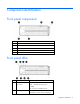
Component identification Front panel components Item Description 1 Server B Power On/Standby button 2 Server B serial label pull tab 3 Server blade release lever 4 Server A serial label pull tab 5 Server A Power On/Standby button Front panel LEDs Item Description Status 1 Server B system power LED Green = On Amber = Standby (auxiliary power available) Off = No power available to server 2 Server B UID LED Blue = Identified Blue flashing = Active remote management Component identificati
Item Description Status Off = No active remote management 3 Server B health LED Green = Normal Flashing = Booting Amber = Degraded condition Red = Critical condition 4 Server B NIC link and activity LED* Green = Network linked Green flashing = Network activity Off = No link or activity 5 Server A NIC link and activity LED* Green = Network linked Green flashing = Network activity Off = No link or activity 6 Server A health LED Green = Normal Flashing = Booting Amber = Degraded condition Red = C
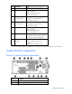
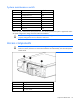
Item Description 3 Server A serial number label 4 System battery 5 Processor socket 1 (populated) 6 Signal connector 7 Mezzanine connector 2 8 Enclosure connector 9 Mezzanine connector 1 10 System maintenance switch 11 DIMM slots (processor 1) 12 Processor socket 2 (populated) 13 Internal USB connector Server B system board components Item Description 1 Hard drive connector 2 Processor socket 1 (populated) 3 System battery 4 DIMM slots (processor 2) 5 Server B serial numb
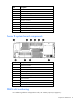
Server A DIMM slots Server B DIMM slots Mezzanine connector definitions Item PCIe support Server support Mezzanine connector 1 x8, Type I mezzanine card only Server A only Mezzanine connector 2 x8, Type 1 mezzanine card only Server B only A PCIe x8 mezzanine connector supports x16 cards at up to x8 speeds.
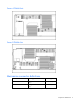
System maintenance switch Position Function Default 1 iLO 2 security override Off 2 Configuration lock Off 3 Reserved Off 4 Reserved Off 5 Password disabled Off 6 Reset configuration Off 7 Reserved Off 8 Reserved Off When the system maintenance switch position 6 is set to the On position, the system is prepared to erase all system configuration settings from both CMOS and NVRAM. CAUTION: Clearing CMOS and/or NVRAM deletes configuration information.
Operations Power up the server blade The Onboard Administrator initiates an automatic power-up sequence when the server blade is installed. If the default setting is changed, use one of the following methods to power up the server blade: • Use an iLO 2 virtual power button selection for server A and server B. • Press and release the server A and server B Power On/Standby button. When the server blade goes from the standby mode to the full power mode, the system power LED changes from amber to green.
Remove the server blade To remove the component: 1. Identify the proper server blade. 2. Power down the server blade (on page 11). 3. Remove the server blade. 4. Place the server blade on a flat, level work surface. WARNING: To reduce the risk of personal injury from hot surfaces, allow the drives and the internal system components to cool before touching them. CAUTION: To prevent damage to electrical components, properly ground the server blade before beginning any installation procedure.
2. Remove the server blade (on page 12). 3. Place the server blade on a flat, level work surface with the bezel facing away from you. CAUTION: The jackscrews control the unseating and seating of critical system connectors. Failure to use the jackscrews to remove and install the server B assembly can cause the system boards to fail. 4. Turn jackscrew 1 approximately six turns counterclockwise. 5. Turn jackscrew 2 counterclockwise until the threads are fully disengaged. 6.
CAUTION: The jackscrews control the unseating and seating of critical system connectors. Failure to use the jackscrews to remove and install the server B assembly can cause the system boards to fail. 4. Engage the threads on jackscrew 1 and tighten six turns clockwise. 5. Engage the threads on jackscrew 2 and tighten fully. 6. Tighten jackscrew 1 fully.
Setup Overview To install a server blade, complete the following steps: 1. Install and configure an HP BladeSystem c-Class enclosure. 2. Install any server blade options. 3. Install interconnect modules in the enclosure. 4. Connect the interconnect modules to the network. 5. Install a server blade. 6. Complete the server blade configuration. Installing an HP BladeSystem c-Class enclosure Before performing any server blade-specific procedures, install an HP BladeSystem c-Class enclosure.
Interconnect bay numbering and device mapping To support network connections for specific signals, install an interconnect module in the bay corresponding to the embedded NIC or mezzanine signals.
1. Remove the device bay blank. 2. Remove the enclosure connector cover. 3. Install the server blade.
Completing the configuration To complete the server blade and HP BladeSystem configuration, see the overview card that ships with the enclosure.
Hardware options installation Introduction If more than one option is being installed, read the installation instructions for all the hardware options and identify similar steps to streamline the installation process. WARNING: To reduce the risk of personal injury from hot surfaces, allow the drives and the internal system components to cool before touching them. CAUTION: To prevent damage to electrical components, properly ground the server before beginning any installation procedure.
o To remove the hard drive carrier from the server A assembly, remove the T-10 hard drive carrier screw and loosen the two system board thumbscrews. Then, slide the system board toward the rear of the enclosure and remove the hard drive carrier. o To remove the hard drive carrier from the server B assembly, remove the T-10 hard drive carrier screw and then remove the hard drive carrier.
6. Prepare the hard drive carrier. 7. Install the hard drive in the carrier. 8.
o To install the hard drive assembly in server A, slide the hard drive assembly into position on the hard drive connector, slide the system board into position in the enclosure, and tighten the system board thumbscrews. Then, install the hard drive carrier retention screw. o To install the hard drive assembly in server B, first slide the hard drive assembly into position on the hard drive connector and then install the hard drive carrier retention screw. 9. If removed, install the USB device. 10.
The memory subsystem in this server blade can support RDIMMs or UDIMMs. Both types are referred to as DIMMs when the information applies to both types. When specified as RDIMM or UDIMM, the information applies to that type only. All memory installed in the server blade must be the same type.
The memory subsystem may be populated with either RDIMMs or UDIMMs, but mixing the two types is not supported. To determine DIMM characteristics, use the label attached to the DIMM and the following illustration and table.
Advanced Memory Protection options are configured in RBSU. If the requested AMP mode is not supported by the installed DIMM configuration, the server blade boots in Advanced ECC mode. For more information, see "HP ROM-Based Setup Utility (on page 37)." For the latest memory configuration information, see the QuickSpecs on the HP website (http://www.hp.com). RDIMM maximum memory configurations The following table lists the maximum memory configuration possible with 16-GB RDIMMs.
• Do not mix Unbuffered and Registered PC3 DIMMs. DIMM speeds are supported as indicated in the following table. Rank Speeds supported (MHz) Single- or dual-rank 1333, 1066 Quad-rank 1066 Advanced ECC population guidelines For Advanced ECC mode configurations, observe the following guidelines: • Observe the general DIMM slot population guidelines (on page 25). • DIMMs may be installed individually.
• In multi-processor configurations, each processor may have a different valid Lockstep Memory configuration. Multi-processor Lockstep population order For Lockstep memory mode configurations with multiple processors, populate DIMM slots A and B for each processor. Do not populate slot C. After installing the DIMMs, use RBSU to configure the system for Lockstep memory support ("Configuring lockstep memory" on page 40).
Optional mezzanine cards provide additional network connectivity or provide either Infini-Band or Fibre Channel support. For mezzanine card locations, see the system board components (on page 7). For mezzanine card signal mapping, see "Interconnect bay numbering and device mapping (on page 16)" and the installation instructions that ship with the server blade.
5. Install the mezzanine card. Press down on the connector to seat the board. 6. Install the server B assembly (on page 13). 7. Install the server blade ("Installing a server blade" on page 16). SD card adapter option The SD card adapter option enables the use of a permanently installed SD card. WARNING: To reduce the risk of personal injury from hot surfaces, allow the drives and the internal system components to cool before touching them. To install the component: 1.
6. Install the server B assembly (on page 13). 7. Install the server blade ("Installing a server blade" on page 16).
Software and configuration utilities Server blade deployment tools Software drivers and additional components HP offers the following additional software components for server blades: • Health and Wellness driver and IML viewer • iLO 2 Management interface driver • Rack infrastructure interface service For Microsoft® Windows® OS users, these items are included in the HP ProLiant iLO 2 Standard Blade Edition, available from the HP website (http://www.hp.com/servers/lights-out).
To connect to the server blade using iLO 2, install the server blade in an enclosure. Onboard Administrator assigns an IP address to enable iLO 2 connectivity to the server blade. The c-Class tab enables you to control specific settings for the HP BladeSystem. iLO 2 also provides webbased status for the HP BladeSystem configuration. For detailed information about iLO 2, refer to the HP Integrated Lights-Out User Guide on the HP website (http://www.hp.com/servers/lights-out).
o TCP/IP networking and an IP address compatible with one of the following: the iLO 2 Diagnostic Port IP address or an assigned DHCP or static IP address o CD-ROM drive, CD/DVD-ROM drive, and/or diskette drive o Any of the following Java™ Runtime Environment versions: 1.3.1_02 1.3.1_07 1.3.1_08 1.4.1 for Windows® users only 1.4.2 for Linux users only Access the Java™ Runtime Environment versions at the HP website (http://java.sun.com/products/archive/index.html).
Deployment methods Four primary deployment methods are supported: IMPORTANT: To deploy a server blade without the RDP, create a bootable diskette or image of a bootable diskette. • PXE deployment (on page 34) • CD-ROM deployment • Diskette image deployment (on page 35) • SAN configuration (on page 36) PXE deployment PXE enables server blades to load an image over the network from a PXE server, and then execute it in memory.
configuration process. This automated server configuration process cuts time from each server deployed, making it possible to scale server deployments to high volumes in a rapid manner. For more information, and to download the SmartStart Scripting Toolkit, refer to the HP website (http://www.hp.com/servers/sstoolkit). CD-ROM deployment CD-ROM deployment involves using a bootable CD that executes scripts to configure the hardware and install the OS.
• iLO virtual floppy (on page 36) • PXE ("PXE deployment" on page 34) Creating a boot diskette The SmartStart Scripting Toolkit provides the tools and information for creating a boot diskette. For details, refer to the SmartStart Scripting Toolkit User Guide and download the latest version of the software from the HP website (http://www.hp.com/servers/sstoolkit). As an alternative method, configure the hardware manually with RBSU and the iLO 2 remote console.
• SAN storage drivers are loaded. Refer to supporting white papers and the HP website (http://www.hp.com/servers/rdp). For SAN configuration information for the server blade, refer to the HP StorageWorks SAN Design Reference Guide on the HP website (http://h18000.www1.hp.com/products/storageworks/san/documentation.html). Configuration tools SmartStart software SmartStart is a collection of software that optimizes single-server setup, providing a simple and consistent way to deploy server configuration.
Using RBSU To use RBSU, use the following keys: • To access RBSU, press the F9 key during power-up when prompted. • To navigate the menu system, use the arrow keys. • To make selections, press the Enter key. • To access Help for a highlighted configuration option, press the F1 key. IMPORTANT: RBSU automatically saves settings when you press the Enter key. The utility does not prompt you for confirmation of settings before you exit the utility.
Boot options Near the end of the boot process, the boot options screen is displayed. This screen is visible for several seconds before the system attempts to boot from a supported boot device. During this time, you can do the following: • Access RBSU by pressing the F9 key. • Access the System Maintenance Menu (which enables you to launch ROM-based Diagnostics or Inspect) by pressing the F10 key. • Force a PXE Network boot by pressing the F12 key.
6. Press the Enter key. 7. Press the Esc key to exit the current menu or press the F10 key to exit RBSU. For more information on mirrored memory, see the white paper on the HP website (http://h18000.www1.hp.com/products/servers/technology/memoryprotection.html). Configuring lockstep memory To configure Lockstep memory: 1. Install the required DIMMs. 2. Access RBSU by pressing the F9 key during power-up when the prompt is displayed. 3. Select System Options. 4. Select Advanced Memory Protection.
• Deleting a logical drive configuration • Setting the controller to be the boot controller If you do not use the utility, ORCA will default to the standard configuration. For more information regarding array controller configuration, refer to the controller user guide. For more information regarding the default configurations that ORCA uses, refer to the HP ROM-Based Setup Utility User Guide on the Documentation CD.
functioning properly, the system periodically resets the timer. However, when the operating system fails, the timer expires and restarts the server. ASR increases server availability by restarting the server within a specified time after a system hang or shutdown. At the same time, the HP SIM console notifies you by sending a message to a designated pager number that ASR has restarted the system. You can disable ASR from the HP SIM console or through RBSU.
StorageWorks library and tape tools HP StorageWorks L&TT provides functionality for firmware downloads, verification of device operation, maintenance procedures, failure analysis, corrective service actions, and some utility functions. It also provides seamless integration with HP hardware support by generating and emailing support tickets that deliver a snapshot of the storage system. For more information, and to download the utility, refer to the StorageWorks L&TT website (http://h18006.www1.hp.
HP ProLiant Essentials Vulnerability and Patch Management Pack The HP ProLiant Essentials Vulnerability and Patch Management Pack software extends the functionality of HP Systems Insight Manager (HP SIM) to provide vulnerability and patch management for target systems. The Vulnerability and Patch Management Pack is an all-in-one vulnerability assessment and patch management tool.
For more information on HP ProLiant Essentials Performance Management Pack, see the documentation available on the HP website (http://www.hp.com/products/pmp). HP Insight Control Environment Suites HP Insight Control Environment and Insight Control Environment for BladeSystem are integrated suites of software that simplify the management of HP infrastructures.
ROM contains the current ROM program version, while the other side of the ROM contains a backup version. NOTE: The server ships with the same version programmed on each side of the ROM. Safety and security benefits When you flash the system ROM, ROMPaq writes over the backup ROM and saves the current ROM as a backup, enabling you to switch easily to the alternate ROM version if the new ROM becomes corrupted for any reason.
HP Insight Diagnostics Online Edition is a web-based application that captures system configuration and other related data needed for effective server blade management. Available in Microsoft® Windows® and Linux versions, the utility helps to ensure proper system operation. For more information or to download the utility, refer to the HP website (http://www.hp.com/servers/diags).
Remote support and analysis tools HP Insight Remote Support software HP Insight Remote Support software delivers secure remote support for your HP Servers and Storage, 24 X 7, so you can spend less time solving problems and more time focused on your business. You can have your systems remotely monitored for hardware failure using secure technology that has been proven at thousands of companies around the world. In many cases, you can avoid problems before they occur.
IMPORTANT: Always perform a backup before installing or updating device drivers. ProLiant Support Packs PSPs represent operating system-specific bundles of ProLiant optimized drivers, utilities, and management agents. Refer to the PSP website (http://h18000.www1.hp.com/products/servers/management/psp.html). Operating system version support Refer to the operating system support matrix (http://www.hp.com/go/supportos).
Change control and proactive notification HP offers Change Control and Proactive Notification to notify customers 30 to 60 days in advance of upcoming hardware and software changes on HP commercial products. For more information, refer to the HP website (http://www.hp.com/go/pcn). Care Pack HP Care Pack Services offer upgraded service levels to extend and expand standard product warranty with easy-to-buy, easy-to-use support packages that help you make the most of your server investments.
Troubleshooting Troubleshooting resources The HP ProLiant Servers Troubleshooting Guide provides procedures for resolving common problems and comprehensive courses of action for fault isolation and identification, error message interpretation, issue resolution, and software maintenance on ProLiant servers and server blades. This guide includes problemspecific flowcharts to help you navigate complex troubleshooting processes. To view the guide, select a language: • English (http://www.hp.
Important safety information Before servicing this product, read the Important Safety Information document provided with the server. Symbols on equipment The following symbols may be placed on equipment to indicate the presence of potentially hazardous conditions. This symbol indicates the presence of hazardous energy circuits or electric shock hazards. Refer all servicing to qualified personnel. WARNING: To reduce the risk of injury from electric shock hazards, do not open this enclosure.
• The full weight of the rack rests on the leveling feet. • The stabilizing feet are attached to the rack if it is a single-rack installation. • The racks are coupled together in multiple-rack installations. • Only one component is extended at a time. A rack may become unstable if more than one component is extended for any reason.
o HP recommends you have access to the SmartStart CD for value-added software and drivers required during the troubleshooting process. Download the current version of SmartStart from the HP website (http://www.hp.com/servers/smartstart). Service notifications To view the latest service notifications, refer to the HP website (http://www.hp.com/go/bizsupport). Select the appropriate server model, and then click the Troubleshoot a Problem link on the product page.
Start diagnosis flowchart Use the following flowchart to start the diagnostic process.
General diagnosis flowchart The General diagnosis flowchart provides a generic approach to troubleshooting. If you are unsure of the problem, or if the other flowcharts do not fix the problem, use the following flowchart. Item See 1 "Symptom information (on page 53)" 2 "Loose connections (on page 54)" 3 "Service notifications (on page 54)" 4 The most recent version of a particular server blade or option firmware is available on the HP Support website (http://www.hp.com/support).
Server blade power-on problems flowchart Symptoms: • The server does not power on. • The system power LED is off or amber.
• The health LED is red or amber. NOTE: For the location of server LEDs and information on their statuses, refer to the server documentation.
POST problems flowchart Symptoms: • Server does not complete POST NOTE: The server has completed POST when the system attempts to access the boot device.
Item Refer to 1 Server blade power-on problems flowchart (on page 57) 2 "POST error messages and beep codes (on page 65)" 3 "Video problems" in the HP ProLiant Servers Troubleshooting Guide located on the Documentation CD or on the HP website (http://www.hp.com/support) 4 "Symptom information (on page 53)" 5 "General memory problems are occurring" in the HP ProLiant Servers Troubleshooting Guide located on the Documentation CD or on the HP website (http://www.hp.
OS boot problems flowchart There are two ways to use SmartStart when diagnosing OS boot problems on a server blade: • Use iLO to attach virtual devices remotely to mount the SmartStart CD on the server blade. • Use an HP c-Class Blade SUV Cable and drive to connect to the server blade, and then restart the server blade.
• Server does not boot SmartStart Possible causes: • Corrupted OS • Hard drive subsystem problem • Incorrect boot order setting in RBSU Item See 1 HP ROM-Based Setup Utility User Guide (http://www.hp.com/servers/smartstart) 2 "POST problems flowchart (on page 59)" 3 • "Hard drive problems" in the HP ProLiant Servers Troubleshooting Guide located on the Documentation CD or on the HP website (http://www.hp.
* See the server blade OS boot problems flowchart (on page 61) Server fault indications flowchart Symptoms: • Server boots, but a fault event is reported by Insight Management Agents (on page 43) • Server boots, but the internal health LED, external health LED, or component health LED is red or amber Troubleshooting 63
NOTE: For the location of server LEDs and information on their statuses, refer to the server documentation. Possible causes: • Improperly seated or faulty internal or external component • Unsupported component installed • Redundancy failure • System overtemperature condition Item See 1 "Management agents (on page 43)" or in the HP ProLiant Servers Troubleshooting Guide located on the Documentation CD or on the HP website (http://www.hp.
POST error messages and beep codes For a complete listing of error messages, refer to the "POST error messages" in the HP ProLiant Servers Troubleshooting Guide located on the Documentation CD or on the HP website (http://www.hp.com/support). WARNING: To avoid potential problems, ALWAYS read the warnings and cautionary information in the server documentation before removing, replacing, reseating, or modifying system components.
Battery replacement HP recommends replacing the battery on both server A and server B when either battery is replaced. If the server blade no longer automatically displays the correct date and time, you may need to replace the battery that provides power to the real-time clock. Under normal use, battery life is 5 to 10 years. WARNING: The computer contains an internal lithium manganese dioxide, a vanadium pentoxide, or an alkaline battery pack.
Regulatory compliance notices Regulatory compliance identification numbers For the purpose of regulatory compliance certifications and identification, this product has been assigned a unique regulatory model number. The regulatory model number can be found on the product nameplate label, along with all required approval markings and information. When requesting compliance information for this product, always refer to this regulatory model number.
to radio communications. However, there is no guarantee that interference will not occur in a particular installation. If this equipment does cause harmful interference to radio or television reception, which can be determined by turning the equipment off and on, the user is encouraged to try to correct the interference by one or more of the following measures: • Reorient or relocate the receiving antenna. • Increase the separation between the equipment and receiver.
Canadian notice (Avis Canadien) Class A equipment This Class A digital apparatus meets all requirements of the Canadian Interference-Causing Equipment Regulations. Cet appareil numérique de la classe A respecte toutes les exigences du Règlement sur le matériel brouilleur du Canada. Class B equipment This Class B digital apparatus meets all requirements of the Canadian Interference-Causing Equipment Regulations.
This symbol on the product or on its packaging indicates that this product must not be disposed of with your other household waste. Instead, it is your responsibility to dispose of your waste equipment by handing it over to a designated collection point for the recycling of waste electrical and electronic equipment.
BSMI notice Chinese notice Class A equipment Korean notice Class A equipment Class B equipment Laser compliance This product may be provided with an optical storage device (that is, CD or DVD drive) and/or fiber optic transceiver. Each of these devices contains a laser that is classified as a Class 1 Laser Product in accordance with US FDA regulations and the IEC 60825-1. The product does not emit hazardous laser radiation. Each laser product complies with 21 CFR 1040.10 and 1040.
other than those specified herein. • Allow only HP Authorized Service technicians to repair the unit. The Center for Devices and Radiological Health (CDRH) of the U.S. Food and Drug Administration implemented regulations for laser products on August 2, 1976. These regulations apply to laser products manufactured from August 1, 1976. Compliance is mandatory for products marketed in the United States.
Electrostatic discharge Preventing electrostatic discharge To prevent damaging the system, be aware of the precautions you need to follow when setting up the system or handling parts. A discharge of static electricity from a finger or other conductor may damage system boards or other static-sensitive devices. This type of damage may reduce the life expectancy of the device. To prevent electrostatic damage: • Avoid hand contact by transporting and storing products in static-safe containers.
Specifications Environmental specifications Specification Value — Temperature range* Operating 10°C to 35°C (50°F to 95°F) Non-operating -30°C to 60°C (-22°F to 140°F) Relative humidity (noncondensing)** — Operating 10% to 90% @ 28°C (82.4°F) Non-operating 5% to 95% @ 38.7°C (101.7°F) Altitude† — Operating 3050 m (10,000 ft) Non-operating 9144 m (30,000 ft) * The following temperature conditions and limitations apply: - All temperature ratings shown are for sea level.
Technical support Before you contact HP Be sure to have the following information available before you call HP: • Technical support registration number (if applicable) • Product serial number • Product model name and number • Product identification number • Applicable error messages • Add-on boards or hardware • Third-party hardware or software • Operating system type and revision level HP contact information For the name of the nearest HP authorized reseller: • See the Contact HP worldwi
• Optional—Parts for which customer self repair is optional. These parts are also designed for customer self repair. If, however, you require that HP replace them for you, there may or may not be additional charges, depending on the type of warranty service designated for your product. NOTE: Some HP parts are not designed for customer self repair. In order to satisfy the customer warranty, HP requires that an authorized service provider replace the part.
Pour plus d'informations sur le programme CSR de HP, contactez votre Mainteneur Agrée local. Pour plus d'informations sur ce programme en Amérique du Nord, consultez le site Web HP (http://www.hp.com/go/selfrepair). Riparazione da parte del cliente Per abbreviare i tempi di riparazione e garantire una maggiore flessibilità nella sostituzione di parti difettose, i prodotti HP sono realizzati con numerosi componenti che possono essere riparati direttamente dal cliente (CSR, Customer Self Repair).
HINWEIS: Einige Teile sind nicht für Customer Self Repair ausgelegt. Um den Garantieanspruch des Kunden zu erfüllen, muss das Teil von einem HP Servicepartner ersetzt werden. Im illustrierten Teilekatalog sind diese Teile mit „No“ bzw. „Nein“ gekennzeichnet. CSR-Teile werden abhängig von der Verfügbarkeit und vom Lieferziel am folgenden Geschäftstag geliefert. Für bestimmte Standorte ist eine Lieferung am selben Tag oder innerhalb von vier Stunden gegen einen Aufpreis verfügbar.
el caso de todas sustituciones que lleve a cabo el cliente, HP se hará cargo de todos los gastos de envío y devolución de componentes y escogerá la empresa de transporte que se utilice para dicho servicio. Para obtener más información acerca del programa de Reparaciones del propio cliente de HP, póngase en contacto con su proveedor de servicios local. Si está interesado en el programa para Norteamérica, visite la página web de HP siguiente (http://www.hp.com/go/selfrepair).
Opcional – Peças cujo reparo feito pelo cliente é opcional. Essas peças também são projetadas para o reparo feito pelo cliente. No entanto, se desejar que a HP as substitua, pode haver ou não a cobrança de taxa adicional, dependendo do tipo de serviço de garantia destinado ao produto. OBSERVAÇÃO: Algumas peças da HP não são projetadas para o reparo feito pelo cliente. A fim de cumprir a garantia do cliente, a HP exige que um técnico autorizado substitua a peça.
Technical support 81
Technical support 82
Acronyms and abbreviations CSR Customer Self Repair DHCP Dynamic Host Configuration Protocol FC Fibre Channel iLO 2 Integrated Lights-Out 2 IML Integrated Management Log NBP Network Bootstrap Program ORCA Option ROM Configuration for Arrays POST Power-On Self Test PXE Preboot Execution Environment RBSU ROM-Based Setup Utility SATA serial ATA SIM Systems Insight Manager Acronyms and abbreviations 83
UID unit identification USB universal serial bus Acronyms and abbreviations 84
Index A access components 10 accessing internal components 12 ACU (Array Configuration Utility) 40 ADU (Array Diagnostic Utility) 47 ASR (Automatic Server Recovery) 41 Automatic Server Recovery (ASR) 41 B battery 72 battery replacement notice 72 beep codes 65 BIOS Serial Console 39 BIOS upgrade 42 BSMI notice 71 buttons 6 C cables 54, 68 Canadian notice 69 Care Pack 50 CD-ROM deployment 35 Change Control 50 Chinese notice 71 components, identification 6 configuration of system 18, 31, 37 configuration too
HP Insight Server Migration Pack software for ProLiant 44 HP ProLiant Essentials Foundation Pack 43 HP ProLiant Essentials Performance Management Pack 44 HP ProLiant Essentials Rapid Deployment Pack 41 HP ProLiant Essentials Virtualization Management Software 43 HP ProLiant Essentials Vulnerability and Patch Management Pack 44 HP Smart Update Manager overview 49 HP Systems Insight Manager overview 43 HP technical support 75 I identification number 67 iLO 2 (Integrated Lights-Out 2) 31, 32, 42 iLO 2 activit
server B assembly, installing 13 server B assembly, removing 12 server blade options, installing 19 server blade release lever 6, 12 server blades, installing 16 server fault indications flowchart 63 server features and options 19 service notifications 54 SmartStart autorun menu 37 SmartStart Scripting Toolkit 34 SmartStart, overview 37 specifications 74 specifications, environmental 74 specifications, server 74 start diagnosis flowchart 55 static electricity 73 StorageWorks Library and Tape Tools (L&TT) 43