
User guide

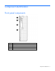

Component identification 9
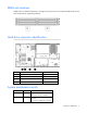
DIMM slot locations
DIMM slots are numbered sequentially (1 through 6) for each processor. The supported AMP modes use the
letter assignments for population guidelines.
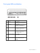
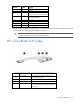
Hard drive connector identification
Item Description Connector color
1
SATA connector 2 Black
2
SATA connector 1 White
3
Hard drive power connector Black
4
Hard drive power connector Black
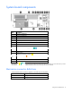
System maintenance switch
Position Default Function
S1
Off Off = iLO 2 security is enabled.
On = iLO 2 security is disabled.
S2
Off Off = System configuration can be
changed.
On = System configuration is locked.