HP ProLiant DL320 Generation 5 Server User Guide Part Number 419196-004 March 2009 (Fourth Edition)
© Copyright 2006, 2009 Hewlett-Packard Development Company, L.P. The information contained herein is subject to change without notice. The only warranties for HP products and services are set forth in the express warranty statements accompanying such products and services. Nothing herein should be construed as constituting an additional warranty. HP shall not be liable for technical or editorial errors or omissions contained herein. Microsoft, Windows, Windows Server, and Windows NT are U.S.
Contents Component identification ............................................................................................................... 7 Front panel components ............................................................................................................................. 7 Front panel LEDs and buttons ...................................................................................................................... 8 Rear panel components.........................................
Installing DIMMs ........................................................................................................................... 30 Hard drive options .................................................................................................................................. 30 Hard drive guidelines..................................................................................................................... 30 Removing a hard drive blank .............................................
Troubleshooting .......................................................................................................................... 65 Troubleshooting resources ........................................................................................................................ 65 Server diagnostic steps ............................................................................................................................ 65 Important safety information.......................................
Acronyms and abbreviations...................................................................................................... 100 Index.......................................................................................................................................
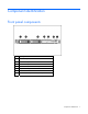
Component identification Front panel components Item Description 1 Serial label pull tab 2 Hard drive bay 1 3 Hard drive bay 2 4 Diskette drive/video connector bay 5 Optical drive bay 6 Front USB connector 7 Power On/Standby button and system power LED Component identification 7
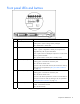
Front panel LEDs and buttons Item Description Status 1 UID button/LED Blue = Identification is activated. Flashing blue = System is being remotely managed. Off = Identification is deactivated. 2 Internal health LED Green = System health is normal. Amber = System is degraded. To identify the component in a degraded state, refer to system board LEDs. Red = System critical. To identify the component in a critical state, refer to system board LEDs. Off = System health is normal (when in standby mode).
Item Description Status 6 Power On/Standby button and system power LED Green = System is on. Amber = System is shut down, but power is still applied. Off = Power cord is not attached, power supply failure has occurred, no power supplies are installed, facility power is not available, or the DC-to-DC converter is not installed.
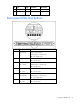
Slot Type Length Connector Interconnect 2 PCI Express Full x8 x8 Optional PCIX Full 133 MHz/3.3 V 64 bit Rear panel LEDs and buttons Item Description Status 1 iLO 2 activity Green = Activity exists. Flashing green = Activity exists. Off = No activity exists. 2 iLO 2 link Green = Link exists. Off = No link exists. 3 10/100/1000 Green = Link exists. NIC 1 activity Flashing green = Activity exists. Off = No link exists. 4 5 10/100/1000 Green = Link exists.
System board components Item Description Item Description 1 PCI Express x8 connector or optional PCI-X 133-MHz connector 13 Diskette drive connector 2 PCI Express x1 connector 14 Fan 3 and 4 connector 3 Video option connector 15 Fan 5 and 6 connector 4 System maintenance switch 16 Fan 7 and 8 connector 5 NMI switch 17 Main power connector 6 Battery 18 Processor socket 7 Hard drive connector 1 19 Auxiliary power connector 8 Hard drive connector 2 20 DIMM slot 1 (bank A) 9
Position Default Function S4 Off Off = Normal operation On = Override RBSU setting and enable diskette boot * S5 Off Off = Power-on password enabled On = Power-on password disabled * S6 Off Off = Normal operation On = BIOS will clear CMOS and NVRAM * S7 Off Reserved S8 Off Reserved * "On" activates the function. NMI functionality An NMI crash dump enables administrators to create crash dump files when a system is hung and not responding to traditional debug mechanisms.
System board LEDs Item LED description Status 1 Reserved — 2 Overtemperature Amber = System has reached a cautionary or critical temperature level. Off = Temperature is OK. 3 Fan 1 and 2 Amber = One or more fans in this module have failed. Off = All fans in this module are operating normally. 4 Processor Amber = Processor has failed. Off = Processor is operating normally. 5 Fan 3 and 4 Amber = One or more fans in this module have failed.
Item LED description Status 10 DIMM 3 Amber = DIMM has failed. Off = DIMM is operating normally. 11 DIMM 2 Amber = DIMM has failed. Off = DIMM is operating normally. 12 DIMM 1 Amber = DIMM has failed. Off = DIMM is operating normally. 13 Power on Green = System board power is normal. Off = System board power has failed. System LEDs and internal health LED combinations When the internal health LED on the front panel illuminates either amber or red, the server is experiencing a health event.
System LED and Color Internal Health LED Color Status Fan module (amber) Amber A redundant fan has failed. Fan module (red) Red The minimum fan requirements are not being met in one or more of the fan modules. One or more fans have failed or are missing. Power supply signal interlock (amber) Red The power supply signal cable is not connected to the system board. Internal USB connector For more information, see "Internal USB functionality (on page 60).
Item Description 1 Device 1 2 Device 2 Fan assembly location Component identification 16
Operations Power up the server To power up the server, press the Power On/Standby button. Power down the server WARNING: To reduce the risk of personal injury, electric shock, or damage to the equipment, remove the power cord to remove power from the server. The front panel Power On/Standby button does not completely shut off system power. Portions of the power supply and some internal circuitry remain active until AC power is removed.
WARNING: To reduce the risk of personal injury or equipment damage, be sure that the rack is adequately stabilized before extending a component from the rack. WARNING: To reduce the risk of personal injury, be careful when pressing the server railrelease latches and sliding the server into the rack. The sliding rails could pinch your fingers. 5. After performing the installation or maintenance procedure: a. Slide the server fully into the rack. b. Secure the server by tightening the thumbscrews. 6.
CAUTION: To prevent damage to the server or expansion boards, power down the server and remove all AC power cords before removing or installing the PCI riser board assembly. 1. Power down the server (on page 17). 2. Extend the server from the rack (on page 17). 3. Remove the access panel (on page 18). 4. Disconnect any internal or external cables connected to any existing expansion boards. 5. Remove the PCI riser board assembly.
2. Install the access panel. 3. Install the server into the rack. Remove the fan assembly 1. Power down the server (on page 17). 2. Extend the server from the rack (on page 17). 3. Remove the access panel (on page 18). 4. Remove the air baffle. 5. Disconnect the fan cables from the system board. 6. Remove the fan assembly.
Install the fan assembly 1. Install the fan assembly. 2. Connect the fan cables to the system board. 3. Install the air baffle. 4. Install the access panel. 5. Install the server into the rack. Remove the BBWC battery holder 1. Remove the screw securing the holder to the chassis.
2. Remove the holder and optional battery and cable, if installed.
Setup Optional installation services Delivered by experienced, certified engineers, HP Care Pack services help you keep your servers up and running with support packages tailored specifically for HP ProLiant systems. HP Care Packs let you integrate both hardware and software support into a single package. A number of service level options are available to meet your needs.
• Leave a minimum clearance of 63.5 cm (25 in) in front of the rack. • Leave a minimum clearance of 76.2 cm (30 in) behind the rack. • Leave a minimum clearance of 121.9 cm (48 in) from the back of the rack to the back of another rack or row of racks. HP servers draw in cool air through the front door and expel warm air through the rear door.
Power requirements Installation of this equipment must comply with local and regional electrical regulations governing the installation of information technology equipment by licensed electricians. This equipment is designed to operate in installations covered by NFPA 70, 1999 Edition (National Electric Code) and NFPA-75, 1992 (code for Protection of Electronic Computer/Data Processing Equipment).
WARNING: To reduce the risk of personal injury or damage to the equipment, be sure that: • The leveling jacks are extended to the floor. • The full weight of the rack rests on the leveling jacks. • The stabilizing feet are attached to the rack if it is a single-rack installation. • The racks are coupled together in multiple-rack installations. • Only one component is extended at a time. A rack may become unstable if more than one component is extended for any reason.
If you are installing the server into a telco rack, order the appropriate option kit at the RackSolutions.com website (http://www.racksolutions.com/hp). Follow the server-specific instructions on the website to install the rack brackets. Use the following information when connecting peripheral cables and power cords to the server. WARNING: To reduce the risk of electric shock, fire, or damage to the equipment, do not plug telephone or telecommunications connectors into RJ-45 connectors.
While the server boots, RBSU and the ORCA utility are automatically configured to prepare the server for OS installation. • Press the F8 key when prompted during the array controller initialization to configure the array controller using ORCA. The array controller defaults to RAID 0 with one drive installed and RAID 1 with more than one drive installed. • Press the F9 key, when prompted during the boot process, to access RBSU and change the server settings (such as language and operating system).
Hardware options installation Memory options The server memory can be expanded by installing PC5300 DDR2 unbuffered SDRAM DIMMs. The server supports up to four ECC DDR2 SDRAM DIMMs. The server supports standard memory configuration for maximum performance with up to 8 GB of active memory (four 2-GB memory modules). Interleaving and non-interleaving memory configuration The server supports interleaving and non-interleaving memory configurations.
Installing DIMMs 1. Power down the server (on page 17). 2. Remove the server from the rack (on page 18). 3. Remove the access panel (on page 18). 4. Open the DIMM slot latches. 5. Install the DIMM. 6. Install the access panel. 7. Install the server into the rack. Hard drive options The server provides non-hot plug capability through an embedded SATA controller. To obtain SAS or SATA hot-plug capability, install an optional controller and hot-plug cable option kit.
NOTE: ACU does not support mixing SAS and SATA drives in the same logical volume. Removing a hard drive blank Remove the component as indicated. CAUTION: To prevent improper cooling and thermal damage, do not operate the server unless all bays are populated with either a component or a blank. Removing hard drives To remove the component: 1. Back up all data on the hard drive. 2. Power down the server (on page 17). 3. Remove the hard drive.
Installing hard drives IMPORTANT: Hot-plug capability and drive LED support are only available when a supported optional controller is installed in the server. 1. Power down the server (on page 17). 2. Remove the existing hard drive blank or hard drive from the drive bay. 3. Prepare the hard drive.
4. Install the hard drive. Optical drive assembly option NOTE: The server supports slimline optical devices, including CD-ROM, DVD-ROM, and DVDRW. 1. Power down the server (on page 17). 2. Remove the server from the rack (on page 18). 3. Remove the access panel (on page 18). 4. Remove the fan assembly (on page 20). 5. Remove the BBWC holder ("Remove the BBWC battery holder" on page 21) and optional battery with cable, if installed. 6. Disconnect the front panel LED board cable. 7.
8. Remove the media cage. 9. Remove the optical drive blank. 10. Remove the screws required to install the optical drive. NOTE: Five screws are provided on the media cage, but only four screws are required to install the drive.
11. Install the optical drive into the media cage.
12. Install the media cage. 13. Connect the optical drive cable and the optical drive power cable to the optical drive. 14. Connect all cables to other devices installed in the media cage, if necessary.
15. Connect the front panel LED board cable. 16. Install the BBWC holder and optional battery with attached cable, if applicable. 17. Install the fan assembly (on page 21). 18. Install the access panel. 19. Install the server into the rack. Diskette drive option CAUTION: To prevent improper cooling and thermal damage, do not operate the server unless all bays are populated with either a component or a blank. 1. Power down the server (on page 17). 2. Remove the server from the rack (on page 18).
6. Disconnect the front panel LED board cable. 7. Disconnect cables from any devices installed in the media cage, if necessary. 8. Remove the media cage.
9. Remove the bay blank or optional video connector. 10. Remove the screws required to install the diskette drive. NOTE: Five screws are provided on the media cage, but only four screws are required to install the drive.
11. Install the diskette drive into the media cage. 12. Install the media cage.
13. Connect the diskette drive cable to the diskette drive. 14. Connect all cables to other devices installed in the media cage, if necessary. 15. Connect the front panel LED board cable. 16. Install the BBWC holder and optional battery with attached cable, if applicable. 17. Install the fan assembly (on page 21). 18. Install the access panel. 19. Install the server into the rack.
2. Remove the server from the rack (on page 18). 3. Remove the access panel (on page 18). 4. Remove the fan assembly (on page 20). 5. Remove the BBWC holder ("Remove the BBWC battery holder" on page 21) and optional battery with cable, if installed. 6. Disconnect the front panel LED board cable. 7. Disconnect cables from any devices installed in the media cage, if necessary. 8. Remove the media cage.
9. Remove the bay blank or optional diskette drive. 10. Remove the screws required to install the top bay option. NOTE: Five screws are provided on the media cage, but only four screws are required to install the option.
11. Install the video connector option into the media cage. 12. Install the media cage.
13. Connect the video cable. 14. Connect all cables to other devices installed in the media cage, if necessary. 15. Connect the front panel LED board cable. 16. Install the BBWC holder and optional battery with attached cable, if applicable. 17. Install the fan assembly (on page 21). 18. Install the access panel. 19. Install the server into the rack. Expansion board 1. Power down the server (on page 17). 2. Remove the server from the rack (on page 18). 3.
4. Disconnect any internal or external cables connected to any existing expansion boards. 5. Remove the PCI riser board assembly (on page 18). 6. Remove the expansion slot cover. 7. Install the expansion board. 8. Install the PCI riser board assembly (on page 19). 9. Install the access panel. 10. Install the server into the rack. PCI riser board option 1. Power down the server (on page 17). 2. Extend the server from the rack, if applicable ("Extend the server from the rack" on page 17). 3.
6. Remove any installed expansion boards. 7. Remove the riser board from the assembly.
8. Install the optional PCI riser board. 9. Install the expansion board (on page 45). 10. Install the PCI riser board assembly (on page 19). IMPORTANT: The server does not power up if the PCI riser board assembly is not seated properly. 11. Install the access panel. 12. Install the server into the rack. Storage controller option IMPORTANT: For additional installation and configuration information, refer to the documentation that ships with the option. 1. Power down the server (on page 17). 2.
9. Connect the HP ProLiant DL320 hot-plug SATA/SAS cable provided in the HP ProLiant DL320 hotplug cable option kit to the storage controller and the backplane. 10. Install the fan assembly (on page 21). 11. Install the access panel. 12. Install the server into the rack.
4. Remove the BBWC battery holder (on page 21). 5. Insert the battery into the holder. 6. Install the battery with holder into the server. 7. Route the cable, and connect the cable to the controller.
Cabling Cabling overview This section provides guidelines that help you make informed decisions about cabling the server and hardware options to optimize performance. Server cable routing CAUTION: When routing cables, always be sure that the cables are not in a position where they can be pinched or air flow can be blocked. IMPORTANT: Route the cables without blocking the airflow or other installed components. Use the cable clips installed in the chassis to manage cable routing.
Optional SAS/SATA controller cable routing CAUTION: When routing cables, always be sure that the cables are not in a position where they can be pinched or air flow can be blocked.
Slot 1 Video connector option cable routing Cabling 53
Battery-backed write cache cable routing Cabling 54
Software and configuration utilities Configuration tools SmartStart software SmartStart is a collection of software that optimizes single-server setup, providing a simple and consistent way to deploy server configuration. SmartStart has been tested on many ProLiant server products, resulting in proven, reliable configurations.
HP ROM-Based Setup Utility RBSU is a configuration utility embedded in ProLiant servers that performs a wide range of configuration activities that can include the following: • Configuring system devices and installed options • Enabling and disabling system features • Displaying system information • Selecting the primary boot controller • Configuring memory options • Language selection For more information on RBSU, see the HP ROM-Based Setup Utility User Guide on the Documentation CD or the HP
NOTE: If the boot drive is not empty or has been written to in the past, ORCA does not automatically configure the array. You must run ORCA to configure the array settings. Drives installed Drives used RAID level 1 1 RAID 0 2 2 RAID 1 3, 4, 5, or 6 3, 4, 5, or 6 RAID 5 More than 6 0 None To change any ORCA default settings and override the auto-configuration process, press the F8 key when prompted. By default, the auto-configuration process configures the system for the English language.
• Remains available any time that the server is on • Displays on-screen tips for individual steps of a configuration procedure For optimum performance, the minimum display settings are 800 × 600 resolution and 256 colors. Servers running Microsoft® operating systems require Internet Explorer 5.5 (with Service Pack 1) or later. For Linux servers, refer to the README.TXT file for additional browser and support information.
functioning properly, the system periodically resets the timer. However, when the operating system fails, the timer expires and restarts the server. ASR increases server availability by restarting the server within a specified time after a system hang or shutdown. At the same time, the HP SIM console notifies you by sending a message to a designated pager number that ASR has restarted the system. You can disable ASR from the HP SIM console or through RBSU.
HP Systems Insight Manager HP SIM is a web-based application that allows system administrators to accomplish normal administrative tasks from any remote location, using a web browser. HP SIM provides device management capabilities that consolidate and integrate management data from HP and third-party devices. IMPORTANT: You must install and use HP SIM to benefit from the Pre-Failure Warranty for processors, SAS and SATA hard drives, and memory modules.
front external USB connectors is not supported. This solution provides for use of a permanent boot drive from a USB drive key installed in the front internal connector, avoiding issues of clearance on the front of the rack and physical access to secure data. For additional security, you can individually disable the front, rear, and internal USB connectors through RBSU. Disabling the rear USB connectors in RBSU disables both rear USB ports.
o For NetWare: IML Viewer o For Windows®: IML Viewer o For Linux: IML Viewer Application • From within the iLO 2 user interface • From within HP Insight Diagnostics (on page 61) For more information, refer to the Management CD in the HP ProLiant Essentials Foundation Pack. Array Diagnostic Utility The HP Array Diagnostics Utility is a web-based application that creates a report of all HP storage controllers and disk drives.
NOTE: If you are installing drivers from the SmartStart CD or the Software Maintenance CD, refer to the SmartStart website (http://www.hp.com/servers/smartstart) to be sure that you are using the latest version of SmartStart. For more information, refer to the documentation provided with the SmartStart CD. If you do not use the SmartStart CD to install an operating system, drivers for some of the new hardware are required.
• Integrates with other software maintenance, deployment, and operating system tools • Automatically checks for hardware, firmware, and operating system dependencies, and installs only the correct ROM upgrades required by each target server To download the tool and for more information, refer to the HP website (http://h18000.www1.hp.com/support/files/index.html).
Troubleshooting Troubleshooting resources The HP ProLiant Servers Troubleshooting Guide provides procedures for resolving common problems and comprehensive courses of action for fault isolation and identification, error message interpretation, issue resolution, and software maintenance on ProLiant servers and server blades. This guide includes problemspecific flowcharts to help you navigate complex troubleshooting processes. To view the guide, select a language: • English (http://www.hp.
Important safety information Before servicing this product, read the Important Safety Information document provided with the server. Symbols on equipment The following symbols may be placed on equipment to indicate the presence of potentially hazardous conditions. This symbol indicates the presence of hazardous energy circuits or electric shock hazards. Refer all servicing to qualified personnel. WARNING: To reduce the risk of injury from electric shock hazards, do not open this enclosure.
WARNING: To reduce the risk of personal injury or damage to the equipment, be sure that: • The leveling feet are extended to the floor. • The full weight of the rack rests on the leveling feet. • The stabilizing feet are attached to the rack if it is a single-rack installation. • The racks are coupled together in multiple-rack installations. • Only one component is extended at a time. A rack may become unstable if more than one component is extended for any reason.
c. Power down the server (on page 17). 5. Disconnect any peripheral devices not required for testing (any devices not necessary to power up the server). Do not disconnect the printer if you want to use it to print error messages. 6. Collect all tools and utilities, such as a Torx screwdriver, loopback adapters, ESD wrist strap, and software utilities, necessary to troubleshoot the problem. o You must have the appropriate Health Drivers and Management Agents installed on the server.
• If a fixed cable tray is available for the server, be sure the cords and cables connected to the server are routed correctly through the tray. • Be sure each device is properly seated. Avoid bending or flexing circuit boards when reseating components. • If a device has latches, be sure they are completely closed and locked. • Check any interlock or interconnect LEDs that may indicate a component is not connected properly.
General diagnosis flowchart The General diagnosis flowchart provides a generic approach to troubleshooting. If you are unsure of the problem, or if the other flowcharts do not fix the problem, use the following flowchart. Item Refer to 1 "Symptom information (on page 68)" 2 "Loose connections (on page 68)" 3 "Service notifications (on page 68)" 4 The most recent version of a particular server or option firmware is available on the HP Support website (http://www.hp.com/support).
Item Refer to 5 "General memory problems are occurring" in the HP ProLiant Servers Troubleshooting Guide located on the Documentation CD or on the HP website (http://www.hp.com/support) 6 Server maintenance and service guide, located on the Documentation CD or the HP website (http://www.hp.com/products/servers/platforms) 7 • Server maintenance and service guide, located on the Documentation CD or the HP website (http://www.hp.
Server power-on problems flowchart Symptoms: • The server does not power on. • The system power LED is off or amber.
• The external health LED is red or amber. • The internal health LED is red or amber. NOTE: For the location of server LEDs and information on their statuses, refer to the server documentation.
Troubleshooting 74
POST problems flowchart Symptoms: • Server does not complete POST NOTE: The server has completed POST when the system attempts to access the boot device.
OS boot problems flowchart Symptoms: • Server does not boot a previously installed operating system • Server does not boot SmartStart Possible causes: • Corrupted operating system • Hard drive subsystem problem • Incorrect boot order setting in RBSU Troubleshooting 76
Item Refer to 1 HP ROM-Based Setup Utility User Guide (http://www.hp.com/servers/smartstart) 2 "POST problems flowchart (on page 75)" 3 • "Hard drive problems" in the HP ProLiant Servers Troubleshooting Guide located on the Documentation CD or on the HP website (http://www.hp.com/support) • Controller documentation 4 "HP Insight Diagnostics (on page 61)" or in the HP ProLiant Servers Troubleshooting Guide located on the Documentation CD or on the HP website (http://www.hp.
Server fault indications flowchart Symptoms: • Server boots, but a fault event is reported by Insight Management Agents (on page 60) • Server boots, but the internal health LED, external health LED, or component health LED is red or amber Troubleshooting 78
NOTE: For the location of server LEDs and information on their statuses, refer to the server documentation. Possible causes: • Improperly seated or faulty internal or external component • Unsupported component installed • Redundancy failure • System overtemperature condition Item Refer to 1 "Management agents (on page 60)" or in the HP ProLiant Servers Troubleshooting Guide located on the Documentation CD or on the HP website (http://www.hp.
POST error messages and beep codes For a complete listing of error messages, refer to the "POST error messages" in the HP ProLiant Servers Troubleshooting Guide located on the Documentation CD or on the HP website (http://www.hp.com/support). WARNING: To avoid potential problems, ALWAYS read the warnings and cautionary information in the server documentation before removing, replacing, reseating, or modifying system components.
Battery replacement If the server no longer automatically displays the correct date and time, you may need to replace the battery that provides power to the real-time clock. Under normal use, battery life is 5 to 10 years. WARNING: The computer contains an internal lithium manganese dioxide, a vanadium pentoxide, or an alkaline battery pack. A risk of fire and burns exists if the battery pack is not properly handled. To reduce the risk of personal injury: • Do not attempt to recharge the battery.
For more information about battery replacement or proper disposal, contact an authorized reseller or an authorized service provider.
Regulatory compliance notices Regulatory compliance identification numbers For the purpose of regulatory compliance certifications and identification, this product has been assigned a unique regulatory model number. The regulatory model number can be found on the product nameplate label, along with all required approval markings and information. When requesting compliance information for this product, always refer to this regulatory model number.
energy and, if not installed and used in accordance with the instructions, may cause harmful interference to radio communications. However, there is no guarantee that interference will not occur in a particular installation.
Canadian notice (Avis Canadien) Class A equipment This Class A digital apparatus meets all requirements of the Canadian Interference-Causing Equipment Regulations. Cet appareil numérique de la classe A respecte toutes les exigences du Règlement sur le matériel brouilleur du Canada. Class B equipment This Class B digital apparatus meets all requirements of the Canadian Interference-Causing Equipment Regulations.
This symbol on the product or on its packaging indicates that this product must not be disposed of with your other household waste. Instead, it is your responsibility to dispose of your waste equipment by handing it over to a designated collection point for the recycling of waste electrical and electronic equipment.
Class B equipment Chinese notice Class A equipment Laser compliance This product may be provided with an optical storage device (that is, CD or DVD drive) and/or fiber optic transceiver. Each of these devices contains a laser that is classified as a Class 1 Laser Product in accordance with US FDA regulations and the IEC 60825-1. The product does not emit hazardous laser radiation. Each laser product complies with 21 CFR 1040.10 and 1040.11 except for deviations pursuant to Laser Notice No.
Batteries, battery packs, and accumulators should not be disposed of together with the general household waste. To forward them to recycling or proper disposal, use the public collection system or return them to HP, an authorized HP Partner, or their agents. For more information about battery replacement or proper disposal, contact an authorized reseller or an authorized service provider.
Electrostatic discharge Preventing electrostatic discharge To prevent damaging the system, be aware of the precautions you need to follow when setting up the system or handling parts. A discharge of static electricity from a finger or other conductor may damage system boards or other static-sensitive devices. This type of damage may reduce the life expectancy of the device. To prevent electrostatic damage: • Avoid hand contact by transporting and storing products in static-safe containers.
Specifications Environmental specifications Specification Value Temperature Operating1 10°C to 35°C (50°F to 90°F) Non-operating 30°C to 60°C (-22°F to 140°F) Maximum rate of temperature change Operating 10°C/hr (18°F/hr) 2,3 Non-operating 20°C/hr (36°F/hr) Relative humidity (noncondensing)*** Operating 10% to 90% Non-operating 5% to 95% Maximum wet bulb temperature (non-condensing) Operating 28°C (82.4°F) Non-operating 38.7°C (101.
Specification Value Width 42.62 cm (16.78 in) Weight (maximum) 12.27 kg (27.0 lb) Weight (no drives installed) 10.91 kg (24.0 lb) Input requirement Rated line voltage 90 VAC to 264 VAC Rated input frequency 47 Hz to 63 Hz Rated input current 6.0 A (100 to 120 VAC) to 3.
Technical support Before you contact HP Be sure to have the following information available before you call HP: • Technical support registration number (if applicable) • Product serial number • Product model name and number • Product identification number • Applicable error messages • Add-on boards or hardware • Third-party hardware or software • Operating system type and revision level HP contact information For the name of the nearest HP authorized reseller: • See the Contact HP worldwi
• Optional—Parts for which customer self repair is optional. These parts are also designed for customer self repair. If, however, you require that HP replace them for you, there may or may not be additional charges, depending on the type of warranty service designated for your product. NOTE: Some HP parts are not designed for customer self repair. In order to satisfy the customer warranty, HP requires that an authorized service provider replace the part.
Pour plus d'informations sur le programme CSR de HP, contactez votre Mainteneur Agrée local. Pour plus d'informations sur ce programme en Amérique du Nord, consultez le site Web HP (http://www.hp.com/go/selfrepair). Riparazione da parte del cliente Per abbreviare i tempi di riparazione e garantire una maggiore flessibilità nella sostituzione di parti difettose, i prodotti HP sono realizzati con numerosi componenti che possono essere riparati direttamente dal cliente (CSR, Customer Self Repair).
HINWEIS: Einige Teile sind nicht für Customer Self Repair ausgelegt. Um den Garantieanspruch des Kunden zu erfüllen, muss das Teil von einem HP Servicepartner ersetzt werden. Im illustrierten Teilekatalog sind diese Teile mit „No“ bzw. „Nein“ gekennzeichnet. CSR-Teile werden abhängig von der Verfügbarkeit und vom Lieferziel am folgenden Geschäftstag geliefert. Für bestimmte Standorte ist eine Lieferung am selben Tag oder innerhalb von vier Stunden gegen einen Aufpreis verfügbar.
el caso de todas sustituciones que lleve a cabo el cliente, HP se hará cargo de todos los gastos de envío y devolución de componentes y escogerá la empresa de transporte que se utilice para dicho servicio. Para obtener más información acerca del programa de Reparaciones del propio cliente de HP, póngase en contacto con su proveedor de servicios local. Si está interesado en el programa para Norteamérica, visite la página web de HP siguiente (http://www.hp.com/go/selfrepair).
• Obrigatória – Peças cujo reparo feito pelo cliente é obrigatório. Se desejar que a HP substitua essas peças, serão cobradas as despesas de transporte e mão-de-obra do serviço. • Opcional – Peças cujo reparo feito pelo cliente é opcional. Essas peças também são projetadas para o reparo feito pelo cliente. No entanto, se desejar que a HP as substitua, pode haver ou não a cobrança de taxa adicional, dependendo do tipo de serviço de garantia destinado ao produto.
Technical support 98
Technical support 99
Acronyms and abbreviations ABEND abnormal end ACU Array Configuration Utility ASR Automatic Server Recovery BIOS Basic Input/Output System DDR double data rate IEC International Electrotechnical Commission iLO Integrated Lights-Out IML Integrated Management Log KVM keyboard, video, and mouse LED light-emitting diode NEMA National Electrical Manufacturers Association NFPA National Fire Protection Association Acronyms and abbreviations 100
NIC network interface controller NMI non-maskable interrupt NVRAM non-volatile memory ORCA Option ROM Configuration for Arrays PCI peripheral component interface PCI Express Peripheral Component Interconnect Express PCI-X peripheral component interconnect extended PDU power distribution unit POST Power-On Self Test PPM processor power module PSP ProLiant Support Pack RAID redundant array of inexpensive (or independent) disks RBSU ROM-Based Setup Utility RDP Rapid Deployment Pack Acronyms and a
ROM read-only memory SAS serial attached SCSI SATA serial ATA SCSI small computer system interface SDRAM synchronous dynamic RAM SIM Systems Insight Manager TMRA recommended ambient operating temperature UID unit identification USB universal serial bus VCA Version Control Agent VCRM Version Control Repository Manager Acronyms and abbreviations 102
Index A ACU (Array Configuration Utility) 57 adapter LEDs 8 additional information 65 ADU (Array Diagnostic Utility) 62 Altiris Deployment Solution 58 Altiris eXpress Deployment Server 58 Array Configuration Utility (ACU) 57 Array Diagnostic Utility (ADU) 62 ASR (Automatic Server Recovery) 58 authorized reseller 92 Automatic Server Recovery (ASR) 58 Autorun menu 55 B battery 11, 12, 81, 87 battery-backed write cache battery holder 21 BIOS Serial Console 57 BIOS upgrade 59 blue screen event 12 boot options
G M general diagnosis flowchart 70 grounding methods 89 grounding requirements 25 Management Agents 60 management tools 58 Manual ROMPaq disastery recovery 62 memory 29, 30 memory dump 12 memory options 29 H hard drive blanks 31 hard drive, replacing 32 hard drives 7, 30, 31, 32 hardware options 29 hardware options installation 26, 29 health driver 58 health LEDs 8, 12 help resources 92 HP Insight Diagnostics 61 HP ProLiant Essentials Foundation Pack 60 HP ProLiant Essentials Rapid Deployment Pack 58 HP
R Systems Insight Manager 60 rack installation 23, 25, 26 rack resources 23 rack stability 66 rack warnings 25, 66 RBSU (ROM-Based Setup Utility) 56 rear panel buttons 10 rear panel LEDs 10 registering the server 28 regulatory compliance notices 83, 85, 88 required information 92 resetting the system 12 RJ-45 network connector LEDs 10 ROMPaq Disaster Recovery 62 ROMPaq utility 59 T S safety considerations 25, 65 SAS device numbers 16 SATA drives 15 scripted installation 55 serial connector 11 serial lab