HP Moonshot 1500 Chassis Setup and Installation Guide Abstract This document contains setup, installation, and configuration information for the HP Moonshot System. This document is for the person who installs, administers, and troubleshoots the HP Moonshot System. HP assumes you are qualified in the servicing of computer equipment and trained in recognizing hazards in products with hazardous energy levels.
© Copyright 2013, 2014 Hewlett-Packard Development Company, L.P. The information contained herein is subject to change without notice. The only warranties for HP products and services are set forth in the express warranty statements accompanying such products and services. Nothing herein should be construed as constituting an additional warranty. HP shall not be liable for technical or editorial errors or omissions contained herein. Microsoft® and Windows® are U.S.
Contents Planning the installation ................................................................................................................. 5 Safety and regulatory compliance .................................................................................................................. 5 Site requirements .......................................................................................................................................... 5 Software prerequisites .............................
Installing network components ........................................................................................................... 29 Cabling the HP Moonshot System ................................................................................................. 36 Cabling overview ....................................................................................................................................... 36 Connecting the Moonshot System to a network ......................................
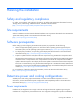
Planning the installation Safety and regulatory compliance For safety, environmental, and regulatory information, see Safety and Compliance Information for Server, Storage, Power, Networking, and Rack Products, available at the HP website (http://www.hp.com/support/Safety-Compliance-EnterpriseProducts).
covered by NFPA 70, 1999 Edition (National Electric Code) and NFPA-75, 1992 (code for Protection of Electronic Computer/Data Processing Equipment). For electrical power ratings on options, refer to the product rating label or the user documentation supplied with that option. WARNING: To reduce the risk of personal injury, fire, or damage to the equipment, do not overload the AC supply branch circuit that provides power to the rack.
WARNING: To reduce the risk of personal injury or damage to the equipment, be sure that: • • • • • The rack is bolted to the floor using the concrete anchor kit. The leveling feet extend to the floor. The full weight of the rack rests on the leveling feet. The racks are coupled together in multiple rack installations. Only one component is extended at a time. If more than one component is extended, a rack might become unstable. WARNING: The chassis is very heavy.
HP rack products draw cool air in through the front and expel warm air through the rear of the enclosure. Therefore, the front of the rack enclosure must be adequately ventilated to enable ambient room air to enter the enclosure, and the rear of the enclosure must be adequately ventilated to enable the warm air to escape from the enclosure. IMPORTANT: Do not block the ventilation openings.
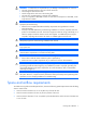
Identifying components and LEDs HP Moonshot System components Item Description 1 HP Moonshot 1500 Chassis 2 Cartridges* 3 Cartridge blank* 4 Access panel 5 Switch module* 6 Fans (5) 7 Uplink module* 8 Moonshot 1500 CM module 9 Power supplies* * The quantity depends on the configuration ordered.
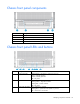
Chassis front panel components Item Description 1 Bezel ear 2 Backplane assembly release lever 3 Serial label pull tab 4 Bezel ear Chassis front panel LEDs and buttons Item Description LED Status 1 Chassis power LED Flashing Green = The chassis is waiting to power on.
Item Description LED Status 4 Cartridge health LEDs Green = Normal operation Amber = Standby mode Flashing Amber = Degraded condition Flashing Amber (All) = Moonshot 1500 CM module is not installed. Flashing Red = Critical condition Off = Cartridge is not installed or no power exists. 5 Switch module A health LED Green = Normal operation Flashing Amber = Degraded condition Flashing Red = Critical condition Off = Switch module is not installed or no power exists.
Fan bay numbering Fan LED Status Description Off The fan is working or the power is off. Solid amber The fan has failed.
Power supply LED Status Description Off • • • Green AC is present and main 12 V output is enabled. No AC power to power supply units. Check the AC power cord. AC is present. Standby output is on; output is disabled.
Item Component Description 1 Serial console port For management 2 SFP+ ports X1–X6 1Gb or 10Gb Ethernet SFP+ ports X1 through X6 support Ethernet traffic only. SFP+ ports support the following pluggable Ethernet transceiver modules: • HP 1000BASE-T SFP • HP 10GBASE-SR SFP+ • HP 10GBASE-DAC SFP+ Any available port can be used to connect to the data center. Ensure the port is populated with supported HP transceiver modules that are compatible with the data center port type.
Moonshot-4QSFP+ Uplink Module components Item Component Description 1 Serial console port For management 2 QSFP+ ports Q1–Q4 40Gb Ethernet QSFP+ ports Q1 through Q4 support Ethernet traffic only. QSFP+ ports support the following pluggable Ethernet transceiver modules: • HP 40GBASE QSFP+ • HP 40GBASE QSFP+ SR4 • HP 40GBASE QSFP+ DAC • HP 40GBASE QSFP+ to 4x10G SFP+ Any available port can be used to connect to the data center.
Item Description Status 1 Uplink module UID LED/button Solid blue = Switch module ID is selected. Flashing blue = Switch module firmware update is in progress. Off = Switch module ID is not selected.
HP Moonshot 1500 Chassis Management module LEDs and buttons Item Description Label 1 iLO CM management port link LED iLO/MGMT 2 iLO CM management port activity LED iLO/MGMT 3 iLO CM link port link LED LINK 4 iLO CM link port activity LED LINK 5 Moonshot 1500 CM module UID LED/button — 6 Moonshot 1500 CM module health LED — Chassis internal components Up to 45 cartridges and two switch modules can be installed in the HP Moonshot 1500 Chassis.
Cartridge slot and switch module bay identification The chassis provides 45 cartridge slots (1-45) and two switch module bays (A-B).
Cartridge LEDs and buttons Item Description Status 1 Cartridge power LED/button Green = Normal operation Amber = Standby operation Off = No power 2 Cartridge health LED Green = Normal operation Flashing amber = Degraded condition Flashing red = Critical condition Off = No power 3 Drive LED* Green = Activity Off = No activity 4 Cartridge UID LED/button Blue = Cartridge ID is selected. Flashing blue = Cartridge firmware update is in progress. Off = Cartridge ID is not selected.
Switch module button, sensor, and LEDs Item Description Status 1 Switch module power Green = Normal operation LED Amber = Standby operation Off = No power 2 Switch module health Green = Normal operation LED Flashing amber = Degraded condition Flashing red = Critical condition Off = No power 3 Switch module uplink Green = Link activity LED Flashing green = Activity Off = No activity 4 Switch module Green = Link downlink activity LED Flashing green = Activity Off = No activity 5 Switch module UID
Installing the chassis Installation overview To set up and install the chassis: 1. Unpack the Moonshot System ("Unpacking the HP Moonshot System" on page 21). 2. Determine the chassis rack spacing ("Determining the chassis rack spacing" on page 21). 3. Install the rack rails ("Installing the rack rails" on page 21). 4. Install the chassis in the rack ("Installing the chassis in the rack" on page 21). 5. Install the blanking panel ("Installing the blanking panel" on page 25). 6.
WARNING: The chassis is very heavy. To reduce the risk of personal injury or damage to the equipment, do the following: • Observe local occupational health and safety requirements and guidelines for manual material handling. • Get help to lift and stabilize the product during installation or removal, especially when the product is not fastened to the rails. The chassis weighs more than 81.65 kg (180.00 lb), so at least four people must lift the chassis into the rack together.
1. Fully extend the rails by pressing the push tabs and extending the rails until the rails click two times. WARNING: To reduce the risk of personal injury or equipment damage, be sure that the rack is adequately stabilized before installing the chassis. WARNING: The chassis is very heavy.
2. Install the chassis into the J-slot on the rails, and then pull it forward. 3. Push in the release lever, and then install the chassis into the rack. CAUTION: Press and hold the "Push" tab on each rail until the chassis begins to slide into the rack. Then, release the "Push" tabs and continue to slide the chassis into the rack. Press and hold the "Push" tab on each rail again when the rails lock at a 76.2-cm (30-inch) extension.
Installing the blanking panel If the rack rail adapter kit is not installed on the rack, always install the blanking panel to ensure proper airflow. The blanking panel is not needed when the rack rail adapter kit is installed. To install the component: 1. For round-hole racks, remove the guide pins and replace them with the guide pins included for round-hole racks.
2. Attach a cage nut to each side of the rack. 3. Align the blanking panel. 4. Secure the blanking panel to the rack. Installing HP Moonshot System components If components were removed during the chassis installation or additional components were ordered, install each device using the procedures in this section.
Maintenance and Service Guide or cartridge-specific user and maintenance guides in the HP Moonshot Information Library (http://www.hp.com/go/moonshot/docs). Installing the Moonshot 1500 CM module Install the component as indicated. Installing a power supply WARNING: To reduce the risk of electric shock or damage to the equipment: • Do not disable the power cord grounding plug. The grounding plug is an important safety feature.
To install the component: Install the power supply into the device bay, and then press firmly until the power supply is seated. Installing the fans Install the component as indicated.
Installing the cartridge To install the component: 1. Prepare the cartridge. 2. Align and install the cartridge into the chassis.
• Always install the switch module and the uplink module in corresponding bays. Both components must be installed for normal operation. • The switch module and the uplink module can be installed in any order. • The switch module and the uplink module power down when either module is removed from the chassis. • The switch module and the uplink module power up after both modules are installed in the chassis.
Production network mapping The first network interface discovered by the operating system routes traffic through switch A. The second network interface discovered by the operating system routes traffic through switch B.
Management network mapping All traffic from the service port management interface is routed through the iLO CM management port. Removing the uplink module blank Remove the component as indicated. Installing the uplink module CAUTION: To avoid connectivity loss, do not remove switches already in operation.
CAUTION: For proper cooling, be sure every switch module bay and uplink module bay has either a blank or a module installed. To install the component: 1. Remove the uplink module bay blank ("Removing the uplink module blank" on page 32). 2. Prepare the uplink module for installation. 3. Install the uplink module. 4. Do one of the following: o If the switch module is already installed, verify the uplink module powers on and the uplink module health LED is green.
To install the component: 1. Locate the switch module slot, and then remove the blank. 2. Prepare the switch module for installation.
3. Align and install the switch module into the chassis. 4. Do one of the following: o If the uplink module is already installed, verify the switch module powers on and the health LED is green. o If the uplink module is not installed, install the uplink module before verifying LEDs. For more information, see "Switch information and guidelines (on page 29)." 5. Install the access panel, and then return the chassis to the rack. 6.
Cabling the HP Moonshot System Cabling overview WARNING: To reduce the risk of electric shock or injury due to high-current electrical energy, be sure that all power is completely disconnected at the source before beginning any power connections to the power bus bars or power bus box. WARNING: Be sure that all circuit breakers are locked in the off position before connecting any power components.
Moonshot iLO CM firmware SSH sessions and switch SSH sessions share connectivity through the iLO CM management port. The iLO CM management port is located on the Moonshot 1500 CM module on the rear of the chassis. Data center production network To connect the chassis to a production network, connect to any available SFP+ or QSFP+ port. The SFP+/QSFP+ ports are located on the uplink module installed in the rear of the chassis.
• Moonshot 4QSFP+ Uplink Module Connecting power cables and applying power to the chassis 1. Connect the power cables to the power supplies. 2. Connect the power cables to the power source (UPS or wall outlet) or to an installed PDU. 3. Wait while the chassis powers on. Power-on events The following power-on events occur after applying power to the chassis: 1. Fans begin operating. 2. iLO starts. 3. Front panel LEDs display the status of initializing components: 4.
Configuring the HP Moonshot System Chassis configuration overview To configure the HP Moonshot System, complete the following: • Configure the chassis (on page 39). • Configure the switch (on page 41). Configure the chassis To configure the Moonshot 1500 chassis, complete the following steps: 1. Connect and configure a terminal for chassis configuration (on page 39). 2. Log in to the iLO CM firmware (on page 40). 3. Obtain the MAC addresses for each cartridge node (on page 40). 4.
Log in to the iLO CM firmware After the terminal session is started, log in as administrator at the login prompt. Enter the username: Administrator Enter the password: password Obtain the management IP address To determine the management IP address for the Moonshot 1500 CM module, log in to the iLO CM firmware while connected to the iLO CM management serial port.
Always use the recommended firmware version for all Moonshot System components. For more information on recommended firmware versions, see the HP website (http://www.hp.com/go/moonshot/download). Updating firmware HP recommends updating the firmware in the following order: • iLO CM firmware • Cartridge firmware • Switch firmware For available firmware updates, see the HP website (http://www.hp.com/go/moonshot/download).
For detailed configuration information, see the Switch Administrator's Guide and Switch CLI Guide in the HP Moonshot Information Library (http://www.hp.com/go/moonshot/docs). Access the CLI locally To access the CLI interface locally: 1. Use a console cable to connect a PC or terminal to the serial console port on the uplink module. 2. Configure the terminal with the following settings: 3. o 115200 baud rate o 8 data bits o No parity o 1 stop bit o No flow control Start the terminal.
enable password {password} Updating the switch firmware using the switch console Use TFTP, SFTP, or SCP to update the switch firmware using the switch console. 1. Connect to the switch console. 2. Log in to the switch. 3. Enter privileged exec mode: enable 4. Verify the version of the current switch image: show bootvar 5. 6. Verify connectivity by pinging the file server: ping x.x.x.x Copy the firmware image from the file server to the alternate firmware bank of the switch: copy tftp://x.x.x.
Power capping The HP Moonshot System provides a power capping feature that operates at the chassis level. The capping feature can be activated using the iLO CM firmware that runs on each HP Moonshot 1500 chassis. After a power cap is set for the chassis, all the resident cartridges in the chassis will have the same uniform power cap applied to them until the cap is either modified or canceled. With HP APM, the enclosure-level power capping feature can be expanded without the need to use the iLO CM firmware.
Example: hpiLO-> show chassis power Chassis: #------Power in use: 170 Watts Power Capacity: 1818 Watts Status: OK Powercap Mode: Max Performance with Redundancy 3.
Troubleshooting Troubleshooting resources The HP Moonshot System Troubleshooting Guide provides procedures for resolving common problems and comprehensive courses of action for fault isolation and identification, issue resolution, and software maintenance on the HP Moonshot System. The document is available in the HP Moonshot Information Library (http://www.hp.com/go/moonshot/docs).
Regulatory information Safety and regulatory compliance For safety, environmental, and regulatory information, see Safety and Compliance Information for Server, Storage, Power, Networking, and Rack Products, available at the HP website (http://www.hp.com/support/Safety-Compliance-EnterpriseProducts). Belarus Kazakhstan Russia marking Manufacturer Hewlett-Packard Company, Address: 3000 Hanover Street, Palo Alto, California 94304, U.S.
Valid date formats include the following: • YWW, where Y indicates the year counting from within each new decade, with 2000 as the starting point. For example, 238: 2 for 2002 and 38 for the week of September 9. In addition, 2010 is indicated by 0, 2011 by 1, 2012 by 2, 2013 by 3, and so forth. • YYWW, where YY indicates the year, using a base year of 2000. For example, 0238: 02 for 2002 and 38 for the week of September 9.
Electrostatic discharge Preventing electrostatic discharge To prevent damaging the system, be aware of the precautions you need to follow when setting up the system or handling parts. A discharge of static electricity from a finger or other conductor may damage system boards or other static-sensitive devices. This type of damage may reduce the life expectancy of the device. To prevent electrostatic damage: • Avoid hand contact by transporting and storing products in static-safe containers.
Specifications Chassis environmental specifications Specification Value Temperature range* — Operating 10°C to 35°C (50°F to 95°F) Non-operating -30°C to 60°C (-22°F to 140°F) Maximum Wet bulb temperature — Operating 28ºC (82.4ºF) Non-operating 38.7ºC (101.7ºF) Relative humidity (non-condensing)** — Operating 10% to 90% Non-operating 5% to 95% * All temperature ratings shown are for sea level. An altitude derating of 1°C per 304.8 m (1.8°F per 1000 ft) to 3048 m (10,000 ft) is applicable.
Support and other resources Before you contact HP Be sure to have the following information available before you call HP: • Technical support registration number (if applicable) • Product name • Chassis serial number • Product identification number • Applicable error messages • Operating system type and revision level To obtain product information, log in to iLO CM firmware and use the Show Chassis Info command.
NOTE: Some HP parts are not designed for customer self repair. In order to satisfy the customer warranty, HP requires that an authorized service provider replace the part. These parts are identified as "No" in the Illustrated Parts Catalog. Based on availability and where geography permits, CSR parts will be shipped for next business day delivery. Same day or four-hour delivery may be offered at an additional charge where geography permits.
Riparazione da parte del cliente Per abbreviare i tempi di riparazione e garantire una maggiore flessibilità nella sostituzione di parti difettose, i prodotti HP sono realizzati con numerosi componenti che possono essere riparati direttamente dal cliente (CSR, Customer Self Repair). Se in fase di diagnostica HP (o un centro di servizi o di assistenza HP) identifica il guasto come riparabile mediante un ricambio CSR, HP lo spedirà direttamente al cliente per la sostituzione.
CSR-Teile werden abhängig von der Verfügbarkeit und vom Lieferziel am folgenden Geschäftstag geliefert. Für bestimmte Standorte ist eine Lieferung am selben Tag oder innerhalb von vier Stunden gegen einen Aufpreis verfügbar. Wenn Sie Hilfe benötigen, können Sie das HP technische Support Center anrufen und sich von einem Mitarbeiter per Telefon helfen lassen. Den Materialien, die mit einem CSR-Ersatzteil geliefert werden, können Sie entnehmen, ob das defekte Teil an HP zurückgeschickt werden muss.
Para obtener más información acerca del programa de Reparaciones del propio cliente de HP, póngase en contacto con su proveedor de servicios local. Si está interesado en el programa para Norteamérica, visite la página web de HP siguiente (http://www.hp.com/go/selfrepair). Customer Self Repair Veel onderdelen in HP producten zijn door de klant zelf te repareren, waardoor de reparatieduur tot een minimum beperkt kan blijven en de flexibiliteit in het vervangen van defecte onderdelen groter is.
Opcional – Peças cujo reparo feito pelo cliente é opcional. Essas peças também são projetadas para o reparo feito pelo cliente. No entanto, se desejar que a HP as substitua, pode haver ou não a cobrança de taxa adicional, dependendo do tipo de serviço de garantia destinado ao produto. OBSERVAÇÃO: Algumas peças da HP não são projetadas para o reparo feito pelo cliente. A fim de cumprir a garantia do cliente, a HP exige que um técnico autorizado substitua a peça.
Support and other resources 57
Support and other resources 58
Acronyms and abbreviations CM chassis management CPLD complex programmable logic device DHCP Dynamic Host Configuration Protocol HP APM HP Advanced Power Manager iLO Integrated Lights-Out PDU power distribution unit QSFP+ enhanced quad small form-factor pluggable SCP Secure Copy Protocol SFP small form-factor pluggable SFP+ enhanced small form-factor pluggable SFTP Secure File Transfer Protocol SSH Secure Shell Acronyms and abbreviations 59
TFTP Trivial File Transfer Protocol UPS uninterruptible power system Acronyms and abbreviations 60
Documentation feedback HP is committed to providing documentation that meets your needs. To help us improve the documentation, send any errors, suggestions, or comments to Documentation Feedback (mailto:docsfeedback@hp.com). Include the document title and part number, version number, or the URL when submitting your feedback.
Index A access panel 9 accessing the CLI 42 activity LED 10 administrator password 40 airflow requirements 7 authorized reseller 51 B backplane assembly release lever 10 battery replacement notice 5 bay numbering, fan 12 bay numbering, power supply 12 bay numbering, uplink module 13 before you contact HP 51 Belarus Kazakhstan Russia marking 47 bezel ear 10 blanking panels 25 BSMI notice 5 C cable management arm 38 cable management arm, installing 38 cabling 36 Canadian notice 5 cartridge blank 9 cartridge
firmware 40, 41, 43 firmware upgrade utility, troubleshooting 46 front panel components 10, 19 J G L grounding methods 49 grounding requirements 8 LED identification 9 LED, cartridge health 19 LED, drive health 19 LED, health 10, 19, 20 LED, link 19 LED, UID 19 LEDs 10, 19, 20 LEDs, front panel 10, 19 LEDs, power supply 13 LEDs, troubleshooting 10, 46 LEDs, unit identification (UID) 10, 20 link LED 19 log in to iLO CM 40 H health LED 10, 17, 20 help resources 51 hot-plug power supply calculations 6 HP
power supply LEDs 13 power supply, installing 27 power up procedure 38 powering up 38 Power-on events 38 preparation procedures 5 prerequisites 5 production network 37 R rack resources 21 rear panel components 11 regulatory compliance identification numbers 5 regulatory compliance information 5, 47 regulatory compliance notices 5, 47 remote management 42 required information 51 requirements, power 5, 6 requirements, site 5 resources 46, 51 RoHS 48 technical support 51 telephone numbers 51 temperature requ