HP ProLiant ML330 G6 Server User Guide Part Number 534305-001 June 2009 (First Edition)
© Copyright 2009 Hewlett-Packard Development Company, L.P. The information contained herein is subject to change without notice. The only warranties for HP products and services are set forth in the express warranty statements accompanying such products and services. Nothing herein should be construed as constituting an additional warranty. HP shall not be liable for technical or editorial errors or omissions contained herein. Microsoft, Windows, and Windows Server are U.S.
Contents Component identification ............................................................................................................... 7 Front panel components ............................................................................................................................. 7 Front panel LEDs and buttons ...................................................................................................................... 8 Rear panel components.........................................
Introduction ............................................................................................................................................ 36 Processor option...................................................................................................................................... 36 Memory options ...................................................................................................................................... 42 Memory subsystem architecture ..................
HP Insight Diagnostics survey functionality ........................................................................................ 83 Integrated Management Log ........................................................................................................... 83 Array Diagnostic Utility .................................................................................................................. 83 HP Insight Server Migration software for ProLiant ..............................................
Preventing electrostatic discharge ............................................................................................................ 111 Grounding methods to prevent electrostatic discharge ................................................................................ 111 Specifications ........................................................................................................................... 112 Environmental specifications ....................................................
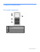
Component identification Front panel components Item Description 1 Optical drive 2 USB connectors (2) 3 Standard hard drive bays (4) 4 Expansion hard drive bays (4) 5 Media bays (2) Component identification 7
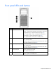
Front panel LEDs and buttons Item Description Status 1 System health LED Green = System health is normal. Amber = System health is degraded. To identify the component in a degraded state, see "System board LEDs (on page 13)." Red = System health is critical. To identify the component in a critical state, see "System board LEDs (on page 13)." Off = System health is normal (when in standby mode). 2 NIC 1 link/activity LED Green or flashing green = Activity exists. Off = No activity exists.
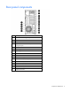
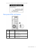
Rear panel components Item Description 1 Dedicated iLO 2 management port 2 Serial connector 3 10/100/1000 NIC 2 4 10/100/1000 NIC 1 connector/shared iLO 2 management port 5 Mouse connector 6 Power supply 1 7 Power supply blank 8 Slot 1 PCI-X* 9 Slot 2 PCI-X* 10 Slot 3 PCIe1 x8 (1) 11 Slot 4 PCIe2 x16 (16, 8, 4, 2, 1) 12 Slot 5 PCIe2 x8 (4, 2, 1) 13 Slot 6 PCI2 x8 (4, 2, 1) 14 Video connector 15 USB connectors (2) 16 Keyboard connector Component identification 9
*Slots 1 and 2 are available only when an optional PCI-X extender board is installed. Rear panel LEDs and buttons Item Description Status 1 UID button/LED Blue = Activated Flashing = System is being managed remotely. Off = Deactivated 2 NIC/iLO 2 activity Green or flashing green = Activity exists. Off = No activity exists. 3 NIC/iLO 2 link Green = Link exists. Off = No link exists.
System board components For this server, some system board slots and connectors are reserved.
Item Description 23 Fan 1 connector 24 Fan 1.5 or 2 connector 25 Fan 3 connector 26 Reserved 27 Processor socket 1 (populated) 28 Battery 29 Reserved 30 Power connector 31 Front USB connector * The server supports one optical drive that can be connected to either SATA connector 5 or SATA connector 6.
NMI functionality An NMI crash dump enables administrators to create crash dump files when a system is hung and not responding to traditional debug mechanisms. Crash dump log analysis is an essential part of diagnosing reliability problems, such as hangs in operating systems, device drivers, and applications. Many crashes freeze a system, and the only available action for administrators is to cycle the system power.
Item LED description Status 4 Overtemperature Amber = System has reached a cautionary or critical temperature level. Off = Normal 5 Fan 1 failure Amber = Fan has failed or is missing. Off = Normal 6 Fan 1.5 or 2 failure Amber = Fan has failed or is missing. Off = Normal 7 DIMM failure (1-9) Amber = DIMM has failed or is missing. Off = Normal 8 Fan 3 failure Amber = Fan has failed or is missing.
System LED and Color Internal Health LED Color Status Overtemperature (amber) Amber The Health Driver has detected a cautionary temperature level. Red The server has detected a hardware critical temperature level. Fan module (amber) Red The minimum fan requirements are not being met in one or more of the fan modules. One or more fans have failed or are missing. Power supply (amber) Red One or more of the following conditions may exist: Amber • There is no AC power.
The memory subsystem may be populated with either RDIMMs or UDIMMs, but mixing the two types is not supported. To determine DIMM characteristics, use the label attached to the DIMM and the following illustration and table.
SAS and SATA device numbers • Standard configuration • Optional configuration with hard drive expansion cage Component identification 17
Hot-plug SATA or SAS hard drive LEDs Item LED description Status 1 Fault/UID status Amber = Drive failure Flashing amber = Fault-process activity Blue = Unit identification is active Off = No fault-process activity 2 Online/Activity status Green = Drive activity Flashing green = High activity on the drive or drive is being configured as part of an array Off = No drive activity The online/activity status LED will not illuminate if using SATA drives connected to the embedded storage device.
Fan locations • Standard fan configuration • Redundant fan configuration Component identification 19
Operations Power up the server To power up the server, press the Power On/Standby button. Power down the server WARNING: To reduce the risk of personal injury, electric shock, or damage to the equipment, remove the power cord to remove power from the server. The front panel Power On/Standby button does not completely shut off system power. Portions of the power supply and some internal circuitry remain active until AC power is removed.
To remove the component: 1. Power down the server (on page 20). 2. Using the key provided with the server, unlock the bezel. 3. Remove the bezel, as needed. Extend the server from the rack NOTE: If the optional cable management arm option is installed, you can extend the server without powering down the server or disconnecting peripheral cables and power cords. These steps are only necessary with the standard cable management solution. 1. Power down the server (on page 20). 2.
o Open or remove the tower bezel, as needed ("Open or remove the tower bezel" on page 20). o Extend the server from the rack (on page 21). 3. Loosen the access panel screws. 4. Slide the access panel back about 1.5 cm (0.5 in). 5. Lift and remove the access panel. CAUTION: For proper cooling, do not operate the server without the access panel, baffles, expansion slot covers, hard drives, or blanks installed. Install the access panel 1.
1. Power down the server (on page 20). 2. Do one of the following: o Open or remove the tower bezel, as needed ("Open or remove the tower bezel" on page 20). o Extend the server from the rack (on page 21). 3. Remove the access panel (on page 21). 4. Remove the air baffle (on page 22). 5. Press and hold the release button. 6. Remove the partition. Remove the media bay blank 1. Power down the server (on page 20). 2.
CAUTION: Always populate each media bay with either a device or a blank. Proper airflow can only be maintained when the bays are populated. Unpopulated drive bays can lead to improper cooling and thermal damage. 3. Remove the media bay blank. Remove a bezel blank 1. Power down the server (on page 20). 2. Remove the front bezel ("Open or remove the tower bezel" on page 20). 3. Remove a bezel blank. Remove the processor board 1. Power down the server (on page 20). 2. Do one of the following: 3.
4. Place the tower server on its side. 5. Remove the air baffle (on page 22). 6. Disconnect the power cable from the processor board. 7. Using a T-15 Torx screwdriver, remove the screws securing the processor board. 8. Remove the processor board. 9. Using the wrench provided in the kit, remove the mezzanine support stand-offs. 10. Remove the metal plate. Install the processor board 1. Power down the server (on page 20). 2.
3. Remove the access panel (on page 21). 4. Place the tower server on its side. 5. Remove the air baffle (on page 22). 6. Using a T-15 Torx screwdriver, remove the seven screws on the system board. Save the screws. 7. Using the wrench provided in the kit, install the seven mezzanine base stand-offs. 8. Install the metal plate on the mezzanine base stand-offs.
9. Using the wrench from the kit, install the mezzanine support stand-offs. 10. Install the processor board. 11. Using the screws removed from the system board, secure the processor board.
Setup Optional installation services Delivered by experienced, certified engineers, HP Care Pack services help you keep your servers up and running with support packages tailored specifically for HP ProLiant systems. HP Care Packs let you integrate both hardware and software support into a single package. A number of service level options are available to meet your needs.
• Leave a minimum clearance of 63.5 cm (25 in) in front of the rack. • Leave a minimum clearance of 76.2 cm (30 in) behind the rack. • Leave a minimum clearance of 121.9 cm (48 in) from the back of the rack to the back of another rack or row of racks. HP servers draw in cool air through the front door and expel warm air through the rear door.
Power requirements Installation of this equipment must comply with local and regional electrical regulations governing the installation of information technology equipment by licensed electricians. This equipment is designed to operate in installations covered by NFPA 70, 1999 Edition (National Electric Code) and NFPA-75, 1992 (code for Protection of Electronic Computer/Data Processing Equipment).
WARNING: To reduce the risk of personal injury or damage to the equipment, be sure that: • The leveling jacks are extended to the floor. • The full weight of the rack rests on the leveling jacks. • The stabilizing feet are attached to the rack if it is a single-rack installation. • The racks are coupled together in multiple-rack installations. • Only one component is extended at a time. A rack may become unstable if more than one component is extended for any reason.
1. Connect peripheral devices to the server ("Rear panel components" on page 9). WARNING: To reduce the risk of electric shock, fire, or damage to the equipment, do not plug telephone or telecommunications connectors into RJ-45 connectors. 2. Connect the power cord to the rear of the server. 3. Connect the power cord to the AC power source. WARNING: To reduce the risk of electric shock or damage to the equipment: • Do not disable the power cord grounding plug.
2. Install the tray onto the rack rails, and then partially slide the assembly into the rack. 3. Attach the straps to the tray. 4. Place the server on the tray, and then secure the server to the tray. CAUTION: To prevent damage to equipment, do not place the monitor on a rack-mounted server. The rack enabling kit supports only the server.
5. Slide the tray fully into the rack, and then tighten the thumbscrews. 6. Slide the locking bracket forward, and then tighten the thumbscrews. Installing the operating system To operate properly, the server must have a supported operating system. For the latest information on supported operating systems, refer to the HP website (http://www.hp.com/go/supportos).
Follow the on-screen instructions to begin the installation process. For information on using these installation paths, refer to the SmartStart installation poster in the HP ProLiant Essentials Foundation Pack, included with the server. Registering the server To register the server, refer to the HP Registration website (http://register.hp.com).
Hardware options installation Introduction If more than one option is being installed, read the installation instructions for all the hardware options and identify similar steps to streamline the installation process. WARNING: To reduce the risk of personal injury from hot surfaces, allow the drives and the internal system components to cool before touching them. CAUTION: To prevent damage to electrical components, properly ground the server before beginning any installation procedure.
CAUTION: To prevent possible server malfunction and damage to the equipment, multiprocessor configurations must contain the same type of processors. IMPORTANT: When installing the heatsink, align the guide pins on the processor retention bracket with the alignment holes in the heatsink. IMPORTANT: Processor socket 1 must always be populated. If processor socket 1 is empty, the server does not power up. NOTE: Do not discard the processor protective cover.
11. Connect an available system power cable to the processor board. 12. Open the processor retaining latch and the processor socket retaining bracket. 13. Remove the processor socket protective cover. IMPORTANT: Be sure the processor remains inside the processor installation tool.
14. If the processor has separated from the installation tool, carefully re-insert the processor in the tool. 15. Align the processor installation tool with the socket and install the processor.
16. Press down firmly until the processor installation tool clicks and separates from the processor, and then remove the processor installation tool. 17. Close the processor socket retaining bracket and the processor retaining latch.
18. Remove the heatsink protective cover. 19. Install the heatsink. Be sure the airflow arrow on the heatsink points toward the rear of the server. 20. (Optional) To optimize performance, install DIMMs into the processor 2 DIMM slots ("Installing DIMMs" on page 46). For the location of the processor 2 DIMM slots, see "System board components (on page 11)." 21. Install the air baffle. 22. Install the access panel (on page 22). 23.
26. Power up the server (on page 20). Memory options IMPORTANT: This server does not support mixing RDIMMs and UDIMMs. Attempting to mix these two types causes the server to halt during BIOS initialization. The memory subsystem in this server can support RDIMMs or UDIMMs. Both types are referred to as DIMMs when the information applies to both types. When specified as RDIMM or UDIMM, the information applies to that type only. All memory installed in the server must be the same type.
one rank accessible at a time. A quad-rank DIMM is, effectively, two dual-rank DIMMs on the same module. Only one rank is accessible at a time. The server memory control subsystem selects the proper rank within the DIMM when writing to or reading from the DIMM. Dual- and quad-rank DIMMs provide the greatest capacity with the existing memory technology. For example, if current DRAM technology supports 2-GB single-rank DIMMs, a dual-rank DIMM would be 4GB, and a quad-rank DIMM would be 8-GB.
Advanced ECC provides additional protection over Standard ECC because it is possible to correct certain memory errors that would otherwise be uncorrected and result in a server failure. The server provides notification that correctable error events have exceeded a pre-defined threshold rate. Lockstep memory configuration Lockstep mode provides protection against multi-bit memory errors that occur on the same DRAM device. Lockstep mode can correct any single DRAM device failure on x4 and x8 DIMM types.
Multi-processor Advanced ECC population order For Advanced ECC mode configurations with multiple processors, populate the DIMM slots for each processor in the following order: • RDIMM: Sequentially in alphabetical order (A through I) • UDIMM: A through F, sequentially in alphabetical order. Do not populate DIMM slots G through I.
• UDIMM o First: A and B o Last: D and E o Do not populate slots C, F, G, H, or I. After installing the DIMMs, use RBSU to configure the system for Lockstep memory support ("Configuring lockstep memory" on page 78). Installing DIMMs CAUTION: To avoid damage to the hard drives, memory, and other system components, the air baffle, drive blanks, and access panel must be installed when the server is powered up. 1. Power down the server (on page 20). 2.
Redundant hot-plug power supply option The server supports a second hot-plug power supply to provide redundant power to the system if the primary power supply fails. WARNING: To reduce the risk of electric shock or damage to the equipment: • Do not disable the power cord grounding plug. The grounding plug is an important safety feature. • Plug the power cord into a grounded (earthed) electrical outlet that is easily accessible at all times.
WARNING: To reduce the risk of injury from electric shock hazards, do not open power supplies. Refer all maintenance, upgrades, and servicing to qualified personnel. CAUTION: Electrostatic discharge (ESD) can damage electronic components. Be sure that you are properly grounded (earthed) before beginning any installation procedure. To install the component: 1. Identify the redundant power supply bay ("Rear panel components" on page 9). IMPORTANT: Power supplies for the model shown are hot-pluggable.
4. Connect the power cord to the power supply. 5. Using the retaining clip shipped with the server, secure the power cord to the power supply handle. Securing the cord will ensure enough slack. 6. Connect the power cord to the AC power source. 7. Be sure that the power supply LED is illuminated green ("Rear panel LEDs and buttons" on page 10). Redundant fan assembly option To install the component: 1. Power down the server (on page 20). 2.
7. Install a fan from the option kit in fan bay 1. 8. Locate the fan 1 connector ("System board components" on page 11). 9. Remove the jumper from the fan 1 connector. 10. Connect the fan cables to the system board ("System board components" on page 11): a. Fan 1 cable to fan 1 connector b. Fan 2 cable to fan 2 connector 11. Install the air baffle. 12. Install the access panel (on page 22). 13. Do one of the following: 14. o Close or install the tower bezel, as needed.
To install the component: 1. Remove the hard drive blank. 2. Prepare the drive for installation.
3. Install the hard drive. 4. Determine the status of the drive by observing the drive LEDs ("Hot-plug SATA or SAS hard drive LEDs" on page 18). 5. Resume normal server operations. Expansion hard drive cage option (hot-plug) To install the component: 1. Power down the server (on page 20). 2. Do one of the following: o Open or remove the tower bezel, as needed ("Open or remove the tower bezel" on page 20). o Extend the server from the rack (on page 21). 3. Remove the access panel (on page 21).
5. Using a T-15 Torx screwdriver, remove the hard drive cage blank. 6. Install the expansion hard drive cage. 7. Connect the following cables to the expansion hard drive cage. a. SATA controller cable b. Hard drive data cable c.
The server is not shown for clarity. 8. Install a SATA RAID controller ("Installing expansion boards" on page 63). 9. Connect the SATA controller cable to the RAID controller. 10. Connect the hard drive data cable to the hard drive backplane connectors on the system board ("System board components" on page 11). CAUTION: To prevent improper cooling and thermal damage, do not operate the server unless all bays are populated with either a component or a blank. 11.
5. Using a T-15 Torx screwdriver, remove the hard drive cage blank. CAUTION: To prevent improper cooling and thermal damage, do not operate the server unless all bays are populated with either a component or a blank. 6. Using four of the surplus T-15 screws located on the non-hot-plug hard drive expansion cage, install the non-hot-plug hard drives. 7. Connect the power and data cables to the non-hot-plug hard drive. 8. Install the non-hot-plug hard drive expansion cage.
Be sure to thread the cables through the rear of the non-hot-plug expansion cage into the server. 9. Connect the cables to the SATA connectors 1-4 on the system board ("System board components" on page 11). 10. Install the air baffle. 11. Install the access panel (on page 22). 12. Do one of the following: 13. o Close or install the tower bezel, as needed. o Slide the server back into the rack. Power up the server (on page 20).
Identifying guide screws When installing drives in the removable media bay, guide screws must be installed so that the drives align correctly in the drive cage. HP has provided extra guide screws, located behind the side access panel. Depending on the option, use 5.25 M3 metric screws or HD 6-32 shipping screws. The metric screws supplied by HP are black. SATA optical drive option For clarity, the following illustrations include option cabling only.
6. Install the guide screws on the optical drive. 7. Install the optical drive. 8. Connect the power cable to the rear of the drive. 9. Connect the optical drive cable to the rear of the optical drive and to the SATA connector on the system board.
10. Remove the applicable bezel blank from the bezel ("Remove a bezel blank" on page 24). 11. Install the access panel (on page 22). 12. Do one of the following: 13. o Close or install the tower bezel, as needed. o Slide the server back into the rack. Power up the server (on page 20). USB tape drive option For clarity, the following illustrations include option cabling only.
7. Install the tape drive. 8. Connect the power cable to the rear of the drive. 9. Connect the USB tape drive cable to the rear of the drive and to the USB tape drive connector on the system board. 10. Remove the applicable bezel blank from the bezel ("Remove a bezel blank" on page 24). 11. Install the access panel (on page 22). 12. Do one of the following: 13. o Close or install the tower bezel, as needed. o Slide the server back into the rack. Power up the server (on page 20).
To install the component: 1. Power down the server (on page 20). 2. Do one of the following: o Unlock and remove the bezel ("Open or remove the tower bezel" on page 20). o Extend the server from the rack (on page 21). 3. Remove the access panel (on page 21). 4. Remove the applicable media bay blanks ("Remove the media bay blank" on page 23). IMPORTANT: For correct cabling, install the full-height tape drive in the top two slots. 5.
10. Connect the tape drive cable to the rear of the drive and to the SAS controller. 11. Remove the applicable bezel blanks from the bezel ("Remove a bezel blank" on page 24). 12. Install the access panel (on page 22). 13. Do one of the following: 14. o Close or install the tower bezel, as needed. o Slide the server back into the rack. Power up the server (on page 20). Expansion board options The server supports PCI Express and PCI-X expansion boards.
3. Remove the access panel (on page 21). 4. Open the slot cover retainer. 5. Remove the slot cover. CAUTION: To prevent improper cooling and thermal damage, do not operate the server unless all PCI slots have either an expansion slot cover or an expansion board installed. Installing expansion boards CAUTION: To prevent damage to the server or expansion boards, power down the server and remove all AC power cords before removing or installing the expansion boards. 1.
o Extend the server from the rack (on page 21). 3. Remove the access panel (on page 21). 4. Remove the expansion slot cover ("Removing the expansion slot cover" on page 62). 5. Install the expansion board, and then press firmly to seat the board in the connector. 6. Close the slot cover retainer. 7. Connect any required internal cables to the expansion board. See the documentation that ships with the expansion board. 8. Install the access panel (on page 22). 9.
7. Remove the protective film from the PCI-X expansion cage bracket. 8. Disconnect the power cable from the extender board. 9. Using a T-10 Torx screwdriver, remove the six screws securing the extender board, and then remove the extender board from the PCI-X expansion cage bracket. 10. Remove fan 3. 11. Install the extender board.
12. Connect the power extender cables, provided in the option kit, to the power cables in the server. For clarity, the following illustration includes cabling only. 13. Install the riser board in expansion slot 5. 14. Connect the mini-SAS data cable to the extender board and to the riser board. 15. (Optional) Install expansion boards in the extender board ("Installing expansion boards" on page 63). 16. Install fan 3. 17. Install the air baffle. 18. Install the access panel (on page 22).
19. Do one of the following: o Close or install the tower bezel, as needed. o Slide the server back into the rack. 20. Connect all power cords to the server. 21. Connect power cords to the power source. 22. Power up the server (on page 20). Storage controller option IMPORTANT: For additional installation and configuration information, refer to the documentation that ships with the option. To install the component: 1. Power down the server (on page 20). 2.
IMPORTANT: The battery pack might have a low charge when installed. In this case, a POST error message is displayed when the server is powered up, indicating that the battery pack is temporarily disabled. No action is necessary on your part. The internal circuitry automatically recharges the batteries and enables the battery pack. This process might take up to four hours. During this time, the cache module functions properly, but without the performance advantage of the battery pack.
7. Connect the cable to the cache module. 8. Install the battery pack. 9. Route the cable. 10. Install the access panel (on page 22). 11. Do one of the following: 12. o Close or install the tower bezel, as needed. o Slide the server back into the rack. Power up the server (on page 20). SAS controller option To install the component: 1. Power down the server (on page 20). 2. Do one of the following: o Open or remove the tower bezel, as needed ("Open or remove the tower bezel" on page 20).
o Extend the server from the rack (on page 21). 3. Remove the access panel (on page 21). 4. Remove the expansion slot cover ("Removing the expansion slot cover" on page 62). 5. Install the SAS controller ("Installing expansion boards" on page 63). 6. Disconnect the SATA cable from the hard drive backplane and from the system board. 7. Connect the SAS cable to the hard drive backplane and to the SAS controller. 8. Install the access panel (on page 22). 9. Do one of the following: 10.
5. Install the dedicated iLO 2 management port module. 6. Using a T-15 Torx screwdriver, secure the dedicated iLO 2 management port module. 7. Install the access panel. 8. Do one of the following: o Close or install the tower bezel, as needed. o Slide the server back into the rack. 9. Connect a network cable to the module, as needed. 10. Power up the server (on page 20). HP Trusted Platform Module option Use these instructions to install and enable a TPM on a supported server.
2. Retaining the recovery key/password (on page 74). 3. Enabling the Trusted Platform Module (on page 74). Enabling the TPM requires accessing the ROM-Based Setup Utility (RBSU) ("HP ROM-Based Setup Utility" on page 76). For more information about RBSU, see the HP website (http://www.hp.com/support/smartstart/documentation). TPM installation requires the use of drive encryption technology, such as the Microsoft® Windows® BitLocker™ Drive Encryption feature.
IMPORTANT: When removing a processor board to install a TPM, the processor, heatsink, and DIMMs can remain installed on the processor board. 5. Remove the processor board, if necessary ("Remove the processor board" on page 24). 6. Locate the TPM connector ("System board components" on page 11). CAUTION: Any attempt to remove an installed TPM from the system board breaks or disfigures the TPM security rivet.
13. o Close or install the tower bezel, as needed. o Slide the server back into the rack. Power up the server (on page 20). Retaining the recovery key/password The recovery key/password is generated during BitLocker™ setup, and can be saved and printed after BitLocker™ is enabled. When using BitLocker™, always retain the recovery key/password. The recovery key/password is required to enter Recovery Mode after BitLocker™ detects a possible compromise of system integrity.
Configuration and utilities Configuration tools SmartStart software SmartStart is a collection of software that optimizes single-server setup, providing a simple and consistent way to deploy server configuration. SmartStart has been tested on many ProLiant server products, resulting in proven, reliable configurations.
Configuration Replication Utility CONREP is shipped in the SmartStart Scripting Toolkit and is a program that works with RBSU to replicate hardware configuration on ProLiant servers. This utility is run during State 0, Run Hardware Configuration Utility, when doing a scripted server deployment. CONREP reads the state of the system environment variables to determine the configuration and then writes the results to an editable script file.
intervention. During this process, the ORCA utility, in most cases, automatically configures the array to a default setting based on the number of drives connected to the server. NOTE: The server may not support all the following examples. NOTE: If the boot drive is not empty or has been written to in the past, ORCA does not automatically configure the array. You must run ORCA to configure the array settings.
3. Select System Options. 4. Select Advanced Memory Protection. 5. Select Mirrored Memory with Advanced ECC Support. 6. Press the Enter key. 7. Press the Esc key to exit the current menu or press the F10 key to exit RBSU. For more information on mirrored memory, see the white paper on the HP website (http://h18000.www1.hp.com/products/servers/technology/memoryprotection.html). Configuring lockstep memory To configure Lockstep memory: 1. Install the required DIMMs ("Installing DIMMs" on page 46).
The utility also provides support for the following functions: • Reconfiguring one or more logical drives • Viewing the current logical drive configuration • Deleting a logical drive configuration • Setting the controller to be the boot controller If you do not use the utility, ORCA will default to the standard configuration. For more information regarding array controller configuration, refer to the controller user guide.
Management tools Automatic Server Recovery ASR is a feature that causes the system to restart when a catastrophic operating system error occurs, such as a blue screen, ABEND, or panic. A system fail-safe timer, the ASR timer, starts when the System Management driver, also known as the Health Driver, is loaded. When the operating system is functioning properly, the system periodically resets the timer. However, when the operating system fails, the timer expires and restarts the server.
CAUTION: Perform a backup before running the System Erase Utility. The utility sets the system to its original factory state, deletes the current hardware configuration information, including array setup and disk partitioning, and erases all connected hard drives completely. Refer to the instructions for using this utility. Run the Erase Utility if you must erase the system for the following reasons: • You want to install a new operating system on a server with an existing operating system.
NOTE: The server ships with the same version programmed on each side of the ROM. Safety and security benefits When you flash the system ROM, ROMPaq writes over the backup ROM and saves the current ROM as a backup, enabling you to switch easily to the alternate ROM version if the new ROM becomes corrupted for any reason. This feature protects the existing ROM version, even if you experience a power failure while flashing the ROM. USB support HP provides both standard USB 2.0 support and legacy USB 2.
For more information or to download the utility, refer to the HP website (http://www.hp.com/servers/diags). HP Insight Diagnostics survey functionality HP Insight Diagnostics (on page 82) provides survey functionality that gathers critical hardware and software information on ProLiant servers. This functionality supports operating systems that may not be supported by the server. For operating systems supported by the server, see the HP website (http://www.hp.com/go/supportos).
SMP automates the migration of the operating system, applications, and data from one server to another without errors, eliminating the need for manual redeployment of these elements on the new server. During the migration process, the software automatically loads new drivers, required for boot, on the destination server. The wizard-based user interface simplifies the migration process and requires little experience or training. For more information about the SMP, see the HP website (http://www.hp.
NOTE: If you are installing drivers from the SmartStart CD or the Software Maintenance CD, refer to the SmartStart website (http://www.hp.com/servers/smartstart) to be sure that you are using the latest version of SmartStart. For more information, refer to the documentation provided with the SmartStart CD. If you do not use the SmartStart CD to install an operating system, drivers for some of the new hardware are required.
Care Pack HP Care Pack Services offer upgraded service levels to extend and expand standard product warranty with easy-to-buy, easy-to-use support packages that help you make the most of your server investments. Refer to the Care Pack website (http://www.hp.com/hps/carepack/servers/cp_proliant.html).
Troubleshooting Troubleshooting resources The HP ProLiant Servers Troubleshooting Guide provides procedures for resolving common problems and comprehensive courses of action for fault isolation and identification, error message interpretation, issue resolution, and software maintenance on ProLiant servers and server blades. This guide includes problemspecific flowcharts to help you navigate complex troubleshooting processes. To view the guide, select a language: • English (http://www.hp.
Important safety information Before servicing this product, read the Important Safety Information document provided with the server. Symbols on equipment The following symbols may be placed on equipment to indicate the presence of potentially hazardous conditions. This symbol indicates the presence of hazardous energy circuits or electric shock hazards. Refer all servicing to qualified personnel. WARNING: To reduce the risk of injury from electric shock hazards, do not open this enclosure.
WARNING: To reduce the risk of personal injury or damage to the equipment, be sure that: • The leveling feet are extended to the floor. • The full weight of the rack rests on the leveling feet. • The stabilizing feet are attached to the rack if it is a single-rack installation. • The racks are coupled together in multiple-rack installations. • Only one component is extended at a time. A rack may become unstable if more than one component is extended for any reason.
To answer these questions, the following information may be useful: • Run HP Insight Diagnostics (on page 82) and use the survey page to view the current configuration or to compare it to previous configurations. • Refer to your hardware and software records for information. • Refer to server LEDs and their statuses. Prepare the server for diagnosis 1. Be sure the server is in the proper operating environment with adequate power, air conditioning, and humidity control.
• If a device has latches, be sure they are completely closed and locked. • Check any interlock or interconnect LEDs that may indicate a component is not connected properly. • If problems continue to occur, remove and reinstall each device, checking the connectors and sockets for bent pins or other damage. Service notifications To view the latest service notifications, refer to the HP website (http://www.hp.com/go/bizsupport).
General diagnosis flowchart The General diagnosis flowchart provides a generic approach to troubleshooting. If you are unsure of the problem, or if the other flowcharts do not fix the problem, use the following flowchart. Item Refer to 1 "Symptom information (on page 89)" 2 "Loose connections (on page 90)" 3 "Service notifications (on page 91)" 4 The most recent version of a particular server or option firmware is available on the HP Support website (http://www.hp.com/support).
Item Refer to 5 "General memory problems are occurring" in the HP ProLiant Servers Troubleshooting Guide located on the Documentation CD or on the HP website (http://www.hp.com/support) 6 Server maintenance and service guide, located on the Documentation CD or the HP website (http://www.hp.com/products/servers/platforms) 7 • Server maintenance and service guide, located on the Documentation CD or the HP website (http://www.hp.
Server power-on problems flowchart Symptoms: • The server does not power on. • The system power LED is off or amber.
• The external health LED is red or amber. • The internal health LED is red or amber. NOTE: For the location of server LEDs and information on their statuses, refer to the server documentation.
Troubleshooting 96
POST problems flowchart Symptoms: • Server does not complete POST NOTE: The server has completed POST when the system attempts to access the boot device.
OS boot problems flowchart Symptoms: • Server does not boot a previously installed operating system • Server does not boot SmartStart Possible causes: • Corrupted operating system • Hard drive subsystem problem • Incorrect boot order setting in RBSU Troubleshooting 98
Item Refer to 1 HP ROM-Based Setup Utility User Guide (http://www.hp.com/servers/smartstart) 2 "POST problems flowchart (on page 97)" 3 • "Hard drive problems" in the HP ProLiant Servers Troubleshooting Guide located on the Documentation CD or on the HP website (http://www.hp.com/support) • Controller documentation 4 "HP Insight Diagnostics (on page 82)" or in the HP ProLiant Servers Troubleshooting Guide located on the Documentation CD or on the HP website (http://www.hp.
Server fault indications flowchart Symptoms: • Server boots, but a fault event is reported by Insight Management Agents (on page 81) • Server boots, but the internal health LED, external health LED, or component health LED is red or amber Troubleshooting 100
NOTE: For the location of server LEDs and information on their statuses, refer to the server documentation. Possible causes: • Improperly seated or faulty internal or external component • Unsupported component installed • Redundancy failure • System overtemperature condition Item Refer to 1 "Management agents (on page 81)" or in the HP ProLiant Servers Troubleshooting Guide located on the Documentation CD or on the HP website (http://www.hp.
POST error messages and beep codes For a complete listing of error messages, refer to the "POST error messages" in the HP ProLiant Servers Troubleshooting Guide located on the Documentation CD or on the HP website (http://www.hp.com/support). WARNING: To avoid potential problems, ALWAYS read the warnings and cautionary information in the server documentation before removing, replacing, reseating, or modifying system components.
Battery replacement If the server no longer automatically displays the correct date and time, you may need to replace the battery that provides power to the real-time clock. Under normal use, battery life is 5 to 10 years. WARNING: The computer contains an internal lithium manganese dioxide, a vanadium pentoxide, or an alkaline battery pack. A risk of fire and burns exists if the battery pack is not properly handled. To reduce the risk of personal injury: • Do not attempt to recharge the battery.
For more information about battery replacement or proper disposal, contact an authorized reseller or an authorized service provider.
Regulatory compliance notices Regulatory compliance identification numbers For the purpose of regulatory compliance certifications and identification, this product has been assigned a unique regulatory model number. The regulatory model number can be found on the product nameplate label, along with all required approval markings and information. When requesting compliance information for this product, always refer to this regulatory model number.
energy and, if not installed and used in accordance with the instructions, may cause harmful interference to radio communications. However, there is no guarantee that interference will not occur in a particular installation.
Canadian notice (Avis Canadien) Class A equipment This Class A digital apparatus meets all requirements of the Canadian Interference-Causing Equipment Regulations. Cet appareil numérique de la classe A respecte toutes les exigences du Règlement sur le matériel brouilleur du Canada. Class B equipment This Class B digital apparatus meets all requirements of the Canadian Interference-Causing Equipment Regulations.
This symbol on the product or on its packaging indicates that this product must not be disposed of with your other household waste. Instead, it is your responsibility to dispose of your waste equipment by handing it over to a designated collection point for the recycling of waste electrical and electronic equipment.
Class B equipment Chinese notice Class A equipment Laser compliance This product may be provided with an optical storage device (that is, CD or DVD drive) and/or fiber optic transceiver. Each of these devices contains a laser that is classified as a Class 1 Laser Product in accordance with US FDA regulations and the IEC 60825-1. The product does not emit hazardous laser radiation. Each laser product complies with 21 CFR 1040.10 and 1040.11 except for deviations pursuant to Laser Notice No.
Batteries, battery packs, and accumulators should not be disposed of together with the general household waste. To forward them to recycling or proper disposal, use the public collection system or return them to HP, an authorized HP Partner, or their agents. For more information about battery replacement or proper disposal, contact an authorized reseller or an authorized service provider.
Electrostatic discharge Preventing electrostatic discharge To prevent damaging the system, be aware of the precautions you need to follow when setting up the system or handling parts. A discharge of static electricity from a finger or other conductor may damage system boards or other static-sensitive devices. This type of damage may reduce the life expectancy of the device. To prevent electrostatic damage: • Avoid hand contact by transporting and storing products in static-safe containers.
Specifications Environmental specifications Specification Value Temperature Operating1 10°C to 35°C (50°F to 90°F) Non-operating 30°C to 60°C (-22°F to 140°F) Maximum rate of temperature change Operating 2,3 Non-operating 10°C/hr (18°F/hr) 20°C/hr (36°F/hr) Relative humidity (noncondensing)*** Operating 10% to 90% Non-operating 5% to 95% Maximum wet bulb temperature (non-condensing) Operating 28°C (82.4°F) Non-operating 38.7°C (101.
Specification Value Weight (no drives installed) 16.04 kg (35.37 lb) Power supply specifications Depending on installed options, the server is configured with one of the following power supplies: • HP ProLiant 750 W Power Supply Specification Value Input requirements Rated input voltage 100 to 120 VAC, 200 to 240 VAC Rated input frequency 50 Hz to 60 Hz Rated input current 9.4 A at 100 VAC 4.
Rated steady-state power 460 W at 100V to 120V AC input 460 W at 200V to 240V AC input Maximum peak power 460 W at 100V to 120V AC input 460 W at 200V to 240V AC input Specifications 114
Technical support Before you contact HP Be sure to have the following information available before you call HP: • Technical support registration number (if applicable) • Product serial number • Product model name and number • Product identification number • Applicable error messages • Add-on boards or hardware • Third-party hardware or software • Operating system type and revision level HP contact information For the name of the nearest HP authorized reseller: • See the Contact HP worldwi
• Optional—Parts for which customer self repair is optional. These parts are also designed for customer self repair. If, however, you require that HP replace them for you, there may or may not be additional charges, depending on the type of warranty service designated for your product. NOTE: Some HP parts are not designed for customer self repair. In order to satisfy the customer warranty, HP requires that an authorized service provider replace the part.
Pour plus d'informations sur le programme CSR de HP, contactez votre Mainteneur Agrée local. Pour plus d'informations sur ce programme en Amérique du Nord, consultez le site Web HP (http://www.hp.com/go/selfrepair). Riparazione da parte del cliente Per abbreviare i tempi di riparazione e garantire una maggiore flessibilità nella sostituzione di parti difettose, i prodotti HP sono realizzati con numerosi componenti che possono essere riparati direttamente dal cliente (CSR, Customer Self Repair).
HINWEIS: Einige Teile sind nicht für Customer Self Repair ausgelegt. Um den Garantieanspruch des Kunden zu erfüllen, muss das Teil von einem HP Servicepartner ersetzt werden. Im illustrierten Teilekatalog sind diese Teile mit „No“ bzw. „Nein“ gekennzeichnet. CSR-Teile werden abhängig von der Verfügbarkeit und vom Lieferziel am folgenden Geschäftstag geliefert. Für bestimmte Standorte ist eine Lieferung am selben Tag oder innerhalb von vier Stunden gegen einen Aufpreis verfügbar.
el caso de todas sustituciones que lleve a cabo el cliente, HP se hará cargo de todos los gastos de envío y devolución de componentes y escogerá la empresa de transporte que se utilice para dicho servicio. Para obtener más información acerca del programa de Reparaciones del propio cliente de HP, póngase en contacto con su proveedor de servicios local. Si está interesado en el programa para Norteamérica, visite la página web de HP siguiente (http://www.hp.com/go/selfrepair).
• Obrigatória – Peças cujo reparo feito pelo cliente é obrigatório. Se desejar que a HP substitua essas peças, serão cobradas as despesas de transporte e mão-de-obra do serviço. • Opcional – Peças cujo reparo feito pelo cliente é opcional. Essas peças também são projetadas para o reparo feito pelo cliente. No entanto, se desejar que a HP as substitua, pode haver ou não a cobrança de taxa adicional, dependendo do tipo de serviço de garantia destinado ao produto.
Technical support 121
Technical support 122
Acronyms and abbreviations ABEND abnormal end ACU Array Configuration Utility ADU Array Diagnostics Utility ASR Automatic Server Recovery BIOS Basic Input/Output System DDR double data rate IEC International Electrotechnical Commission iLO Integrated Lights-Out IML Integrated Management Log KVM keyboard, video, and mouse NEMA National Electrical Manufacturers Association NFPA National Fire Protection Association Acronyms and abbreviations 123
NIC network interface controller NMI non-maskable interrupt NVRAM non-volatile memory ORCA Option ROM Configuration for Arrays PCI peripheral component interface PCI-X peripheral component interconnect extended PCIe peripheral component interconnect express PDU power distribution unit POST Power-On Self Test PSP ProLiant Support Pack RAID redundant array of inexpensive (or independent) disks RBSU ROM-Based Setup Utility RDP Rapid Deployment Pack ROM read-only memory Acronyms and abbreviations
SAS serial attached SCSI SATA serial ATA SCSI small computer system interface SIM Systems Insight Manager SMP Server Migration Pack TPM trusted platform module UID unit identification USB universal serial bus VCA Version Control Agent Acronyms and abbreviations 125
Index A access panel 21, 22 ACU (Array Configuration Utility) 78 additional information 87 ADU (Array Diagnostic Utility) 83 air baffle 22 air baffle, configuring 23 airflow requirements 28, 29 Altiris Deployment Solution 79 Altiris eXpress Deployment Server 79 Array Configuration Utility (ACU) 78 Array Diagnostic Utility (ADU) 83 ASR (Automatic Server Recovery) 80 authorized reseller 115 auto-configuration process 76 Automatic Server Recovery (ASR) 80 Autorun menu 75 B Basic Input/Output System (BIOS) 77,
F fan module locations 19 fans 19, 49 FCC rating label 105 features 7 Federal Communications Commission (FCC) notice 105, 106 flowcharts 91, 92, 94, 97, 98, 100 front bezel 20 front panel buttons 8 front panel components 7 front panel LEDs 8, 14 full-height media device 60 full-height tape drive 60 G general diagnosis flowchart 92 grounding methods 111 grounding requirements 30 guide screws 57 H half-height media device 57, 59 hard drive cage 52, 54 hard drive LEDs 18 hardware options 36 hardware options
P PCI slots 20 PCI-X extender board 64 PCI-X extender board connector 11 phone numbers 115 POST error messages 102 POST problems flowchart 97 power cord 88, 110 power distribution unit (PDU) 30 Power On/Standby button 20 power requirements 30 power supplies 47 power supply configuration 47 powering down 20 powering up 20, 76 power-on problems flowchart 94 pre-diagnostic steps 87 preparation procedures 20, 90 problem diagnosis 87 processor board, installing 26 processor board, removing 24 processors 36 ProLi
Systems Insight Manager 81 T Taiwan battery recycling notice 110 tape drives 59, 60 technical support 115 telephone numbers 115 temperature requirements 29 tower bezel, removing 20 tower server, setting up 31 TPM (Trusted Platform Module) 11, 71, 72 troubleshooting 87 troubleshooting flowcharts 91 troubleshooting resources 87 Trusted Platform Module (TPM) 71, 74 U updating the system ROM 81 UPS (uninterruptible power supply) 30 utilities 75 utilities, deployment 75, 76, 79 V ventilation 28 W warnings 30