HP ProLiant ML350 Generation 5 Server User Guide February 2006 (First Edition) Part Number 405047-001
© Copyright 2006 Hewlett-Packard Development Company, L.P. The information contained herein is subject to change without notice. The only warranties for HP products and services are set forth in the express warranty statements accompanying such products and services. Nothing herein should be construed as constituting an additional warranty. HP shall not be liable for technical or editorial errors or omissions contained herein. Microsoft, Windows, and Windows NT are U.S.
Contents Component identification ............................................................................................................... 6 Front panel components ............................................................................................................................. 6 Front panel LEDs and buttons ...................................................................................................................... 7 Rear panel components..........................................
Removable media device options .............................................................................................................. 38 Accessing the removable media cage .............................................................................................. 38 Identifying guide screws ................................................................................................................. 39 Installing a half-height or full-height media device .......................................
Symptom information ..................................................................................................................... 68 Prepare the server for diagnosis ...................................................................................................... 69 Loose connections ................................................................................................................................... 69 Service notifications..........................................................
Component identification In this section Front panel components ............................................................................................................................ 6 Front panel LEDs and buttons ..................................................................................................................... 7 Rear panel components.............................................................................................................................
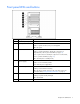
Front panel LEDs and buttons Item Description Status 1 Power On/Standby button — 2 System power LED Green = Power on Amber = System shut down, but power still applied Off = No power 3 Internal health LED Green = Normal Amber = System degraded. To identify the component in a degraded state, refer to system board LEDs (on page 12). Red = System critical. To identify the component in a critical state, refer to system board LEDs (on page 12).
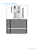
Rear panel components Item Description 1 Video connector 2 Serial connector 3 USB connectors (2) 4 RJ-45 Ethernet connector (iLO 2 management) 5 RJ-45 Ethernet connector (data) 6 PCI Express x8 slots (x4 routed) 7 PCI-X slots (100-MHz) 8 PCI-X slot (133-MHz) 9 Optional redundant hot-plug power supply bay 10 Mouse connector 11 Keyboard connector 12 Power cord connector Component identification 8
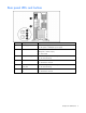
Rear panel LEDs and buttons Item Description Status 1 Power supply LED Green = Power supply is on and functioning Off = No power or inadequate power supply 2 UID LED and button Blue = Activated Flashing blue = Remote inquiry Off = Deactivated 3 iLO 2/data activity LED Green or flashing = Network activity Off = No network activity 4 iLO 2/data link LED Green = Linked to network Off = Not linked to network 5 6 10/100/1000 NIC activity LED Green or flashing = Network activity 10/100/1000 NIC
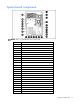
System board components NOTE: PPM 1 is embedded into the system board.
Item Description 25 FBDIMM slots NMI jumper The NMI jumper allows administrators to perform a memory dump before performing a hard reset. Crash dump analysis is an essential part of eliminating reliability problems, such as hangs or crashes in operating systems, device drivers, and applications. Many crashes freeze a system, requiring you to do a hard reset. Resetting the system erases any information that would support root cause analysis.
System board LEDs Item Description Status 1 FBDIMM 1-8 Amber = FBDIMM failed Off = FBDIMM functioning 2 Processor 1 Amber = Processor 1 failed Off = Processor 1 functioning 3 4 Processor 1 fan failure (fan 5) Amber = Fan is not installed or has failed PPM 1 (embedded) Amber = PPM 1 failed Off = Processor fan is functioning Off = PPM 1 functioning 5 Processor 2 Amber = Processor 2 failed Off = Processor 2 functioning 6 AC power Green = Power supply is on and functioning Off = No AC power
Item Description Status 13 System fan 1 Amber = Fan is not installed or has failed Off = Rear fan is functioning 14 Online spare memory Amber = Online spare memory is in use due to memory failover Off = Normal operation 15 Green = System is in online spare memory mode Memory mode Off = Normal operation System LEDs and internal health LED combinations When the internal health LED on the front panel illuminates either amber or red, the server is experiencing a health event.
System LED and color Internal health LED color Status Amber A fan has failed but still meets the minimum fan requirements (with redundant fan option only).
Online/activity LED Fault/UID LED (green) (amber/blue) Interpretation Flashing regularly (1 Hz) Do not remove the drive. Removing a drive may terminate the current operation and cause data loss. Off The drive is rebuilding, or it is part of an array that is undergoing capacity expansion or stripe migration. Flashing irregularly Amber, flashing regularly (1 Hz) The drive is active, but a predictive failure alert has been received for this drive. Replace the drive as soon as possible.
Operations In this section Power up the server ................................................................................................................................ 16 Power down the server............................................................................................................................ 16 Extend the server from the rack ................................................................................................................
WARNING: To reduce the risk of personal injury or equipment damage, be sure that the rack is adequately stabilized before extending a component from the rack. WARNING: To reduce the risk of personal injury, be careful when pressing the server rail-release latches and sliding the server into the rack. The sliding rails could pinch your fingers. 3. After performing the installation or maintenance procedure, press the rail-release latches and slide the server back into the rack.
CAUTION: To avoid breaking the bezel, remove the bezel before placing the server on its side. For operations involving removable media bay access, the media bay panel may be removed from the bezel. Remove the access panel 1. Release the access panel latch. 2. Slide the access panel back about 1.5 cm (0.5 in). 3. Lift and remove the access panel. NOTE: Turn the access panel over to locate the hood labels.
Install the access panel 1. Place the access panel on top of the server, allowing it to extend past the rear of the server approximately 1.5 cm (0.5 in). 2. Slide the access panel forward until it clicks into place, and close the access panel latch.
Setup In this section Optional installation services ................................................................................................................... 20 Optimum environment............................................................................................................................. 21 Rack planning resources ......................................................................................................................... 23 Rack warnings .............................
For more information on Care Packs, refer to the HP website (http://www.hp.com/hps/carepack/servers/cp_proliant.html). Optimum environment When installing the server, select a location that meets the environmental standards described in this section. Space and airflow requirements Tower server In a tower configuration, leave at least a 7.6-cm (3-in) clearance space at the front and back of the server for proper ventilation.
Temperature requirements To ensure continued safe and reliable equipment operation, install or position the system in a wellventilated, climate-controlled environment. The maximum recommended ambient operating temperature (TMRA) for most server products is 35°C (95°F). The temperature in the room where the rack is located must not exceed 35°C (95°F).
Rack planning resources The rack resource kit ships with all HP branded or Compaq branded 9000, 10000, and H9 series racks. For more information on the content of each resource, refer to the rack resource kit documentation. If you intend to deploy and configure multiple servers in a single rack, refer to the white paper on highdensity deployment at the HP website (http://www.hp.com/products/servers/platforms).
The contents of the server shipping carton include: • Server • Power cord • Hardware documentation, Documentation CD, and software products • Rack-mounting hardware In addition to the supplied items, you may need: • T-15 Torx screwdriver • Hardware options • Operating system or application software • PDU Installing hardware options Install any hardware options before initializing the server. For options installation information, refer to the option documentation.
person may be required to help align the server if the server is installed higher than chest level. Use caution when installing the server in or removing the server from the rack; it is unstable when not fastened to the rails. • CAUTION: Always plan the rack installation so that the heaviest item is on the bottom of the rack. Install the heaviest item first, and continue to populate the rack from the bottom to the top. 1. Install the server and cable management arm into the rack.
Installing the operating system To operate properly, the server must have a supported operating system. For the latest information on supported operating systems, refer to the HP website (http://www.hp.com/go/supportos). Two methods are available to install an operating system on the server: • SmartStart assisted installation—Insert the SmartStart CD into the CD-ROM drive and reboot the server. • Manual installation—Insert the operating system CD into the CD-ROM drive and reboot the server.
Hardware options installation In this section Introduction ........................................................................................................................................... 27 Processor option..................................................................................................................................... 27 Memory options .....................................................................................................................................
• Open or remove the tower bezel, as needed ("Open or remove the tower bezel" on page 17). • Extend the server from the rack (on page 16). 3. Remove the access panel (on page 18). 4. Open the processor retaining latch and the processor socket retaining bracket. 5. Remove the processor socket protective cover. IMPORTANT: Be sure the processor remains inside the processor installation tool.
6. If the processor has separated from the installation tool, carefully re-insert the processor in the tool. 7. Align the processor installation tool with the socket and install the processor.
8. Press down firmly until the processor installation tool clicks and separates from the processor, and then remove the processor installation tool. 9. Close the processor socket retaining bracket and the processor retaining latch.
10. Open the heatsink locking levers. 11. Remove the heatsink protective cover.
12. Install the heatsink fan. The heatsink fan points to the rear of the server. 13. Close the heatsink locking levers. 14. Connect the heatsink fan cable to the connector on the system board ("System board components" on page 10).
15. Install the PPM. 16. Close the latches. NOTE: The appearance of compatible PPMs may vary. 17. Install the access panel (on page 19). 18. Do one of the following: • Close or install the tower bezel, as needed. • Slide the server back into the rack. 19. Power up the server (on page 16).
Memory options This server contains eight FBDIMM slots. You can expand server memory by installing supported Registered DDR-2 FBDIMMs. Memory configurations The server supports the following Advanced Memory Protection (AMP) options to optimize server availability. • Advanced ECC supporting up to 16 GB of active memory using 2-GB FBDIMMs.
Online spare memory configuration Online spare memory provides protection against degrading FBDIMMs by reducing the likelihood of uncorrectable memory errors. An understanding of single-rank and dual-rank FBDIMMs is required to understand memory usage in online spare mode. FBDIMMs can either be single-rank or dual-rank. Certain FBDIMM configuration requirements are based on these classifications. A dual-rank FBDIMM is similar to having two separate FBDIMMs, or ranks, on the same module.
7. Install the FBDIMM. 8. Install the air baffle. 9. Install the access panel (on page 19). 10. If you are installing FBDIMMs in an online spare or mirrored configuration, use RBSU to configure this feature. Hard drive options Hard drive blank To remove a hard drive blank: 1. Open the bezel (tower model) 2. Squeeze the tabs to release the blank, and pull the blank out.
CAUTION: To prevent improper cooling and thermal damage, do not operate the server unless all bays are populated with either a component or a blank. NOTE: Depending on model purchased, the server may look slightly different than shown. SATA or SAS hard drive To install the component: 1. Open the bezel (tower model) 2. Remove the existing hard drive blank (on page 36). 3. Open the release latch to prepare the drive for installation.
4. Install the drive. NOTE: Depending on model purchased, the server may look slightly different than shown. 5. Determine the status of the drive by observing the drive LEDs ("SAS and SATA hard drive LEDs" on page 14). 6. Close the bezel (tower model). 7. Resume normal server operations. Removable media device options Accessing the removable media cage The server supports installation of optional internal storage devices. To access the components: 1. Power down the server (on page 16). 2.
4. Remove the media bay blank. 5. Install other hardware options as needed. 6. Install the access panel (on page 19). 7. Do one of the following: • Close or install the tower bezel, as needed. • Slide the server back into the rack. Identifying guide screws When installing drives in the removable media bay, guide screws must be installed to make sure the drives correctly align in the drive cage. HP has provided extra guide screws, located behind the side access panel.
Installing a half-height or full-height media device The server includes five removable media bays. The server ships with an IDE CD-ROM drive and the other four bays are vacant. You can install two full-height removable or up to four half-height media devices in the removable media cage. To install a half-height or full-height media device: 1. Power down the server (on page 16). 2. Do one of the following: • Open or remove the tower bezel, as needed ("Open or remove the tower bezel" on page 17).
7. (Optional) When shipping a server with a full-height device installed, replace the front guide screw with a shipping screw ("Installing the full-height media device shipping screw" on page 41). 8. Connect the data and power cables to the rear of the device. 9. Install the access panel (on page 19). 10. Do one of the following: • Close or install the tower bezel, as needed. • Slide the server back into the rack.
3. Install the silver shipping screw into the full-height device. Installing a diskette drive 1. Power down the server (on page 16). 2. Do one of the following: • Open or remove the tower bezel, as needed ("Open or remove the tower bezel" on page 17). • Extend the server from the rack (on page 16). 3. Remove the media bay blank ("Accessing the removable media cage" on page 38). 4. Remove the access panel (on page 18). 5.
7. Slide the diskette drive into the diskette drive bay. 8. Connect the data and power cables to the rear of the device. 9. Connect the diskette drive cable to the diskette drive cable connector on the system board ("System board components" on page 10). 10. Install the access panel (on page 19). 11. Do one of the following: • Close or install the tower bezel, as needed. • Slide the server back into the rack. 12. Power up the server (on page 16).
2. Remove the power supply blank. WARNING: To reduce the risk of electric shock or damage to the equipment, do not connect AC power cords to uninstalled power supplies. 3. Slide the power supply into the power supply bay until the release/lock lever clicks, securing the power supply. 4. Using the retaining clip shipped with the server, secure the power cord to the power supply handle. Securing the cord will ensure enough slack. 5. Connect the power cord to the power supply. 6.
Removing the expansion slot cover To install the component: 1. Power down the server (on page 16). 2. Do one of the following: • Open or remove the tower bezel, as needed ("Open or remove the tower bezel" on page 17). • Extend the server from the rack (on page 16). 3. Remove the access panel (on page 18). 4. Push the release latches on the expansion board retainer and pull the retainer out away from the chassis. 5. Remove the expansion slot cover.
Installing an expansion board CAUTION: To prevent damage to the server or expansion boards, power down the server and remove all AC power cords before removing or installing the expansion boards. 1. Power down the server (on page 16). 2. Do one of the following: • Open or remove the tower bezel, as needed ("Open or remove the tower bezel" on page 17). • Extend the server from the rack (on page 16). 3. Remove the access panel (on page 18). 4.
PCI-X video cards must be installed in slots 2 or 3 only. 7. Close the expansion slot latch to secure the board. 8. Connect any required internal cables to the expansion board. Refer to the documentation that ships with the expansion board. 9. Install the expansion board retainer. 10. Install the access panel (on page 19). 11. Do one of the following: • Close or install the tower bezel, as needed. • Slide the server back into the rack. 12.
6. Connect the parallel and serial cables to the parallel and serial connectors on the system board. 7. Install the access panel (on page 19). 8. Do one of the following: 9. • Close or install the tower bezel, as needed. • Slide the server back into the rack. Power up the server (on page 16). 10. Enable the feature under the System Options menu in RBSU. For more information on RBSU, refer to the HP ROM-Based Setup Utility User Guide on the Documentation CD or the HP website (http://www.hp.
4. Remove the air baffle. 5. Install the redundant fan assembly, making sure the fans click into place.
NOTE: The fan configuration is redundant only when both fans are installed. 6. Connect the redundant fan cables to the redundant fan connectors on the system board ("System board components" on page 10). 7. Install the air baffle. 8. Install the access panel (on page 19). 9. Do one of the following: • Close or install the tower bezel, as needed. • Slide the server back into the rack. 10. Power up the server (on page 16).
• 128 MB supports RAID 0, 1, 5, and 10 CAUTION: To prevent a server malfunction or damage to the equipment, do not add or remove the battery pack while an array capacity expansion, RAID level migration, or stripe size migration is in progress. IMPORTANT: The battery pack might have a low charge when installed. In this case, a POST error message is displayed when the server is powered up, indicating that the battery pack is temporarily disabled. No action is necessary on your part.
The tower-to-rack conversion kit includes: • Rack rails • Cable management arm • Server rails • Cage nuts • Rack bezel In addition to the supplied items, you may need: • T-10 Torx screwdriver • T-15 Torx screwdriver • Cable management arm extender bracket, included with the server To convert a tower server to a rack server: 1. Power down the server (on page 16). 2. Remove the tower bezel ("Open or remove the tower bezel" on page 17). 3. Remove the feet. 4.
Use the T-10 Torx screwdriver to remove the front panel screws. Unhook the tower configuration panels from the chassis, then slide them back and away from the chassis. 5. Remove the access panel (on page 18).
6. Align the pins on the rack bezel with the corresponding slots on the chassis, and secure the rack bezel to the chassis using the screws inside the chassis. 7. Install the access panel (on page 19). 8. Install the server into the rack ("Installing the server into the rack" on page 24).
Cabling In this section Optional SATA or SAS cabling ................................................................................................................ 55 Standard SATA cabling .......................................................................................................................... 55 Optional ATA or ATAPI device cabling .....................................................................................................
connectors. If only one IDE device is connected to the system, it must be secured to the cable connector labeled Drive 0. For all IDE devices, set the configuration jumpers to "Cable Select" or "CS." IMPORTANT: If the network operating system is Novell NetWare, HP recommends that you connect the CD-ROM to the primary IDE channel and to the Drive 0 connector on the IDE cable. NOTE: ATA (IDE) hard drives are not supported.
Software and configuration utilities In this section Configuration tools ................................................................................................................................. 57 Management tools.................................................................................................................................. 60 Diagnostic tools .....................................................................................................................................
Configuration Replication Utility ConRep is shipped in the SmartStart Scripting Toolkit and is a program that works with RBSU to replicate hardware configuration on ProLiant servers. This utility is run during State 0, Run Hardware Configuration Utility, when doing a scripted server deployment. ConRep reads the state of the system environment variables to determine the configuration and then writes the results to an editable script file.
To change any ORCA default settings and override the auto-configuration process, press the F8 key when prompted. By default, the auto-configuration process configures the system for the English language. To change any default settings in the auto-configuration process (such as the settings for language, operating system, and primary boot controller), execute RBSU by pressing the F9 key when prompted. After the settings are selected, exit RBSU and allow the server to reboot automatically.
The utility also provides support for the following functions: • Reconfiguring one or more logical drives • Viewing the current logical drive configuration • Deleting a logical drive configuration • Setting the controller to be the boot controller If you do not use the utility, ORCA will default to the standard configuration. For more information regarding array controller configuration, refer to the controller user guide.
functioning properly, the system periodically resets the timer. However, when the operating system fails, the timer expires and restarts the server. ASR increases server availability by restarting the server within a specified time after a system hang or shutdown. At the same time, the HP SIM console notifies you by sending a message to a designated pager number that ASR has restarted the system. You can disable ASR from the HP SIM console or through RBSU.
Erase Utility CAUTION: Perform a backup before running the System Erase Utility. The utility sets the system to its original factory state, deletes the current hardware configuration information, including array setup and disk partitioning, and erases all connected hard drives completely. Refer to the instructions for using this utility.
Access to redundant ROM settings To access the redundant ROM through RBSU: 1. Access RBSU by pressing the F9 key during powerup when the prompt is displayed in the upper right corner of the screen. 2. Select Advanced Options. 3. Select Redundant ROM Selection. 4. Select the ROM version. 5. Press the Enter key. 6. Press the Esc key to exit the current menu or press the F10 key to exit RBSU. The server restarts automatically. To access the redundant ROM manually: 1.
Diagnostic tools Array Diagnostic Utility ADU is a tool that collects information about array controllers and generates a list of detected problems. ADU can be accessed from the SmartStart CD ("SmartStart software" on page 57) or downloaded from the HP website (http://www.hp.com).
NOTE: If you are installing drivers from the SmartStart CD, be sure that you are using the latest version of SmartStart by visiting the SmartStart website (http://www.hp.com/servers/smartstart). For more information, refer to the documentation provided with the SmartStart CD. If you do not use the SmartStart CD to install an operating system, drivers for some of the new hardware are required.
Troubleshooting In this section Troubleshooting resources ....................................................................................................................... 66 Pre-diagnostic steps ................................................................................................................................ 66 Loose connections .................................................................................................................................. 69 Service notifications.....
Important safety information Before servicing this product, read the Important Safety Information document provided with the server. Symbols on equipment The following symbols may be placed on equipment to indicate the presence of potentially hazardous conditions. This symbol indicates the presence of hazardous energy circuits or electric shock hazards. Refer all servicing to qualified personnel. WARNING: To reduce the risk of injury from electric shock hazards, do not open this enclosure.
WARNING: To reduce the risk of personal injury or damage to the equipment, be sure that: • The leveling feet are extended to the floor. • The full weight of the rack rests on the leveling feet. • The stabilizing feet are attached to the rack if it is a single-rack installation. • The racks are coupled together in multiple-rack installations. • Only one component is extended at a time. A rack may become unstable if more than one component is extended for any reason.
Prepare the server for diagnosis 1. Be sure the server is in the proper operating environment with adequate power, air conditioning, and humidity control. Refer to the server documentation for required environmental conditions. 2. Record any error messages displayed by the system. 3. Remove all diskettes and CDs from the media drives. 4. Power down the server and peripheral devices if you will be diagnosing the server offline. Always perform an orderly shutdown, if possible. This means you must: a.
Troubleshooting flowcharts To effectively troubleshoot a problem, HP recommends that you start with the first flowchart in this section, "Start diagnosis flowchart (on page 70)," and follow the appropriate diagnostic path. If the other flowcharts do not provide a troubleshooting solution, follow the diagnostic steps in "General diagnosis flowchart (on page 71).
General diagnosis flowchart The General diagnosis flowchart provides a generic approach to troubleshooting. If you are unsure of the problem, or if the other flowcharts do not fix the problem, use the following flowchart.
Item Refer to 4 The most recent version of a particular server or option firmware is available on the following websites: • HP Support website (http://www.hp.com/support) • HP ROM-BIOS/Firmware Updates website (http://h18023.www1.hp.com/support/files/server/us/romflash.ht ml) 5 "General memory problems are occurring" in the HP ProLiant Servers Troubleshooting Guide located on the Documentation CD or on the HP website (http://www.hp.
Server power-on problems flowchart Symptoms: • The server does not power on. • The system power LED is off or amber. • The external health LED is red or amber.
• The internal health LED is red or amber. NOTE: For the location of server LEDs and information on their statuses, refer to the server documentation.
Troubleshooting 75
POST problems flowchart Symptoms: • Server does not complete POST NOTE: The server has completed POST when the system attempts to access the boot device.
OS boot problems flowchart Symptoms: • Server does not boot a previously installed operating system • Server does not boot SmartStart Possible causes: • Corrupted operating system • Hard drive subsystem problem • Incorrect boot order setting in RBSU Troubleshooting 77
Item Refer to 1 HP ROM-Based Setup Utility User Guide (http://www.hp.com/servers/smartstart) 2 "POST problems flowchart (on page 76)" 3 • "Hard drive problems" in the HP ProLiant Servers Troubleshooting Guide located on the Documentation CD or on the HP website (http://www.hp.com/support) • Controller documentation 4 "HP Insight Diagnostics (on page 64)" or in the HP ProLiant Servers Troubleshooting Guide located on the Documentation CD or on the HP website (http://www.hp.
Server fault indications flowchart Symptoms: • Server boots, but a fault event is reported by Insight Management Agents (on page 62) • Server boots, but the internal health LED, external health LED, or component health LED is red or amber NOTE: For the location of server LEDs and information on their statuses, refer to the server documentation.
Possible causes: • Improperly seated or faulty internal or external component • Unsupported component installed • Redundancy failure • System overtemperature condition Item Refer to 1 "Management agents (on page 62)" or in the HP ProLiant Servers Troubleshooting Guide located on the Documentation CD or on the HP website (http://www.hp.
POST error messages and beep codes Introduction to POST error messages The error messages and codes in this section include all new messages generated by this server. Some messages are informational and do not indicate an error. A server generates only the codes that are applicable to its configuration and options.
For a complete listing of error messages, refer to the "POST error messages" in the HP ProLiant Servers Troubleshooting Guide located on the Documentation CD or on the HP website (http://www.hp.com/support). WARNING: To avoid potential problems, ALWAYS read the warnings and cautionary information in the server documentation before removing, replacing, reseating, or modifying system components.
Battery replacement If the server no longer automatically displays the correct date and time, you may need to replace the battery that provides power to the real-time clock. Under normal use, battery life is 5 to 10 years. WARNING: The computer contains an internal lithium manganese dioxide, a vanadium pentoxide, or an alkaline battery pack. A risk of fire and burns exists if the battery pack is not properly handled. To reduce the risk of personal injury: • Do not attempt to recharge the battery.
Regulatory compliance notices In this section Regulatory compliance identification numbers............................................................................................ 84 Federal Communications Commission notice ............................................................................................. 84 Declaration of conformity for products marked with the FCC logo, United States only..................................... 85 Modifications...................................................
Class A equipment This equipment has been tested and found to comply with the limits for a Class A digital device, pursuant to Part 15 of the FCC Rules. These limits are designed to provide reasonable protection against harmful interference when the equipment is operated in a commercial environment. This equipment generates, uses, and can radiate radio frequency energy and, if not installed and used in accordance with the instructions, may cause harmful interference to radio communications.
Modifications The FCC requires the user to be notified that any changes or modifications made to this device that are not expressly approved by Hewlett-Packard Company may void the user’s authority to operate the equipment. Cables Connections to this device must be made with shielded cables with metallic RFI/EMI connector hoods in order to maintain compliance with FCC Rules and Regulations.
Disposal of waste equipment by users in private households in the European Union This symbol on the product or on its packaging indicates that this product must not be disposed of with your other household waste. Instead, it is your responsibility to dispose of your waste equipment by handing it over to a designated collection point for the recycling of waste electrical and electronic equipment.
Korean notice Class A equipment Class B equipment Laser compliance This product may be provided with an optical storage device (that is, CD or DVD drive) and/or fiber optic transceiver. Each of these devices contains a laser that is classified as a Class 1 Laser Product in accordance with US FDA regulations and the IEC 60825-1. The product does not emit hazardous laser radiation. Each laser product complies with 21 CFR 1040.10 and 1040.11 except for deviations pursuant to Laser Notice No.
• • • Do not attempt to recharge the battery. Do not expose the battery to temperatures higher than 60°C (140°F). Do not disassemble, crush, puncture, short external contacts, or dispose of in fire or water. Batteries, battery packs, and accumulators should not be disposed of together with the general household waste. To forward them to recycling or proper disposal, please use the public collection system or return them to HP, an authorized HP Partner, or their agents.
Electrostatic discharge In this section Preventing electrostatic discharge............................................................................................................. 90 Grounding methods to prevent electrostatic discharge ................................................................................ 90 Preventing electrostatic discharge To prevent damaging the system, be aware of the precautions you need to follow when setting up the system or handling parts.
Server specifications In this section Environmental specifications .................................................................................................................... 91 Server specifications ...............................................................................................................................
Specification Value Rated steady-state power 800 W (low line), 1000 W (high line) Maximum peak power 1000 W (low line), 1200 W (high line) Server specifications 92
Technical support In this section Related documents ................................................................................................................................. 93 Before you contact HP............................................................................................................................. 93 HP contact information............................................................................................................................ 93 Customer Self Repair ......
Customer Self Repair HP products are designed with many Customer Self Repair (CSR) parts to minimize repair time and allow for greater flexibility in performing defective parts replacement. If during the diagnosis period HP (or HP service providers or service partners) identifies that the repair can be accomplished by the use of a CSR part, HP will ship that part directly to you for replacement. There are two categories of CSR parts: • Mandatory—Parts for which customer self repair is mandatory.
doivent être retournées dans l'emballage fourni. Si vous ne retournez pas la pièce défectueuse, HP se réserve le droit de vous facturer les coûts de remplacement. Dans le cas d'une pièce CSR, HP supporte l'ensemble des frais d'expédition et de retour, et détermine la société de courses ou le transporteur à utiliser. Pour plus d'informations sur le programme CSR de HP, contactez votre Mainteneur Agrée local. Pour plus d'informations sur ce programme en Amérique du Nord, consultez le site Web HP (http://www.
lassen möchten, können bei diesem Service je nach den für Ihr Produkt vorgesehenen Garantiebedingungen zusätzliche Kosten anfallen. HINWEIS: Einige Teile sind nicht für Customer Self Repair ausgelegt. Um den Garantieanspruch des Kunden zu erfüllen, muss das Teil von einem HP Servicepartner ersetzt werden. Im illustrierten Teilekatalog sind diese Teile mit „No“ bzw. „Nein“ gekennzeichnet. CSR-Teile werden abhängig von der Verfügbarkeit und vom Lieferziel am folgenden Geschäftstag geliefert.
Para obtener más información acerca del programa de Reparaciones del propio cliente de HP, póngase en contacto con su proveedor de servicios local. Si está interesado en el programa para Norteamérica, visite la página web de HP siguiente (http://www.hp.com/go/selfrepair). Customer Self Repair Veel onderdelen in HP producten zijn door de klant zelf te repareren, waardoor de reparatieduur tot een minimum beperkt kan blijven en de flexibiliteit in het vervangen van defecte onderdelen groter is.
OBSERVAÇÃO: Algumas peças da HP não são projetadas para o reparo feito pelo cliente. A fim de cumprir a garantia do cliente, a HP exige que um técnico autorizado substitua a peça. Essas peças estão identificadas com a marca "No" (Não), no catálogo de peças ilustrado. Conforme a disponibilidade e o local geográfico, as peças CSR serão enviadas no primeiro dia útil após o pedido. Onde as condições geográficas permitirem, a entrega no mesmo dia ou em quatro horas pode ser feita mediante uma taxa adicional.
Technical support 99
Technical support 100
Acronyms and abbreviations ABEND abnormal end ACU Array Configuration Utility ADU Array Diagnostics Utility ASR Automatic Server Recovery CS cable select DDR double data rate FBDIMM fully buffered DIMM IDE integrated device electronics IEC International Electrotechnical Commission iLO Integrated Lights-Out IML Integrated Management Log IRQ interrupt request Acronyms and abbreviations 101
NEMA National Electrical Manufacturers Association NFPA National Fire Protection Association NIC network interface controller NMI non-maskable interrupt ORCA Option ROM Configuration for Arrays PCI Express peripheral component interconnect express PCI-X peripheral component interconnect extended PDU power distribution unit POST Power-On Self Test PPM processor power module PSP ProLiant Support Pack RBSU ROM-Based Setup Utility SAS serial attached SCSI SATA serial ATA Acronyms and abbreviations
SIM Systems Insight Manager TMRA recommended ambient operating temperature UID unit identification Acronyms and abbreviations 103
Index A access panel 18 accessing servers 17 additional information 93 ADU (Array Diagnostic Utility) 64 airflow requirements 22 Altiris Deployment Solution 60 Altiris eXpress Deployment Server 60 ASR (Automatic Server Recovery) 60, 101 authorized reseller 93 auto-configuration process 58 Automatic Server Recovery (ASR) 60, 101 Autorun menu 57 B battery 83, 88 battery-backed write cache 50 BIOS Serial Console 59 BIOS upgrade 61 BSMI notice 87 buttons 6 C cables 55, 69, 86 cabling 55 Canadian notice 86 Car
health LEDs 7 HP Insight Diagnostics 64 HP ProLiant Essentials Foundation Pack 26, 62 HP ProLiant Essentials Rapid Deployment Pack 60 HP Systems Insight Manager, overview 62 HP Technical Support 93 I identification number 84 iLO (Integrated Lights-Out) 61, 101 IML (Integrated Management Log) 64 Important Safety Information document 66 Insight Diagnostics 64 installation services 20 installation, server options 24, 27 installing hardware 27 installing operating system 26 Integrated Lights-Out (iLO) 61, 101
site requirements 22 SmartStart autorun menu 57 SmartStart Scripting Toolkit 57 SmartStart software 26 SmartStart, overview 57 space requirements 21 specifications, environmental 91 specifications, server 91 start diagnosis flowchart 70 static electricity 90 support 93 support packs 57 supported operating systems 65 symbols on equipment 67 system battery 83 system board 10 system board battery 88 system board LEDs 12 system maintenance switch 11 system power LED 7 Systems Insight Manager 62 T Taiwan batter