q5421a • q5422a install instalación installation installation installazione lea esto primero
Copyright © 2005 Copyright Hewlett-Packard Development Company, L.P. Reproduction, adaptation or translation without prior written permission is prohibited, except as allowed under the copyright laws. The information contained herein is subject to change without notice. The only warranties for HP products and services are set forth in the express warranty statements accompanying such products and services. Nothing herein should be construed as constituting an additional warranty.
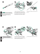
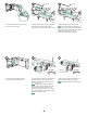
Disconnect all cables from the rear of the printer. NOTE There might be additional cables connected to the printer that are not shown below. Make sure that you disconnect all of the cables from the rear of the printer. To replace the transfer roller: CAUTION Never expose the print cartridge to bright direct light. Cover the print cartridge when it is removed from the printer to prevent the cartridge from being damaged. Open the top cover and remove the print cartridge.
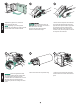
English English CAUTION Do not touch the replacement transfer roller with bare hands. Skin oils on the roller can cause print-quality problems. Put on the gloves and remove the replacement transfer roller from the protective bag. To replace the tray 1 pickup roller: If an optional envelope feeder is not installed, open tray 1 and remove the front accessory cover. Make sure that the black collar on the left side is oriented properly, with the open end down.
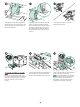
Release the roller by sliding apart the two latches located on each side at the top of the pickup roller (callout 1). Lift the roller out of the opening (callout 2). Place the new pickup roller onto the shaft (callout 1). Align the pin that is located on each side at the bottom of the roller with the slot in the bracket located on each side of the opening (callout 2). Slide the roller into the printer until the roller snaps into place (callout 3).
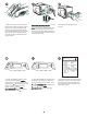
English English WARNING! Do not allow the front of the printer to extend beyond the edge of the table. The printer can become unbalanced and fall, causing damage or injury. Move the front of the printer to the edge of the table top for better access to the feed roller that is located inside the printer. Insert tray 2. NOTE Depending upon which optional accessories are installed, you might not need all of the feed rollers included in this kit.
On the inside of the door, open the small cover next to the feed roller. Push the blue latch that is on the side of the feed roller away from the roller shaft to unlock the roller. Slide the roller off the shaft. Slide the new feed roller onto the shaft. NOTE It is important that this roller locks into place. If it does not, make sure that the roller is properly oriented and that the round, black spacer next to the roller is properly positioned around the pin in the shaft.
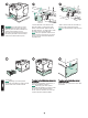
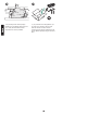
English English Replace the paper in the 1,500-sheet feeder and close the door. NOTE Depending upon which optional accessories are installed, you might not need all of the feed rollers included in this kit. WARNING! The fuser might be hot. Make sure that the printer has been turned off for 30 minutes before removing the fuser. Locate the blue fuser release levers on each side of the fuser. Pinch the blue levers upward and pull the fuser straight out of the printer.
Install the rear output bin. Insert the right hinge pin in the hole in the chassis. Push the left-side of the output bin toward the rightside of the printer. Slide left hinge into the printer until the left hinge pin is inserted into the hole in the chassis. Pull gently on the output bin to make sure that the hinge pins are fully inserted. After installing the maintenance kit: Connect the cables to the rear of the printer.
English if any kit components were improperly installed or not completely seated, jams can occur. Verify that the maintenance kit components are correctly installed. If you purchased an exchangeable kit, you can return your old fuser to HP for credit. Pack the old fuser and other used kit components in the packing material from the new kit. Mail the package using the enclosed label.
Débranchez tous les câbles à l'arrière de l'imprimante. Remarque Il se peut que d'autres câbles connectés à l'imprimante ne figurent pas sur l'illustration ci-dessous. Assurez-vous de déconnecter tous les câbles à l'arrière de l'imprimante. Pour remplacer le rouleau de transfert : ATTENTION N'exposez jamais la cartouche d'impression à une lumière directe intense. Lorsque vous ôtez la cartouche d'impression de l'imprimante, couvrez-la afin de ne pas l'endommager.
Français Français ATTENTION Ne touchez pas le rouleau de transfert de remplacement avec les mains nues. La présence de traces de doigts sur le rouleau peut nuire à la qualité d'impression. Mettez les gants et retirez le rouleau de transfert de remplacement du sachet de protection. Pour remplacer le rouleau d'entraînement du bac 1 : Si aucun bac à enveloppes optionnel n'est installé, ouvrez le bac 1 et retirez le couvercle frontal pour accessoires.
Dégagez le rouleau en faisant glisser les deux loquets situés en haut du rouleau d'entraînement, de chaque côté (référence 1). Soulevez le rouleau par l'ouverture (référence 2). Placez le nouveau rouleau d'entraînement sur l'axe (référence 1). Alignez la broche située en bas du rouleau, de chaque côté, sur la fente du support situé de part et d'autre de l'ouverture (référence 2). Faites glisser le rouleau dans l'imprimante. Il doit s'enclencher (référence 3).
Français Français AVERTISSEMENT L'avant de l'imprimante ne doit pas dépasser du bord de la table. L'imprimante risquerait de tomber, et d'occasionner des dommages ou des blessures. Placez l'avant de l'imprimante au bord de la table pour accéder plus facilement au rouleau d'alimentation. Insérez le bac 2. Remarque Le nombre de rouleaux d'alimentation nécessaires à l'opération de maintenance dépendra des accessoires optionnels installés.
Sur la paroi interne de cette porte, ouvrez le petit couvercle à côté du rouleau d'alimentation. Pour déverrouiller le rouleau d'alimentation, poussez sur le loquet bleu situé sur le côté du rouleau, dans la direction opposée à l'axe du rouleau. Faites glisser le rouleau hors de l'axe. Placez le nouveau rouleau d'alimentation sur l'axe. Remarque Enclenchez bien le rouleau. Si vous n'y parvenez pas, vérifiez l'orientation du rouleau.
Français Français Replacez le papier dans le chargeur de 1 500 feuilles et fermez la porte. Remarque Le nombre de rouleaux d'alimentation nécessaires à l'opération de maintenance dépendra des accessoires optionnels installés. AVERTISSEMENT L'unité de fusion peut être chaude. Mettez l'imprimante hors tension 30 minutes avant de désinstaller l'unité. Identifiez les leviers bleus de verrouillage de l'unité de fusion situés sur chaque côté de celle-ci.
Installez le bac de sortie arrière. Insérez la broche de charnière droite dans le trou du châssis. Poussez le côté gauche du bac de sortie vers le côté droit de l'imprimante. Glissez la charnière gauche dans l'imprimante jusqu'à ce que la broche de la charnière gauche soit insérée dans le trou du châssis. Tirez doucement sur le bac de sortie pour vérifier que les broches de charnière sont complètement insérées. Après avoir installé le kit de maintenance : Branchez les câbles à l'arrière de l'imprimante.
Français Des bourrages risquent de se produire si des composants du kit ont été mal installés ou ne sont pas bien en place. Vérifiez que les composants du kit de maintenance sont correctement installés. Si vous avez acheté un kit échangeable, vous pouvez renvoyer l'ancienne unité de fusion à HP pour obtenir un avoir. Rangez l'ancienne unité de fusion et les autres composants utilisés du kit dans l'emballage du nouveau kit. Expédiez le colis en vous servant de l'étiquette jointe.
Ziehen Sie alle Kabel an der Rückseite des Druckers ab. Hinweis An den Drucker sind möglicherweise weitere Kabel angeschlossen, die nachfolgend nicht abgebildet sind. Stellen Sie sicher, dass Sie alle Kabel an der Rückseite des Druckers abziehen. So tauschen Sie die Transferwalze aus: VORSICHT Setzen Sie die Tonerpatrone keinesfalls hellem, direktem Licht aus. Decken Sie die Tonerpatrone zum Schutz vor einer Beschädigung ab, nachdem sie aus dem Drucker entfernt wurde.
Deutsch Deutsch VORSICHT Berühren Sie die Ersatztransferwalze nicht ohne Handschuhe. Hautfette auf der Walze können die Druckqualität beeinträchtigen. Ziehen Sie die Handschuhe an, und nehmen Sie die Ersatztransferwalze aus der Schutzhülle. Achten Sie darauf, dass die schwarze Klemme auf der linken Seite ordnungsgemäß ausgerichtet ist. Die geöffnete Seite muss nach unten weisen. Setzen Sie die neue Transferwalze ein, indem Sie die rechte Seite einschieben (1).
Lösen Sie die Walze, indem Sie die beiden Verriegelungen außen an der Oberseite der Einzugswalze auseinander ziehen (1). Heben Sie die Walze an der Öffnung heraus (2). Setzen Sie die neue Einzugswalze an der Welle ein (1). Richten Sie die Stifte an der Unterseite der Walze an den Aussparungen der Halterungen außen an der Öffnung aus (2). Schieben Sie die Walze in den Drucker, bis sie hörbar einrastet (3). Installieren Sie die vordere Zubehörabdeckung oder die optionale Umschlagzufuhr.
Deutsch Deutsch ACHTUNG! Die Vorderseite des Druckers sollte nicht über die Tischkante hinausragen. Der Drucker könnte fallen und Schäden oder Verletzungen verursachen. Schieben Sie die Vorderseite des Druckers zur Tischkante, damit Sie besser auf die Zufuhrwalze im Drucker zugreifen können. Setzen Sie Fach 2 ein. Hinweis Je nachdem, welches optionale Zubehör installiert ist, benötigen Sie möglicherweise nicht alle der in diesem Kit enthaltenen Zufuhrwalzen.
Öffnen Sie an der Klappeninnenseite die kleine Abdeckung neben der Zufuhrwalze. Ziehen Sie die blaue Verriegelung seitlich an der Zufuhrwalze von der Walzenwelle weg, um die Walze zu entriegeln. Schieben Sie die Walze von der Welle. Schieben Sie die neue Zufuhrwalze auf die Welle. Hinweis Achten Sie darauf, dass die Walze einrastet. Vergewissern Sie sich andernfalls, dass sie richtig ausgerichtet ist und der runde schwarze Abstandhalter neben der Walze den Stift der Welle umschließt.
Deutsch Deutsch Legen Sie das Papier wieder in das 1500Blatt-Zufuhrfach ein, und schließen Sie die Klappe. Hinweis Je nachdem, welches optionale Zubehör installiert ist, benötigen Sie möglicherweise nicht alle der in diesem Kit enthaltenen Zufuhrwalzen. ACHTUNG! Die Fixiereinheit ist unter Umständen heiß. Schalten Sie den Drucker aus, und nehmen Sie die Fixiereinheit erst 30 Minuten später heraus. Die blauen Verriegelungshebel befinden sich auf beiden Seiten der Fixiereinheit.
Setzen Sie das hintere Ausgabefach ein. Setzen Sie das rechte Scharnier in das Loch im Druckergehäuse ein. Drücken Sie die linke Seite des Ausgabefachs zur rechten Seite des Druckers. Schieben Sie das linke Scharnier in den Drucker, so daß der linke Scharnierstift in das Loch im Druckergehäuse gleitet. Stellen Sie sicher, dass die Scharnierstifte vollständig eingeführt sind, indem Sie vorsichtig am Ausgabefach ziehen.
Deutsch Bei nicht ordnungsgemäß oder nicht vollständig eingesetzten Komponenten des Wartungskits treten u.U. Papierstaus auf. Vergewissern Sie sich, dass die Komponenten des Wartungskits korrekt eingesetzt wurden. Wenn Sie ein Wartungskit zur Rückgabe erworben haben, können Sie die gebrauchte Fixiereinheit gegen eine Gutschrift zu Hewlett-Packard zurücksenden. Verpacken Sie die gebrauchte Fixiereinheit und verbrauchte Kit-Komponenten mit dem Verpackungsmaterial des neuen Wartungskits.
Scollegare tutti i cavi dal retro della stampante. Nota Potrebbero essere presenti altri cavi collegati alla stampante, non visualizzati nell'illustrazione riportata sotto. Controllare di aver scollegato tutti i cavi presenti sul retro della stampante. Per sostituire il rullo di trasferimento: ATTENZIONE Non esporre mai la cartuccia di stampa alla luce diretta. Una volta estratta dalla stampante, coprire la cartuccia di stampa per evitare che venga danneggiata.
Italiano Italiano ATTENZIONE Non toccare il rullo di trasferimento sostitutivo con le mani non protette da guanti. L'untuosità della pelle può causare problemi di qualità di stampa. Estrarre il rullo di trasferimento sostitutivo dall'involucro protettivo indossando i guanti. Per sostituire il rullo di estrazione del vassoio 1: Qualora l'alimentatore buste opzionale non fosse installato, aprire il vassoio 1 e rimuovere il coperchio dell'accessorio frontale.
Rilasciare il rullo facendo scorrere i due saliscendi che si trovano su ciascun lato nella parte superiore del rullo di estrazione (richiamo 1). Estrarre il rullo dall'apertura (richiamo 2). Posizionare il nuovo rullo di estrazione nell'asta (richiamo 1). Allineare il piedino che si trova su ciascun lato nella parte inferiore del rullo con l'alloggiamento nella staffa presente su ogni lato dell'apertura (richiamo 2). Far scorrere il rullo nella stampante fino a quando non scatta in posizione (richiamo 3).
Italiano Italiano AVVERTENZA Non fare sporgere la stampante oltre il bordo del piano di appoggio. La stampante potrebbe sbilanciarsi e cadere, provocando lesioni personali o subendo dei danni. Spostare la parte anteriore della stampante verso il bordo del piano di appoggio per accedere più facilmente al rullo di alimentazione nella stampante. Inserire il vassoio 2. Nota A seconda del tipo di accessori opzionali installati, potrebbero non essere necessari tutti i rulli di alimentazione inclusi nel kit.
Nella parte interna dello sportello, aprire lo sportello più piccolo accanto al rullo di alimentazione. Premere il saliscendi blu situato su un lato del rullo di alimentazione scostandolo dall'asta del rullo per sbloccare quest'ultimo. Fare scorrere il rullo fuori dall'asta. Fare scorrere il nuovo rullo di alimentazione nell'asta. Nota È importante che questo rullo sia ben inserito e bloccato.
Italiano Italiano Riporre la carta nell'alimentatore da 1.500 fogli e chiudere lo sportello. Nota A seconda del tipo di accessori opzionali installati, potrebbero non essere necessari tutti i rulli di alimentazione inclusi nel kit. AVVERTENZA L'unità di fusione potrebbe essere molto calda. Assicurarsi che la stampante sia stata spenta per 30 minuti prima di rimuovere l'unità di fusione. Individuare le leve blu di rilascio dell'unità di fusione su ciascun lato della stessa.
Installare lo scomparto di output posteriore. Inserire il piedino del cardine destro nel foro dello chassis. Premere il lato sinistro dello scomparto di output verso il lato destro della stampante. Fare scorrere il cardine sinistro nella stampante fino al completo inserimento del piedino del cardine sinistro nel foro dello chassis. Tirare delicatamente lo scomparto di output per accertarsi che i piedini siano inseriti completamente.
Italiano se i componenti del kit non sono stati installati o collocati correttamente, possono verificarsi degli inceppamenti della carta. Controllare che i componenti del kit di manutenzione siano installati correttamente. Se si è acquistato un kit che si può cambiare, è possibile restituire la vecchia unità di fusione alla HP. Imballare la vecchia unità di fusione e gli altri componenti del kit usati con il materiale di imballaggio del nuovo kit.
Gire la impresora de manera que la cubierta posterior quede ante usted. En caso de que la unidad opcional de impresión dúplex esté instalada, levántela y tire de ella para sacarla. Desconecte todos los cables de la parte posterior de la impresora. Nota Es posible que haya otros cables conectados a la impresora que no se muestren a continuación. Asegúrese de desconectar todos los cables de la parte posterior de la impresora.
Español Español PRECAUCIÓN No toque el nuevo rodillo de transferencia sin utilizar los guantes. Si quedara grasa de la piel sobre el rodillo podría verse afectada la calidad de la impresión. Póngase los guantes y saque el rodillo de transferencia nuevo de la bolsa protectora. Asegúrese de que la abrazadera negra del lado izquierdo queda debidamente orientada, con el extremo abierto hacia abajo. Instale el nuevo rodillo de transferencia deslizando el lado derecho hasta que encaje en su sitio (leyenda 1).
Suelte el rodillo separando las dos palancas azules situadas a cada lado de la parte superior del mismo (leyenda 1). Levante el rodillo y sáquelo por la abertura (leyenda 2). Coloque el nuevo rodillo de recogida sobre el eje (leyenda 1). Alinee los pasadores situados a ambos lados del rodillo (en su parte inferior) con las ranuras de los soportes situados a cada lado de la abertura. Deslice el rodillo hasta que encaje en la impresora con un clic (leyenda 3).
Español Español ADVERTENCIA No deje que la parte frontal de la impresora sobresalga del borde de la mesa. La impresora puede desequilibrarse y caer, lo que podría causar daños personales o materiales. Mueva la parte frontal de la impresora hasta el borde de la mesa para tener un acceso más cómodo al rodillo de alimentación, que está situado en el interior de la impresora. Inserte la bandeja 2.
En el interior de la puerta, abra la cubierta pequeña junto al rodillo de alimentación. Para abrir el rodillo, presione la palanca azul situada en la parte lateral del rodillo de alimentación alejándola del eje del rodillo. Extraiga el rodillo del eje. Coloque el rodillo de alimentación nuevo en el eje. Nota Es importante que el rodillo quede bien encajado en su sitio.
Español Español Coloque el papel en el alimentador de 1500 hojas y cierre la puerta. Nota Según los accesorios opcionales que se instalen, quizá no sean necesarios todos los rodillos de alimentación contenidos en el kit. ADVERTENCIA El fusor puede estar caliente. Asegúrese de que la impresora ha estado apagada durante al menos 30 minutos antes de retirar el fusor. Busque las palancas azules de apertura del fusor a cada lado de éste.
Instale la bandeja de salida posterior. Inserte la clavija de la bisagra en el agujero del chasis. Empuje el lado izquierdo de la bandeja de salida hacia el lado derecho de la impresora. Deslice la bisagra izquierda en la impresora hasta que la clavija de la bisagra izquierda se inserte en el agujero del chasis. Tire suavemente de la bandeja de salida para asegurarse de que las clavijas de la bisagra queden perfectamente encajadas.
Español Pueden producirse atascos si alguno de los componentes del kit no se instala correctamente o no queda fijo en su posición. Compruebe si los componentes del kit de mantenimiento se han instalado correctamente. Si adquirió un kit intercambiable, podrá devolver su fusor usado a HP a cambio de vales de compra. Embale el fusor y cualquier otro componente usado del kit con el material de embalaje del kit nuevo. Envíe el paquete por correo utilizando la etiqueta adjunta.
주의 퓨저를 교체하는 경우, 프린터를 끄고 30 분 동안 퓨저를 냉각시켜야 합니다. 프린터의 전원을 끄십시오. 이동 롤러 교체 방법: 주의 토너 카트리지를 직사 광선에 노출시키 지 마십시오. 토너 카트리지를 프린터에서 꺼 낸 경우 손상되지 않도록 덮어두십시오. 상단 덮개를 열고 토너 카트리지를 꺼내십시 오. 이동 롤러는 토너 카트리지가 있던 공간 아 래에 있습니다. 43 프린터 뒤 덮개를 볼 수 있도록 돌리십시오. 선택사양인 듀플렉서를 이미 설치한 경우, 들 어올려 꺼내십시오. 주의 이동 롤러를 꺼낼 때 롤러의 왼쪽 끝을 들 어올리지 마십시오. 플라스틱 이동 롤러 도구를 사용하여(1) 금속 으로 된 축의 왼쪽 끝을 살짝 들어올리십시오 (2). 이동 롤러를 왼쪽으로 밀어 꺼내십시오 (3). 한국어 프린터에 연결된 케이블을 모두 분리하십시 오. 주 아래에 표시되지 않은 추가적인 케이블이 프린터에 연결되어 있을 수 있습니다. 프린터 후면에서 모든 케이블을 분리하십시오.
한국어 한국어 주의 롤러에 손때가 묻으면 인쇄 상태가 나빠 질 수 있으므로 맨손으로 만지지 마십시오. 장갑을 낀 다음 보호 봉투에서 이동 롤러를 꺼 내십시오. 용지함 1 픽업 롤러 교체 방법: 봉투 공급장치 (선택사양)를 설치하지 않은 경우에는 용지함 1을 열고 전면 부속품 덮개를 떼어내십시오. 왼쪽에 있는 검은색 칼라 끝이 아래쪽을 향하 고 있는지 확인하십시오. 이동 롤러의 오른쪽 부분을 끼운 다음(1), 기어가 있는 왼쪽을 제자 리에 끼우십시오(2). 선택사양인 봉투 공급장치를 이미 설치한 경 우, 분리 버튼을 누르고(1) 봉투 공급장치(2) 를 꺼내십시오. 44 토너 카트리지를 넣고 상단 덮개를 닫으십시 오. 픽업 롤러는 용지함 1의 중앙에 있습니다.
픽업 롤러 상단의 양쪽에 있는 걸쇠를 풀어 롤러를 분리하십시오(1). 롤러를 입구에서 들 어올리십시오(2). 새 픽업 롤러를 축에 끼우십시오(1). 양 옆에 있는 브래킷 슬롯과 롤러 하단 양 옆에 있는 핀 을 맞추십시오(2). 롤러가 제자리에 고정될 때 까지 롤러를 밀어 넣으십시오(3). 전면 부속품 덮개 또는 봉투 공급장치(선택사 양)을 끼우십시오. 용지함 2 급지 및 분리 롤러 교체 방법: 용지 함 2의 용지를 꺼내십시오. 용지함을 잡아 당 긴 다음 용지함의 전면을 약간 들어올려 프린 터에서 꺼내십시오. 용지함 덮개는 급지 롤러 옆에 있습니다. 덮개를 위로 돌려 여십시오. 급지 롤러의 왼쪽에 있는 파란색 걸쇠를 롤 러 축 밖으로 밀어 롤러의 잠금을 푸십시오. 롤 러를 밀어 축에서 떼어내십시오. 새 급지 롤러를 축에 밀어넣으십시오. 아래쪽 로 돌려 덮개를 닫으십시오. 주 롤러는 제대로 고정되어 있어야 합니다.
한국어 한국어 경고! 프린터 앞이 테이블 가장자리 밖으로 나 오지 않게 하십시오. 프린터가 지나치게 한 쪽 으로 기울면 떨어져서 프린터가 손상되거나 부상을 입을 수 있습니다. 급지 롤러 작업을 쉽게 할 수 있도록 프린터 앞 을 테이블 상단 가장자리에 붙이십시오. 용지함 2을 끼우십시오. 주 설치된 선택사양 부속품에 따라 이 키트에 들어 있는 급지 롤러가 모두 필요하지 않을 수 있습니다. 급지 롤러(1)의 왼쪽에 있는 파란색 걸쇠를 롤러 축 밖으로 밀어 롤러의 잠금을 푸십시오. 롤러를 밀어 축에서 떼어내십시오(2). 걸쇠의 잠금을 풀려면 롤러를 돌리십시오. 주 용지함 2 분리 롤러는 프린터 전면에 가장 가까이 있는 롤러입니다. 분리 롤러의 뒤에 있 는 용지함 2 픽업 롤러를 분리하지 마십시오. 새 급지 롤러를 밀어 축에 끼우고 제대로 고 정될 때까지 돌리십시오. 주 롤러는 제자리에 고정되어 있어야 합니다.
도어 안쪽에서, 급지 롤러 옆에 있는 작은 덮 개를 여십시오. 급지 롤러의 옆에 있는 파란색 걸쇠를 롤러 축 밖으로 밀어 롤러의 잠금을 푸십시오. 롤러 를 밀어 축에서 떼어내십시오. 새 급지 롤러를 밀어 축에 끼우십시오. 주 롤러는 제대로 고정되어 있어야 합니다. 제 대로 고정되지 않은 경우에는 롤러 방향이 올 바른지, 롤러 옆에 있는 둥근 검은색 스페이서 가 축의 핀 주위에 제대로 설치되어 있는지 확 인하십시오. 두 번째 급지 롤러는 1,500매 공급장치 안의 상단 중앙에 있습니다. 롤러(1)의 왼쪽에 있는 파란색 걸쇠를 롤러 축 밖으로 밀어 롤러의 잠금을 푸십시오. 롤러 를 밀어 축에서 떼어내십시오(2). 주 걸쇠의 잠금을 풀려면 롤러를 돌리십시오. 1,500매 공급장치 분리 롤러는 프린터 전면에 가장 가까이 있는 롤러입니다. 분리 롤러의 뒤 에 있는 1,500매 공급장치 픽업 롤러를 분리하 지 마십시오. 주 새 급지 롤러를 밀어 축에 끼우고 제대로 고 정될 때까지 돌리십시오.
한국어 한국어 1,500매 공급장치의 용지를 교체하고 도어 을 닫으십시오. 주 설치된 선택사양 부속품에 따라 이 키트에 들어 있는 급지 롤러가 모두 필요하지 않을 수 있습니다. 경고! 퓨저가 뜨거울 수도 있으므로, 프린터를 끄고 30분 동안 퓨저의 열을 식힌 후에 퓨저 를 꺼내십시오. 파란색 퓨저 분리 레버는 퓨저의 양쪽에 있습 니다. 파란색 레버를 위로 잡고 퓨저를 당겨 꺼 내십시오. 퓨저 교체 방법: 주의 퓨저를 교체하는 경우, 프린터를 끄고 30 분 동안 퓨저를 냉각시켜야 합니다. 후면 출력 용지함을 열고 확장판을 끝까지 당 기십시오. 보호 봉투에서 퓨저를 꺼내십시오. 48 경첩이 프린터 본체의 장착 구멍에서 나올 때 까지 프린터의 오른쪽을 향해 왼쪽 경첩을 밀 어 후면 출력 용지함과 확장판을 꺼내십시오. 출력 용지함의 왼쪽과 확장판을 돌려 프린터 에서 꺼내십시오. 퓨저 양쪽의 파란색 레버가 딱 소리가 나면 서 고정될 때까지 퓨저를 밀어 넣으십시오.
후면 출력 용지함을 다시 끼우십시오. 본체 의 구멍에 오른쪽 경첩 핀을 끼우십시오. 출력 용지함의 왼쪽을 프린터의 오른쪽을 향해 밀 어넣으십시오. 왼쪽 경첩 핀이 본체의 구멍에 끼워질 때까지 왼쪽 경첩을 프린터로 밀어넣 으십시오. 경첩 핀이 완전히 끼워지도록 출력 용지함을 살짝 당기십시오. 유지보수 키트를 설치한 후에 해야 할 작업: 케이블을 프린터에 다시 연결하십시오. 주 이 그림에 표시되지 않은 추가적인 케이블 이 프린터에 연결되어 있을 수 있습니다. 이전 에 프린터에 연결되었던 모든 케이블을 연결 하십시오. 선택사양인 듀플렉서를 이미 분리한 경우, 다 시 끼우십시오. hp LaserJet 4250/4350 series 1 설치 마무리 방법: 프린터의 전원을 끄십시 오. 제어판 디스플레이에 메시지 XXXMB가 표 시되면, 세 개의 제어판 표시등이 켜질 때까지 몇 초 동안 을 누르십시오. NEW MAINTENANCE KIT 메시지가 나타날 때까지 를 누른 후 를 누르십시오.
한국어 키트 부품이 잘못 설치되거나 완전히 고정되 지 않으면 용지가 걸릴 수 있습니다. 유지보수 키트 부품이 올바로 설치되었는지 확인하십시 오. 교환용 키트를 구입한 경우, 기존 퓨저를 hp 에 반환해야 포인트를 받을 수 있습니다. 퓨저 를 비롯한 사용하던 기타 부품은 새 키트의 포 장재로 싸고 동봉한 레이블을 부착하여 우편 으로 보내십시오.
拔下印表機背面所有的電纜。 注意 印表機背面可能還連接其他下圖未顯示的 電纜。請確定您已經拔下印表機背面所有的電 纜。 更換傳送滾筒: 小心 切勿將碳粉匣直接曝露在強光下。碳粉匣 從印表機中取出後,請妥善遮蓋,以避免損害 碳粉匣。 打開頂蓋並取出碳粉匣。然後在已取出碳粉匣 的區域下方找出傳送滾筒。 51 轉動印表機使其背面護蓋朝向自己。如果已 安裝選購的雙面列印裝置,請提起並拉出該雙 面列印裝置以將其卸下。 小心 當取出傳送滾筒時,請勿將傳送滾筒的左 側過高抬起。 使用塑膠傳送滾筒工具 (1),將金屬軸的左側 稍微向上抬起 (2)。然後將傳送滾筒滑至左側 並將其取出 (3)。 繁體中文 安裝維護套件前: 小心 更換熱凝器前,印表機的電源必須關閉 30 分鐘,讓熱凝器冷卻。 關閉印表機電源。 繁體中文 本包裹有一個維護套件 (Q5421A 110 V 套件 或 Q5422A 220 V 套件),內含一個熱凝器、 一個傳送滾筒、一個塑膠傳送滾筒工具、一個 拾取滾筒、八個送紙滾筒和一對拋棄式手套。 本套件的成本並不包含在原印表機保固或最大 延長保固之內。 注意 視選購附件的不同,您可能不需要此套件
繁體中文 繁體中文 小心 請勿徒手更換傳送滾筒。如果捲筒沾上皮 膚的油脂,則會導致列印品質問題。 戴上手套,將要更換的傳送滾筒從保護套中取 出。 更換 1 號紙匣的拾取滾筒 如果未安裝選購的 信封進紙器,請打開 1 號紙匣,然後卸下前附 件蓋。 請確保左側的黑色軸環已正確定位,開口端 向下。安裝新的傳送滾筒:將右側滑入定位 (1)。然後將左側(帶有齒輪)卡入定位 (2)。 安裝碳粉匣,然後合上頂蓋。 如果已安裝選購的信封進紙器,請按下信封 進紙器釋放按鈕 (1) 並向外拉信封進紙器 (2), 以將其卸下。 找出 1 號紙匣中央的拾取滾筒。 52
將位於拾取滾筒頂端兩側的閘鎖推開,鬆開 滾筒 (1)。將滾筒從開口處抬起 (2)。 將新的拾取滾筒放在主軸上 (1)。將位於滾筒 底端兩側的卡榫,與開口兩側托架中的插槽對 齊 (2)。將滾筒滑入印表機,直到滾筒卡入定 位 (3)。 更換 2 號紙匣的送紙和分離滾筒: 將 2 號紙 匣中的任何耗材取出。拉出紙匣,稍微抬起紙 匣的前端,將它從印表機中取出。接著找出送 紙滾筒旁邊的紙匣上的護蓋。然後向上轉動護 蓋以將其打開。 將送紙滾筒左側的藍色閘鎖推離滾筒主軸, 以解開滾筒。將滾筒從主軸中滑出。 53 插入前附件蓋或選購的信封進紙器。 將新的送紙滾筒滑在主軸上。將它向下旋轉 以關閉頂蓋。 注意 請務必將此滾筒鎖定到位。否則,請確保 滾筒已正確定位,且滾筒旁邊的黑色圓形墊塊 已正確定位在主軸中的卡榫周圍。
繁體中文 繁體中文 警告! 請勿讓印表機正面超出桌緣。否則,印 表機可能會不穩甚至跌落,導致損壞或人身傷 害。 將印表機正面移至桌緣,以更方便地裝卸印表 機內的送紙滾筒。 插入 2 號紙匣。 注意 視選購附件的不同,您可能不需要此套件 提供的所有送紙滾筒。 將 送紙 滾筒 左側的 藍 色閘 鎖推 離滾 筒主 軸 (1),以解開滾筒。然後將滾筒從主軸中滑出 (2)。您可能需要轉動滾筒才能解開閘鎖。 注意 2 號紙匣分離滾筒是最接近印表機正面的 滾筒。切勿取出位於分離滾筒背面的 2 號紙匣 拾取滾筒。 將新的送紙滾筒滑在主軸上,然後轉動滾筒 直至其鎖定到位。 注意 請務必將滾筒鎖定到位。 更換選購的可容納 500 張紙的進紙器中的送紙 滾筒: 若要在選購的 500 張紙進紙器中安裝 送紙滾筒,請重複 2 號紙匣送紙滾筒安裝程 序。 注意 視選購附件的不同,您可能不需要此套件 提供的所有送紙滾筒。 HP LaserJet 4250/4350 最多可安裝 3 個選購 的 500 張紙進紙器。 更換選購的可容納 500 張紙的進紙器中的送紙 滾筒: 向下按壓釋放柄,然後打開可容納 1500 張紙的進紙器擋
在擋門內部,打開送紙滾筒旁邊的小護蓋。 將送紙滾筒側邊的藍色閘鎖推離滾筒主軸, 以解開滾筒。將滾筒從主軸中滑出。 將新的送紙滾筒滑在主軸上。 注意 請務必將此滾筒鎖定到位。否則,請確保 滾筒已正確定位,且滾筒旁邊的黑色圓形墊塊 已正確定位在主軸中的卡榫周圍。 找出第二個可容納 1,500 張紙進紙器內中上 部的送紙滾筒。 將滾筒左側的藍色閘鎖推離滾筒主軸 (1),以 解開滾筒。然後將滾筒從主軸中滑出 (2)。 注意 您可能需要轉動滾筒才能解開閘鎖。 1,500 張紙進紙器分離滾筒是最接近進紙器正 面的滾筒。切勿取出位於分離滾筒背後的 1,500 張紙進紙器拾取滾筒。 注意 將新的送紙滾筒滑在主軸上,然後轉動滾筒 直至其鎖定到位。 注意 請務必將滾筒鎖定到位。 55
繁體中文 繁體中文 將紙張放回 1,500 張紙進紙器,並關上門。 注意 視選購附件的不同,您可能不需要此套件 提供的所有送紙滾筒。 警告! 熱凝器可能很燙。請確保已關閉印表機 電源 30 分鐘,再取出熱凝器。 找到熱凝器兩側的藍色熱凝器釋放柄。向上推 藍色手柄並將熱凝器平直地拉出印表機。 更換熱凝器: 小心 更換熱凝器前,印表機的電源必須關閉 30 分鐘,讓熱凝器冷卻。 打開後出紙槽並拉出延伸板,直至其停止。 將熱凝器從保護套中取出。 56 將左側的鉸接栓向印表機的右側推,直到鉸 接栓越過印表機底座的小孔為止,便可移除後 出紙槽及延伸板。將出紙槽和延伸板的左側轉 離印表機,取出出紙槽和延伸板。 將新的熱凝器平穩地推入印表機,直至兩側 的藍色手柄卡入定位。
安裝後出紙槽。將右鉸接栓插入底座的洞。 將出紙槽的左側向印表機右側推。將左鉸接栓 滑入印表機,直到左鉸接栓插入底座的洞中。 輕輕地推後出紙槽以確定鉸接栓完全插入。 安裝維護套件後: 將電纜連接至印表機背 面。 注意 印表機可能會連接其他本圖中未顯示的電 纜。請確定您連接了先前與印表機連接的所有 電纜。 安裝選購的雙面列印裝置 (如果它已卸下)。 hp LaserJet 4250/4350 series 1 完成安裝:開啟印表機電源。當控制面板顯 要確認安裝是否完成,請從控制面板列印組 示幕出現 XXXMB 訊息時,按住 數秒,直 到三個控制面板燈全部開啟,並持續亮著。按 態頁。按下 下 直 至 顯 示 幕 上 出 現 NEW MAINTENANCE KIT(新的維護套件)訊息, 下 。 按 下 以 選 擇 PRINT CONFIGURATION(列印組態),然後按下 然後按下 。 以開啟印表機功能表。按下 以選擇 INFORMATION(資訊),然後按 。 57 檢查「Pages since last maintenance」(自 上次維護的頁數)之數字是否重設為零。如果
繁體中文 如果套件元件未正確安裝或未完全就位,可 能會發生卡紙。確認維護套件的零件皆正確安 裝。 如果您購買了可替換的套件,您可以將舊的 熱凝器退回給 HP 以獲得退款。用新套件的包 裝材料將舊的熱凝器與其他用過的套件元件包 裝好。然後使用隨附的標籤郵寄包裹。 58
© 2005 Hewlett-Packard Development Company, L.P. www.hp.