RC3000 MOBILE ANTENNA CONTROLLER USER’S MANUAL Contents subject to change 1 December 2005 RESEARCH CONCEPTS INC. 5420 Martindale Road Shawnee, Kansas 66218-9680 USA VOICE: (913) 422-0210 FAX: (913) 422-0211 www.researchconcepts.com support@researchconcepts.
REVISION HISTORY DATE 8 March 1999 13 April 1999 1 June 1999 13 March 2000 15 November 2002 10 January 2003 3 January 2005 1 December 2005 MODIFICATION Preliminary document Initial Release Update Software Update Chapter 2 Update Appendix E Update Manual Format Update Software Update SOFTWARE VERSION 1.00 1.04 1.07 1.16 1.37 1.38 1.46 1.
WARRANTY INFORMATION Research Concepts, Inc.(RCI) warrants to the original purchaser, this product shall be free from defects in material and workmanship for one year, unless expressed otherwise, from the date of the original purchase. During the warranty period, RCI will provide, free of charge, both parts and labor necessary to correct such defects.
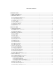
TABLE OF CONTENTS 1.0 INTRODUCTION.................................................................................................................................................1 1.1 MANUAL ORGANIZATION .....................................................................................................................................1 1.2 RC3000 FEATURES ..............................................................................................................................................3 1.
3.0 DETAILED OPERATION ................................................................................................................................ 63 3.1 OPERATION OVERVIEW ...................................................................................................................................... 63 3.1.1 Modes......................................................................................................................................................... 63 3.1.2 Keypad Usage .........
3.3.2.5 Limits Maintenance ............................................................................................................................................. 123 3.3.2.6 GPS Serial Port Diagnostics ................................................................................................................................ 124 3.3.2.7 Fluxgate Serial Port Diagnostics.......................................................................................................................... 124 3.
RC3000 Antenna Controller Chapter 1 Introduction 1.0 INTRODUCTION The RC3000 antenna controller is designed for use with elevation over azimuth antennas on mobile satellite uplink vehicles. The RC3000 assists both the technically-oriented and the non-technical operator of a mobile satellite antenna system by automating the process of locating and locking on to a particular satellite. This process can be time-consuming due to several factors.
RC3000 Antenna Controller Chapter 1 Introduction MANUAL CONVENTIONS Throughout the manual, representations of screens the user will see will be shown in the boxed format that follows: AZIM: 0.0 STOW SS1: 50 MANUAL ELEV: -67.5 STOW SAT:TELSTAR 402 POL: 0.0 SPD:FAST CST <0-9>JOG ANTENNA MENU 14:25:47 The following table shows typical abbreviations used both on RC3000 screens and in the manual’s text.
RC3000 Antenna Controller Chapter 1 Introduction 1.2 RC3000 Features The RC3000 antenna controller is designed to automate the operation of mobile (both vehicle mounted and deployable) mounts.
RC3000 Antenna Controller Chapter 1 Introduction Software Configuration. The software configuration (SW:) field is presented in the form RC3K-ab-xyz: RC3K-(Mount Manufacturer/Model #)-(Nav Sensor Option)(Tracking Option)(Remote Option) Descriptions of the software configuration designations are provided in the following tables: Mount Manufacturer/Model # The software within the RC3000 is customized to account for specifics of individual mounts.
RC3000 Antenna Controller Chapter 1 Introduction 1.3 Theory of Operation The RC3000 performs its functions via digital and analog electronic equipment interfaced to the antenna’s motor drive and position feedback systems. This equipment is controlled through embedded software algorithms run by the RC3000’s microcontroller. This section provides an overview of the equipment, interfaces and major software functions. 1.3.
RC3000 Antenna Controller Chapter 1 Introduction - performs communications between the microcontroller and the three (GPS, compass, remote control) serial channels - performs analog to digital conversion of drive position and signal strength inputs - performs automatic antenna movement algorithms (locate, stow, recall, track, etc) FEATURE BOARD. The feature board contains circuitry to implement many of the optional features of the RC3000.
RC3000 Antenna Controller Chapter 1 Introduction 1.3.3 Operational Overview The RC3000 allows easy antenna operation via its menu based user interface. The screen displayed to the user is based on the current controller mode. Controller modes are divided into two major groups: operational and programming (see mode map in section 3.1.1). The operational modes provide for the normal operation of the antenna.
RC3000 Antenna Controller Chapter 1 Introduction Programming Group Functions The programming group modes provide for initial configuration of the controller and also provide screens to aid in maintenance and troubleshooting of the controller. Configuration mode screens allow the user to customize and calibrate the operation of the RC3000 for use with a particular mount. Note that most configuration items will be factory set for correct operation with a particular mount. REF_VOLT:2.50 OFF: 0.
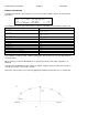
RC3000 Antenna Controller Chapter 1 Introduction 1.3.4 Antenna Pointing Solution The position (latitude and longitude) of the mount and the longitude of a selected satellite are required to calculate a pointing vector from the mount to the selected satellite. Given the mount’s latitude and longitude and the pointing vector to the satellite, the RC3000 calculates the elevation (with respect to local horizontal) required.
RC3000 Antenna Controller Chapter 1 Introduction The azimuth portion of the pointing vector is calculated with respect to local true North. The fluxgate compass is used to determine the heading of the centerline of azimuth travel and the required movement in the azimuth axis is calculated. In the above example a true heading of 135 degrees to the satellite has been calculated. Based on the mount’s latitude, longitude and date, a local magnetic variation (see 1.3.8) of 10 degrees is calculated.
RC3000 Antenna Controller Chapter 1 Introduction 1.3.5 Timekeeping There are several versions of time (system, sidereal, referenced and GPS) discussed within this manual. System time is maintained by the RC3000’s real time clock. The real-time clock is backed up by battery so that system time is available as soon as the RC3000 powers up. The system time is used to calculate sidereal time for maintaining track tables.
RC3000 Antenna Controller Chapter 1 Introduction In the azimuth axis, movement in one direction is disabled when clockwise and counterclockwise limit switches are activated. There is also typically a region in the center of azimuth travel indicating that the azimuth axis is in a position that will allow for moving the elevation axis down to the stow position. In the elevation axis, there are typically three limit switches. The UP switch prevents further movement up.
RC3000 Antenna Controller Chapter 1 Introduction The Fast/Slow Transition parameter defines how far away from a target position the RC3000 will switch from fast to slow motor speed. The Coast Range defines where the RC3000 will de-energize the motor drive to allow the mount’s inertia to coast into the target position. The Max Error parameter defines how close to the target position will be considered good enough.
RC3000 Antenna Controller Chapter 1 Introduction 1.3.8 Magnetic Variation In order to calculate satellite pointing solutions, the mount’s orientation with respect to true North must be known. The RC3000 uses the fluxgate compass to measure the local horizontal component of the earth’s magnetic field. The earth’s magnetic field is very irregular as shown in the following diagram from the National Geophysical Data Center. The magnetic field also changes slowly over time.
RC3000 Antenna Controller Chapter 1 Introduction 1.3.9 System Performance The performance achieved by the RC3000 in locating and tracking satellites is dependent on the mechanical tolerances of the mount, the correctness of the installation and the accuracy of the various sensors. The largest source of error for the system is due to errors in determining the truck's magnetic heading. Errors in heading primarily affect the accuracy of the antenna's calculated azimuth position.
RC3000 Antenna Controller Chapter 1 Introduction 1.4 Specifications RC3000A Physical Size Weight Input Power Fusing Temperature Humidity RC3000B 19.0 inches x 3.5 inches x 17.
RC3000 Antenna Controller Chapter 2 Installation 2.0 INSTALLATION Proper installation is important if the full capability and accuracy of the RC3000 is to be realized. The procedures that follow will insure the optimum level of performance from all sensors and the system in general. Installation will be more efficient if each step in the physical installation and calibration be performed in the order in which it appears in the following schedule.
RC3000 Antenna Controller Chapter 2 Installation 2.1 Equipment Mounting This section describes the physical mounting requirements for the RC3000 and optional sensor units. Wiring requirements are discussed in section 2.2. 2.1.1 RC3000 Antenna Controller NOTE: The RC3000 unit should not be installed in the rack until the final step of the Initial Configuration (section 2.3) because access to the interior of the unit may be necessary prior to that procedure.
RC3000 Antenna Controller Chapter 2 Installation 2.1.2 GPS Receiver The optional GPS receiver (RC3000GPS) should be mounted in a position (such as the truck’s roof) where it has an unobstructed view of the horizon and sky. It should be mounted outside of the reflector when in a stowed position, with the connector (on the underside) towards the cable’s entry point into the truck. Care should be taken in the routing of the cable to avoid any problems.
RC3000 Antenna Controller Chapter 2 Installation 2.1.3 Fluxgate Compass The optional fluxgate compass unit (RC3000FG) should be placed on the roof of the vehicle away from ferrous metals, electric motors, and any equipment that generates magnetic fields such as air conditioners, generators, and traveling wave tube (TWT) amplifiers. Experience has shown that the fluxgate performs best when mounted as high as possible on the vehicle. The fluxgate compass must be mounted in an upright position.
RC3000 Antenna Controller Chapter 2 Installation Stand on the roof of the vehicle with a standard magnetic compass. Slowly lower the compass to the proposed fluxgate mounting location on the vehicle without changing the orientation (or heading) of the compass body. If the needle of the compass swings as the compass is lowered to the mounting location, it is due to distortion of the earth's magnetic field by ferrous metals on the vehicle, or magnetic fields generated by the vehicle.
RC3000 Antenna Controller Chapter 2 Installation 2.1.4 Electronic Clinometer The electronic clinometer (also referred to as the inclinometer) should be positioned on the mount structure in an orientation that allows the inclinometer’s linear range of movement to rotate through the antenna’s RF boresight operational range. Determining the correct orientation of the inclinometer requires knowledge of the mount’s mechanical structure and the antenna’s RF offset.
RC3000 Antenna Controller Chapter 2 23 Installation
RC3000 Antenna Controller Chapter 2 Installation 2.2 Electrical Connections This section provides cabling requirements for interfacing to the RC3000. Note that cables should be made long enough to allow the unit to be open while still connected to the system. The following sections supply a schedule of connection requirements.
RC3000 Antenna Controller Chapter 2 Installation 2.2.1 Power Entry J6 is an IEC male power connector on the backpanel for supplying AC power to the RC3000. The RC3000 is shipped from the factory with a line cord appropriate for the line voltage selected. If the line cord received with the unit is not appropriate for the power available at the installation site, the installer should check the controller to ensure that the proper line voltage has been selected.
RC3000 Antenna Controller Chapter 2 Installation 2.2.2 Motor Drive J7 is an MS3102A22-20S (Female on backpanel) connector, which terminates three motor cables. The minimum wire size for these cables is 16AWG. The RC3000A is designed to drive 12 to 36 volt DC azimuth, elevation, and polarization motors. The absolute maximum allowed motor current is 12 Amps. The RC3000A employs a built-in, solid-state motor controller (model 25A8 from Advanced Motion Controls).
RC3000 Antenna Controller Chapter 2 Installation 2.2.3 Drive Sense J1 (DB-15 Female on backpanel) receives position sense from the azimuth and polarization potentiometers and the elevation inclinometer. Normally, it is not necessary to modify the sensors on the antenna. The antenna manufacturer should insure that the antenna is compatible with the RC3000. This information is provided for informational purposes only.
RC3000 Antenna Controller Chapter 2 Installation 2.2.4 Limit Switches J3 (DB-15 Female on backpanel) connects to the azimuth stow, elevation stow, elevation up and elevation down limit switches. The + side of each limit switch circuit supplies 12 VDC. This 12 VDC supply is protected by a resettable fuse rated at 250 mA. The azimuth stow switch must be closed when at the azimuth stow position.
RC3000 Antenna Controller Chapter 2 Installation 2.2.5 Signal Strength J2 (DB-15 Female on backpanel) connects to receivers, modems, etc., to provide signal strength indication for autopeaking and tracking. J2 also supports 4 bits of digital I/O and various bus voltages that allow for future expansion. The received signal strength from the system receiver must be between –15 VDC and +15 VDC. The signal may be of either positive or negative polarity (see section 2.4.3 - signal strength adjustment).
RC3000 Antenna Controller Chapter 2 Installation 2.2.6 Navigation Sensors J9 (DB-37 Female on backpanel) provides four RS-232 ports to connect the optional fluxgate compass and up to 3 GPS receivers. Route the cable away from electrically noisy devices (motors, air conditioners, etc.) to avoid unnecessary problems. Original RC3000s A DB-37 to two DB-9 Female cable is supplied for connecting to the GPS receiver and the Fluxgate compass.
RC3000 Antenna Controller Chapter 2 Installation 2.2.7 Accessories J8 (9 pin DB-Receptacle) is an accessory connector. It contains pins that support the following functions of the RC3000: High-power-amplifier (HPA) disable, system alarm contact closure output, 1 pulse-persecond output (optional depending on GPS in-use), and a circuit that can allow for instant access to the GPS position solution. On some units, two of the pins may be diverted to power auxiliary equipment.
RC3000 Antenna Controller Chapter 2 Installation 2.2.8 RF Autopeak J11 (Type F Female connector on backpanel) is the input to the RF Autopeak circuit. This input accepts the output of an LNB (950-2150MHZ, -50 to –5dBm.) The RF autopeak module inside the RC3000 produces an output proportional to the broadband energy received. The RF autopeak circuitry includes a “DC block”. When this input is being used, it is indicated on RC3000 screens as the “RF” signal source. See sections 2.4.3.1 and 3.3.1.2.
RC3000 Antenna Controller Chapter 2 Installation 2.2.9 Hand Held Remote J10 (DB-25 Female on backpanel) connects to the optional hand-held remote control (RC3000HRC) which allows antenna jog operations independent of the front panel. The remote control is housed in a 3” x 6” x 1.75” aluminum case. The remote control should be connected to the RC3000 with a 25’ multiconductor cable.
RC3000 Antenna Controller Chapter 2 Installation The RC3000HRC places all of the antenna move functions and antenna limit indicators into the operator’s hand. The LEDs on the remote switch-pad indicate the antenna limit status: Azimuth Axis: STOW, CCW Limit, CW Limit. Elevation Axis: STOW, Up Limit, Down Limit. Polarization Axis: CCW Limit, CW Limit. When the COMP/MANUAL SELECT switch is at MANUAL, control of the azimuth, elevation and polarization axes is via the handheld remote panel.
RC3000 Antenna Controller Chapter 2 Installation 2.2.10 Pulse Sensors NOTE: Pulse sensors are typically only installed on some mounts in order to mechanize the optional inclined orbit tracking feature. This section may be skipped if pulse sensors are not present. In order to obtain higher resolution azimuth and elevation axis position feedback, the RC3000 may use single phase pulse type sensors to determine the position of the antenna.
RC3000 Antenna Controller Chapter 2 Installation and falling edges must not exceed 65535, 2) the duration of the high and low segments of the waveform must be at least 10 milliseconds, 3) the high level of the waveform must be 4.5 to 5.7 volts, and 4) the low level of the waveform must be 0.0 to 0.5 volts. A number of manufacturers make sensors which may be placed directly between the motor and the transmission on the C56 flange; Dart's CF Series (ph. 317-873-5211) and Fenner's QRK 56C model (ph.
RC3000 Antenna Controller Chapter 2 Installation Position count errors due to improper use of the position sense line’s shield is one of the most frequent problems encountered during the installation of the RC3000. Here are the problems that are encountered: 1) A shielded cable was not used for the position sense wires. 2) The shield is not connected at connector J4 on the rear panel of the RC3000. 3) The shield is connected to earth ground at the antenna.
RC3000 Antenna Controller Chapter 2 Installation 2.2.11 Remote Control J5 (DB-9 Female on backpanel) allows for optional remote control (RC3000CRC) of the RC3000. The RC3000 may be configured to communicate either by the RS-232 or the RS-422 / RS-485 standards. The RC3000 is shipped from the factory configured for RS-422/RS-485 operation. Original RC3000s To configure the RC3000 for RS-422 or RS-485, connect the remote control ribbon cable inside the RC3000 to connector J10 on the feature board.
RC3000 Antenna Controller Chapter 2 Installation 2.2.12 Waveguide Switch J12 (DB-15 Female on backpanel) connects the optional waveguide switch (RC3KF-WG-DRV1) module to a waveguide switch of the type shown in the following diagram. Drive Out 1,2 provide 28 VDC to energize the waveguide switch. NOTE: The RC3000 (3.2.1.2) assumes the waveguide switch’s position 1 is the horizontal (H) position.
RC3000 Antenna Controller Chapter 2 Installation 2.2.13 Resolver Inputs Original RC3000s When the optional resolver input board (RC3000RSLVR) is required, J12 (DB15 Male on backpanel) is used for azimuth and elevation position information. Second Generation RC3000s Individual connectors (DB-9 Female on backpanel) are provided as needed for each axis. Suggested resolver cables would have three shielded, twisted pairs of 22 AWG (such as Belden 87777).
RC3000 Antenna Controller Chapter 2 Installation 2.3 Initial Configuration Whereas Final Calibration (section 2.4) requires an open area with an unobstructed view of satellites, initial configuration may be done in any area (possibly a shop environment) where the antenna may be moved throughout its entire range of travel. At this point, the installer will have to start operating the RC3000 from the front panel. Section 3 will need to be reviewed to perform the steps described below. 2.3.
RC3000 Antenna Controller Chapter 2 Installation Azimuth/Elevation/Polarization Calibration. The next three steps calibrate the mount’s elevation, azimuth and polarization axes. Place the RC3000 in MANUAL mode. Values for the azimuth, elevation and polarization axes should be displayed, though they may not be reasonable since calibration has not yet been performed. For each axis, limit switch status will be confirmed, position feedback will be calibrated and total range of movement will be tested.
RC3000 Antenna Controller Chapter 2 Installation 2.3.2 Elevation Calibration Steps to perform elevation calibration will be described starting with the elevation axis in the stowed position. STEP 1.- STOW Limit Confirmation With the elevation axis in the stowed position, go to the Limits Maintenance screen (3.3.2.5) to confirm that the ELEV STOW and Down (DN) limits are active. Also confirm that the elevation UP limit is inactive.
RC3000 Antenna Controller Chapter 2 Installation STEP 3a. – Inclinometer Reference Voltage To perform this step, raise the antenna until the reflector is in the reference position appropriate for this mount (see Appendix B). For the majority of mounts, the reference position corresponds to having the reflector’s face vertical. This angle can be confirmed by use of a level or digital inclinometer placed on a correct portion of the antenna structure.
RC3000 Antenna Controller Chapter 2 Installation STEP 4. Elevation Scale Factor Calibration This step is performed to characterize the output signal from the elevation inclinometer. 1) With the elevation axis in the reference position, note the angle (using an accurate inclinometer placed on the mount itself not the angle displayed on the RC3000) and the A/D voltage at that point.
RC3000 Antenna Controller Chapter 2 Installation NOTE: an alternate method for calculating the output signal from the inclinometer is to use the data supplied by the inclinometer manufacturer for each individual inclinometer and multiply by the gain (0.823) in the RC3000’s circuitry. (example: 59.27 mV/deg * 0.823 = 48.78 ) STEP 5. Up Limit Confirmation Move the elevation axis to the UP physical limit and confirm that the “UP” limit is displayed in the MANUAL mode.
RC3000 Antenna Controller Chapter 2 Installation 2.3.3 Azimuth Calibration Steps to perform azimuth calibration will be described starting with the azimuth axis in the stowed position and the elevation axis above the DOWN limit. Movement in the azimuth axis is not allowed until the elevation DOWN limit switch is inactive. The mount should be moved to the exact azimuth position that it will be stowed. Typically this is near the midway point of its range of movement in azimuth.
RC3000 Antenna Controller Chapter 2 Installation STEP 2. Initial Movement. The next step is to move the azimuth axis to confirm drive and sensor polarity. Azimuth clockwise and counterclockwise is defined as seen by an observer located above the antenna looking down on the antenna. In MANUAL mode, when the AZ CW (6) key of the RC3000 is depressed the antenna motors must be wired (see 2.2.2) so that the antenna moves clockwise.
RC3000 Antenna Controller Chapter 2 Installation Example: at +90 degree reference position the azimuth voltage is 3.86. At the –90 degree reference position the azimuth voltage is 1.14. The azimuth scale factor is calculated as: 180 degrees / (3.86 –1.14) = 66.16 degrees / volt. 66.16 would be entered as the scale factor. STEP 6. Azimuth Software Limits. The CCW and CW configuration item values should be set to reflect the physical limits of azimuth travel.
RC3000 Antenna Controller Chapter 2 Installation 2.3.4 Polarization Calibration The following steps will require values to be entered in the POLARIZATION CALIBRATION configuration screen (see 3.3.1.2.4). REF_V:2.50 OFF: 0.0 CONFIG-POL CCW: 90.0 CW: 90.0 SF:41.67 TYPE:2 REF:1 H: -45.0 V: 45.0 AUTO: 1 SET REFERENCE VOLTAGE <2.00 – 3.00> STEP 1. Polarization Type. Typically the default polarization type will be appropriate for a particular mount.
RC3000 Antenna Controller Chapter 2 Installation The following diagram shows a typical situation of two waveguides that rotate together. Note that the diagram should be considered as if the observer is behind the reflector looking towards the arc of satellites. This representation is relevant for both prime focus and dual reflector antennas. The polarity of a waveguide is determined by its narrow dimension. In the diagram, position A shows port 1 as being at the 0.0 degree orientation.
RC3000 Antenna Controller Chapter 2 Installation STEP 4. Clockwise and Counterclockwise Limits. Discrete Limit Switches. Some mounts may mechanize polarization clockwise and counterclockwise limits via actual limit switches. If this is the case, move the polarization axis through its range of motion and verify that the CW and CCW limit indications appear in the MANUAL screen. After confirming these indications move on to the next step. Polarizaiton Electrical Limits.
RC3000 Antenna Controller Chapter 2 Installation 2.3.5 Fast/Slow Motor Speed The fast and slow output voltages for your particular mount will be set at the factory and typically will not need to be adjusted. On RC3000B models, there is only one fast/slow adjustment potentiometer on the analog board. On RC3000A models, there are fast/slow adjustment potentiometers for each axis on the auxiliary relay board next to the digital board.
RC3000 Antenna Controller Chapter 2 Installation 2.4 Final Calibration The final calibration steps tune up the system for performing automatic location of satellites. 2.4.1 Compass Calibration Ferrous metal on the vehicle distorts the earth's magnetic field in the vicinity of the vehicle. The flux gate indicates the direction of the distorted magnetic field.
RC3000 Antenna Controller Chapter 2 Installation 2.4.2 Azimuth and Elevation Alignment This step attempts to discover and compensate for offsets in azimuth and elevation position sensing. Offsets may be introduced due to mechanical tolerances, slight inaccuracies in installation, etc. For example, the compass may not be exactly aligned with the azimuth reference position or the elevation inclinometer was not rigged perfectly.
RC3000 Antenna Controller Chapter 2 Installation Elevation Alignment It is fairly easy to observe errors in the elevation calibration. If test data shows that the actual elevation angle that a satellite is found is consistently above or below the calculated target, then it can be concluded that an elevation offset should be applied. Enter the appropriate value in the OFF field of the elevation calibration screen (3.3.1.3.2).
RC3000 Antenna Controller Chapter 2 Installation 2.4.3 Signal Strength Adjustment The RC3000 can sense satellite signal strength via the L-band power detector (2.2.8) or the signal strength input circuits (2.2.5). This section describes how to configure the signal strength input circuits for use with the satellite receivers used for a particular installation. Correct adjustment of the signal strength circuitry is required for autopeak and tracking operations to peak up on a satellite. 2.4.3.
RC3000 Antenna Controller Chapter 2 Installation 2.4.3.3 Signal Strength Channel Calibration This section describes the calibration procedure for a single channel. If two channels are to be used, the procedure will need to be run for each. The procedure requires multiple steps and some steps are iterative. The procedure also requires the use of a voltmeter (preferably with a resolution of millivolts). Step 1. Align the antenna with a strong satellite of the proper frequency band.
RC3000 Antenna Controller Chapter 2 Installation Adjusting the gain of the AGC channel in step 7 will modify the offset voltage in step 6. Steps 6 and 7 should be run at least twice and possibly several times until the required adjustments are minimal. NOTE: When correctly adjusted, the displayed signal strength will be approximately 50 when “off” the satellite and approximately 650 when “on” the satellite.
RC3000 Antenna Controller Chapter 2 Installation 2.4.4 Pulse Scale Factors The pulse scale factors specify the number of pulses counted per degrees (in radians) of movement for the azimuth and elevation axis. It is critical that these numbers are accurate since the tracking algorithms use them to determine step sizes (in pulse counts). Note that the RC3000 counts both rising and falling edges of the position pulses so that a single position pulse generates 2 position counts.
RC3000 Antenna Controller Chapter 2 Installation The azimuth scale factor is obtained by noting the difference in the azimuth pointing solution angles between two satellites and the pulse counts when on the satellites. For best results, use satellites that are as far apart as possible and make sure you have positively identified the satellites. Example : Kansas City (38’56N,94’45W) heading of 180.0 SATELLITE SPACENET 2 (69.0W) SATCOM C5 (135.0W) Difference AZIMUTH POINTING SOLUTION ANGLE -37.5 53.4 90.
RC3000 Antenna Controller Chapter 2 Installation 2.4.5 Operational Presets This section has been included in the outline because it may simplify the user’s day-to-day operation. The user cannot make use of preset truck locations or preset satellites if they are never entered into the memory. This is a straightforward procedure, but one which can be overlooked once the system is installed, since the RC3000 functions perfectly well without the presets.
RC3000 Antenna Controller Chapter 3 Detailed Operation 3.0 DETAILED OPERATION 3.1 Operation Overview 3.1.1 Modes The functionality of the RC3000 is achieved by placing the controller in the desired mode of operation. The figure shows the hierarchy of the RC3000’s modes. Each mode has a unique display screen that presents the information applicable to that mode’s operation. As the figure shows, there are two main groups of modes – operating and programming.
RC3000 Antenna Controller Chapter 3 Detailed Operation 3.1.2 Keypad Usage The keypad provides a flexible method of controlling the functionality of the RC3000. While each RC3000 mode has different requirements for user input, the use of the keypad remains consistent throughout all modes. The keypad provides for both specific actions and general data input.
RC3000 Antenna Controller Chapter 3 KEY LABEL Mode SPECIFIC FUNCTION no specific function Scroll Up/ Angle CT Scroll Dn / RF/SS Enter Toggles between potentiometer and pulse az/el position display in Manual Toggles between RF/SS1/SS2 signal strength display in Manual Heading Fix in manual 1 Pol CCW jogs polarization motor counterclockwise when pol movement allowed jogs elevation axis up when in MANUAL mode jogs polarization motor clockwise when pol movement allowed move azimuth axis Counter ClockWise
RC3000 Antenna Controller Chapter 3 Detailed Operation 3.1.3 Data Entry Many RC3000 screens request some type of user input. This section provides instructions on the entry of various types of data. Selection From List ( <0-9>SELECT ) When the user is prompted to select an action from a displayed list, pressing the numbered key corresponding to the desired action will initiate the action.
RC3000 Antenna Controller Chapter 3 Detailed Operation 3.1.4 Display Layout The following screen shows many elements common to RC3000 mode displays. AZIM: 31561 SS1:625(Ku) TRACK ELEV: 11060 SAT:BRASIL A1 POL: -45.0 H STEP:IDLE 16:03 WAITING FOR NEXT PEAKUP <0>MENU MODE TITLE: in the upper right corner the title of the current RC3000 mode is displayed – in this example TRACK designates that the RC3000 is currently in track mode.
RC3000 Antenna Controller Chapter 3 Detailed Operation 3.2 Operating Group Within the operating group of modes exists two high level modes – MANUAL and MENU. The MANUAL mode allows the user to manually jog the antenna while the MENU mode allows the user to select the modes that implement the RC3000’s automatic movement features. While in either one of these modes, a momentary push of the Mode key will transition the RC3000 to the other mode.
RC3000 Antenna Controller Chapter 3 Detailed Operation 3.2.1 Manual Mode AZIM: 0.0 STOW SS1: 50 MANUAL ELEV: -42.5 DOWN SAT:TELSTAR 402 POL: 30.0 V SPD:FAST CST <0-9>JOG ANTENNA MENU 14:25:47 In MANUAL mode, the user may jog the antenna in all three axes. A momentary push of the Mode key will move the controller from the MANUAL mode to the MENU mode. AZIM: MAG:/mag: TRUE:/true The azimuth field shows a current position value of the azimuth axis.
RC3000 Antenna Controller Chapter 3 Detailed Operation The polarization axis may be moved manually be pressing the Pol CCW or Pol CW keys. The axis may also be moved automatically to the predefined horizontal or vertical positions by pressing the H or V keys. In the MANUAL mode, whenever the “5 H/V” key is pressed the polarization axis will automatically move 90 degrees from its current position.
RC3000 Antenna Controller Chapter 3 Detailed Operation AUXILLARY FUNCTIONS According to the RC3000’s configuration and current conditions, several additional functions may be initiated via the MANUAL mode. 3.2.1.1 Heading Fix From the MANUAL mode the user is given the ability to correct the mount’s true heading based on where the selected satellite is found.
RC3000 Antenna Controller Chapter 3 Detailed Operation 3.2.1.2 Waveguide Switch For mounts equipped with the optional waveguide switch control module, manual control of the waveguide switch may be initiated via the MANUAL mode. NOTE: The WAVEGUIDE SWITCH configuration item on the System Definition screen (3.3.1.2.1) must be set in order for software to allow the changing of the waveguide switch position from the Manual mode.
RC3000 Antenna Controller Chapter 3 Detailed Operation 3.2.2 Menu Mode MENU mode allows the user to select one of listed modes. Pressing the Mode key will move to MANUAL mode. Note: RECALL and DELETE will not be displayed if no satellites are currently STOREd. 1-DEPLOY 2-STOW 3-LOCATE 4-STORE 5-RECALL 6-DELETE 7-POSITION 8-SETTINGS <0-9>SELECT MANUAL MENU CST 14:37:23 MENU mode displays the reference time and time zone in the lower right hand corner.
RC3000 Antenna Controller Chapter 3 Detailed Operation 3.2.2.1 Deploy The DEPLOY mode automatically moves to the mount’s predefined “deploy” position. See appendix B for the list of deploy positions for the various mounts supported. The deploy command requires an explicit confirmation in order to initiate antenna movement. MENU (DO NOT DEPLOY) DEPLOY CONTINUE DEPLOY Pressing the BKSP key will initiate the DEPLOY movement.
RC3000 Antenna Controller Chapter 3 Detailed Operation 3.2.2.2 Stow The STOW mode automatically moves to the mount’s predefined “stow” position. See appendix B for the list of stow positions for the various mounts supported. Like the DEPLOY mode, STOW requires an explicit confirmation to initiate movement. MENU (DO NOT STOW) STOW CONTINUE STOW After initiation a sequence of movements will be performed to stow the antenna. The sequence of axes movements will be mount dependent.
RC3000 Antenna Controller Chapter 3 Detailed Operation 3.2.2.3 Locate The LOCATE mode performs a calculation of the pointing angle (1.3.4) to a selected satellite based on the RC3000’s estimate of where the antenna is positioned (lat/lon) and oriented (true heading). After the calculation is performed the user may initiate an automatic antenna movement to locate the selected satellite. When the mode is first entered the following screen appears. POS: 38°56N SAT:GALAXY 6 94°44W 74.0W 180.
RC3000 Antenna Controller Chapter 3 Detailed Operation If the navigation sensors (GPS and/or compass) are not working (or not available), the position information may be entered manually via the POSITION mode (3.2.2.7). SAT: GALAXY 6 74.0W <1>SELECT NEW SAT The SAT: field shows the currently selected satellite’s name and longitude. When the mode is first entered the name of the last satellite selected will be displayed.
RC3000 Antenna Controller Chapter 3 Detailed Operation LONGITUDE: described in decimal degrees (180.0W to 180.0E) INCLINATION: the number of degrees of orbital inclination. If a satellite is described as having an inclination greater than zero, the RC3000 will consider it an inclined orbit satellite and subsequently attempt to track its movement. BAND: the RF band that the user’s equipment will be receiving from the satellite. The band information helps determine tracking movement size and timing.
RC3000 Antenna Controller Chapter 3 Detailed Operation 3.2.2.3.2 LOCATE Automatic Movement Before automatic movement to the calculated position is initiated, the RC3000 requests that a polarization position be selected. This is so the polarization mechanism will be in the correct position to be able to detect received signal strength.
RC3000 Antenna Controller Chapter 3 Detailed Operation 3.2.2.3.3 Azimuth Scanning Autopeak The figure shows the movements made to perform an azimuth scanning (SCAN) operation. This SCAN operation enables the RC3000 to try to compensate for any azimuth inaccuracy caused by truck heading calculation errors. 1) as part of the basic LOCATE movement, the mount will be moved to the target elevation position and the polarization axis will be moved to the correct orientation.
RC3000 Antenna Controller Chapter 3 Detailed Operation several factors to take into consideration. If the range is too narrow, it might not be able to compensate for a heading error. If the range is too wide, it will take the unit slightly longer to lock up, although this is usually not a significant amount of time.
RC3000 Antenna Controller Chapter 3 Detailed Operation 3.2.2.3.4 Spiral Search Autopeak The spiral search autopeak operation (SEARCH) performs somewhat differently from the SCAN operation. Whereas SCAN counts on the fact that a non-inclined orbit satellite should be at the calculated elevation, SEARCH must account for the fact that at a particular time an inclined orbit satellite may be above or below the nominal target elevation. The figure shows the movements made to perform the SEARCH operation.
RC3000 Antenna Controller Chapter 3 Detailed Operation 3.2.2.3.5 Terminal Peak Up NOTE: this option is only functional if the mount has been fitted with high resolution pulse or resolver sensors for both the azimuth and elevation axes. This option will not be available on some mounts where the ability to fit high resolution sensors is not available. The performance of this movement depends on whether or not the correct azimuth and elevation pulse scale factors (3.3.1.3.3 and 3.3.1.3.
RC3000 Antenna Controller Chapter 3 Detailed Operation 3.2.2.4 Store The STORE mode saves a satellite’s name, azimuth and elevation positions, horizontal and vertical polarization positions and RF band in memory for use in later RECALLing the satellite. When the STORE mode is entered, it is assumed that the user has peaked up on the satellite. The first screen that appears asks the user to confirm the name of the satellite to be stored.
RC3000 Antenna Controller Chapter 3 Detailed Operation 3.2.2.5 Recall NOTE: RECALL and DELETE modes will not be available from MENU if no satellites are currently “stored”. Satellites which have been stored in the controller's non-volatile memory (via STORE) can be recalled from the RECALL mode. Azimuth, elevation, and horizontal and vertical polarization data for up to 20 satellites may be stored in non-volatile memory.
RC3000 Antenna Controller Chapter 3 Detailed Operation 3.2.2.7 Position The POSITION mode allows the user to set the latitude, longitude and heading of the vehicle for subsequent use in calculating pointing angles to satellites. The first screen that appears shows the current mount position used in the RC3000. Note: Mount “position” consists of the mounts latitude, longitude and true heading of the azimuth centerline. L/L:38°56N 94°44W GPS ANT BEARING:225.
RC3000 Antenna Controller Chapter 3 Detailed Operation GPS Lat/Lon 37°36N 97°18W WICHITA GPS:38°56N 94°44W 17:36:59 USE GPS LAT/LON LAT/LON EXIT The current lat/lon the gps has calculated is displayed. The UTC the gps is outputting is also displayed to show that the data is being updated. To select this lat/lon press the Enter key. Note that if the gps is not reporting a valid position fix the message “WAITING FOR GPS” will appear. 3.2.2.7.
RC3000 Antenna Controller Chapter 3 Detailed Operation INIT LAT/LON:*INITIALIZING GPS* GETTING LAT/LON FROM GPS The LAT/LON: field initially displays the status of communications with the GPS receiver. The following messages may be displayed: “*INITIALIZING GPS*” – The RC3000 is establishing communications with the GPS receiver. “*NO GPS NAV*” – Communications with the GPS is proceeding but the GPS reports has not yet calculated a valid navigation solution.
RC3000 Antenna Controller Chapter 3 Detailed Operation 3.2.2.8 Settings The SETTINGS mode provides a way to change the operational characteristics of the RC3000 without having to go to the configuration group of screens. It also provides a way to reset a drive error without going to the DRIVE RESET maintenance screen.
RC3000 Antenna Controller Chapter 3 Detailed Operation 3.2.2.9 Track The optional TRACK mode may be entered via the STORE or RECALL modes if the selected satellite has been described as having a inclined orbit. Details of TRACK mode are available in the separate appendix TRK describing inclined orbit tracking. The following descriptions give an overview of how tracking is performed. TRACKING INCLINED ORBIT SATELLITES.
RC3000 Antenna Controller Chapter 3 Detailed Operation 3.2.2.11 VSAT Mode INTRODUCTION This section details operations of the RC3000’s “VSAT” mode.
RC3000 Antenna Controller Chapter 3 Detailed Operation VSAT MODE OPERATION After powering up the RC3000, the MENU screen will appear. 1-LOCATE SATELLITE 2-STOW ANTENNA MENU CST 14:37:23 <1-2>SELECT MANUAL In VSAT mode, the MENU screen only gives the operator two automatic functions that may be performed. LOCATE Selecting <1> will put the RC3000 into LOCATE mode.
RC3000 Antenna Controller ! ! Chapter 3 LOCATE COMPLETE CONFIRM RECEIVER STATUS Detailed Operation ! ! MENU The operator should confirm that the antenna has been placed on the correct satellite. For example, confirmation could be achieved by recognizing if the modem has generated a signal lock. STOW By selecting <2> from MENU, the operator may initiate a STOW operation as described in 3.2.2.2.
RC3000 Antenna Controller Chapter 3 Detailed Operation 3.3 Programming Group The programming group has two high-level modes (CONFIG-MENU and MAINTENANCE). Both of these modes serve as a menu system for sub-modes below them. Momentarily pressing the Mode key will switch between these modes in a similar fashion as the MANUAL and MENU modes switched in the operating group. 3.3.
RC3000 Antenna Controller GROUP TITLE Chapter 3 Detailed Operation GROUP DESCRIPTION PARA. EXPERT ACCESS PERMISSION SETS EXPERT ACCESS PERMISSION 3.3.1.1.1 LOCATION PRESETS LIST OF PRESET TRUCK LOCATIONS 3.3.1.1.2 SATELLITE PRESETS LIST OF PRESET SATELLITES 3.3.1.1.3 SYSTEM DEFINITON DEFINE SYSTEM OPTIONS 3.3.1.2.1 ELEVATION CALIBRATION EL REFERENCE VOLTAGE/LIMITS/SCALE FACTOR 3.3.1.2.2 AZIMUTH CALIBRATION AZ REFERENCE VOLTAGE/LIMITS/SCALE FACTOR 3.3.1.2.
RC3000 Antenna Controller Chapter 3 Detailed Operation 3.3.1.1 NORMAL ACCESS ITEMS The three configuration groups contained in the “Normal” access items allow the user to change items that would typically be required to be changed following system configuration. 3.3.1.1.1 Expert Access Permission EXPERT ACCESS: 0 CONFIG-EXPERT 0-NORMAL/1-INSTALL/2-SUPER<5 DIGIT CODE> Expert Access Permission is used to control access to installation specific items.
RC3000 Antenna Controller Chapter 3 Detailed Operation 3.3.1.1.2 Preset Locations This group allows the user to customize a list of 20 commonly used mount locations. This list may be used for selecting mount lat/lon in the POSITION mode. LOC#: 1 CONFIG-LOCS NAME:RCI LAT:38°56N LON: 94°45W THRU LIST, TO MODIFY DATA LOC#: THRU LIST, TO MODIFY DATA This field identifies the list number (1-20) that is currently being displayed.
RC3000 Antenna Controller Chapter 3 Detailed Operation 3.3.1.1.3 Preset Satellites This group allows the user to customize a list of 20 commonly used satellites. The LOCATE mode allows the user to select a satellite (3.2.2.3.1) from this “preset” list. SAT#: 3 CONFIG-SATS NAME:BRASIL A1 LON: 79.0W POFF:0.0 INCLIN: 2 BAND:0 THRU LIST, TO SELECT SAT#: THRU LIST, TO MODIFY DATA This field identifies the list number (1-20) that is currently being displayed.
RC3000 Antenna Controller Chapter 3 Detailed Operation 3.3.1.2 INSTALLATION ACCESS ITEMS This set of configuration groups allows the user to modify parameters that are most typically changed for a particular installation. 3.3.1.2.1 System Definition GPS: 1 CONFIG-SYSTEM COMPASS: 1 SN:1234 WAVEGUIDE:0 MODE: 2 ANT_SIZE: 120 <1>GPS PRESENT <0>NOT PRESENT The CONFIG-SYSTEM screen allows the user to indicate the existence of optional equipment.
RC3000 Antenna Controller Chapter 3 Detailed Operation 3.3.1.2.2 Elevation Calibration REF_V:1.69 OFF: 0.0 CONFIG-ELEV DOWN: 0 UP: 90.0 SF:50.00 LOOK:1 SET REFERENCE VOLTAGE <0.50 – 4.50> REF_V: SET REFERENCE VOLTAGE <0.50 - 4.50> The elev_zero_voltage defines the voltage present when the elevation axis is at its reference position . See the elevation zero voltage installation step. OFF: ELEVATION OFFSET <-25.0/+25.
RC3000 Antenna Controller Chapter 3 Detailed Operation If the mount is equipped with resolvers, two elevation resolver calibration items are included with the normal inclinometer calibration items. REF_V:1.69 OFF: 0.0 CONFIG-ELEV DOWN: 0 UP: 90.0 SF:50.00 LOOK:1 RES: 0.0 REV:0 SET REFERENCE VOLTAGE <0.50 – 3.50> RES: ELEV RESOLVER OFFSET<+/-300.
RC3000 Antenna Controller Chapter 3 Detailed Operation 3.3.1.2.3 Azimuth Calibration REF_V:2.50 CCW:180 CONFIG-AZIM SF:65.62 DISP:1 SET REFERENCE VOLTAGE <2.00 – 3.00> REF_V: FG: 0.0 CW:180 SET REFERENCE VOLTAGE <1.00 - 4.00> The azim_zero_voltage defines the voltage present when the azimuth axis is in its center of motion. See the azimuth zero voltage installation section 2.3.3.
RC3000 Antenna Controller Chapter 3 Detailed Operation In addition to the normal azimuth calibration items, two azimuth resolver calibration items are included. No azimuth reference_voltage or scale_factor items are displayed since no azimuth potentiometer will be present. FG: 0.0 CONFIG-AZIM CCW:180 CW:180 RES: 0.0 REV:0 DISP:1 SET REFERENCE VOLTAGE <2.00 – 3.00> RES: AZIM RESOLVER OFFSET<+/-300.
RC3000 Antenna Controller Chapter 3 Detailed Operation 3.3.1.2.4 Polarization Calibration REF_V:2.50 OFF: 0.0 CONFIG-POL CCW: 90.0 CW: 90.0 SF:41.67 TYPE:2 REF:1 H: -45.0 V: 45.0 AUTO: 1 SET REFERENCE VOLTAGE <2.00 – 3.00> REF_V: SET REFERENCE VOLTAGE <2.00 - 3.00> The pol_zero_voltage defines the voltage present when the polarization axis is in its center of motion. See the zero voltage installation section 2.3.4. OFF: POL OFFSET <-90.0/+90.
RC3000 Antenna Controller Chapter 3 Detailed Operation 3.3.1.2.5 Signal Strength Factors This screen defines how signal strength inputs are used. See sections 2.2.5 and 2.4.3 for references to the use of signal strength inputs. RF LOCK:0 TIME:0.1 CONFIG-SIG SS1 LOCK:0 TIME:0.1 TH:100 POL:0 SS2 LOCK:0 TIME:0.
RC3000 Antenna Controller Chapter 3 Detailed Operation 3.3.1.2.6 Autopeak This screen defines how the autopeak functions of the LOCATE mode are configured. ON:1 SRCH_AZ: 3 CONFIG-AUTOPEAK SIG:1 SRCH_EL: 3 SCAN_RG: 2 BAND:1 SRCH_TH:200 SCAN_TH:200 TILT:0 AUTOPEAK <0>DISABLED <1>ENABLED <2>+PEAK ON: AUTOPEAK <0>DISABLED <1>ENABLED <2>+PEAK The autopeak_enabled item defines if autopeak (SCAN or SEARCH) movements are to be performed as part of the LOCATE movement.
RC3000 Antenna Controller SCAN_TH: Chapter 3 Detailed Operation SCAN THRESHOLD <0-999> This threshold item defines what the minimum signal strength indication is required for the scan procedure to recognize that a satellite is present. The definition of this value is different depending on whether the L-Band power detector (RF) or one of the two signal strength (SS1 or SS2) channels is used for the autopeak signal source.
RC3000 Antenna Controller Chapter 3 Detailed Operation 3.3.1.3 Super-User Access Items This set of configuration groups allows the user to modify parameters that are not typically changed for a particular installation. Usually these items address parameters that have been previously characterized for a particular mount. The need to access these items would typically only occur if a unique customization of the system was required. 3.3.1.3.
RC3000 Antenna Controller Chapter 3 Detailed Operation 3.3.1.3.2 Azimuth Pot Drive The CONFIG-AZ POT screen contains configuration items for calibrating large automatic azimuth movements based on angle (potentiometer or resolver-based) position feedback. See the Drive System theory section 1.3.7. CONFIG-AZ POT FAST/SLOW: 0.5 COAST: 0.0 MAX ERROR: 0.01 TRIES: 3 SET ZERO VOLTAGE <2.00 - 3.00> FAST/SLOW: SET THRESHOLD <0.0-10.
RC3000 Antenna Controller Chapter 3 Detailed Operation 3.3.1.3.3 Azimuth Pulse Drive The CONFIG-AZ PULSE screen contains items for configuring automatic movements based on sensor count (resolver or pulse) azimuth position feedback.
RC3000 Antenna Controller Chapter 3 Detailed Operation 3.3.1.3.4 Azimuth Drive Monitoring The items on this screen deal with the background checking performed on the azimuth drive system. Note that in this context “slop” may be typically considered relating to mechanical hysteresis.
RC3000 Antenna Controller Chapter 3 Detailed Operation are received would cause the elevation position count to decrement when the count should really be incremented because the antenna is really still moving up. The anti-reversal system keeps the antenna from rapidly changing direction.
RC3000 Antenna Controller Chapter 3 Detailed Operation 3.3.1.3.5 Elevation Pot Drive CONFIG-EL POT FAST/SLOW: 0.5 COAST: 0.3 MAX ERROR: 0.01 TRIES: 3 SET THRESHOLD <0.0-10.0 DEGREES> The CONFIG_EL POT screen contains configuration items for calibrating elevation movements based on potentiometer position feedback. See the Drive System theory section 1.3.7. FAST/SLOW: SET THRESHOLD <0.0-10.
RC3000 Antenna Controller Chapter 3 Detailed Operation 3.3.1.3.6 Elevation Pulse Drive SCALE:2406 CONFIG_EL PULSE CW:49451 FAST/SLOW: 50 COAST: 5 CCW:16085 MAX ERROR: 3 RETRY: 3 ELEV SCALE FACTOR<1-32767 PULSES/RADIAN> SCALE: ELEV SCALE FACTOR<1-32767 PULSES/RADIAN > The antenna_elev_constant configuration item specifies the approximate number of pulses measured per radian of elevation travel. See the installation section for calculation of the elevation pulse scale factor.
RC3000 Antenna Controller Chapter 3 Detailed Operation 3.3.1.3.8 Polarization Drive The CONFIG-POL DRV screen contains configuration items for calibrating polarization movements based on potentiometer position feedback. See the Drive System theory section 1.3.7. CONFIG-POL DRV FAST/SLOW: 2.0 COAST: 0.3 MAX ERROR: 0.10 TRIES: 3 SET THRESHOLD <0.0-10.0 DEGREES> FAST/SLOW: SET THRESHOLD <0.0-10.
RC3000 Antenna Controller Chapter 3 Detailed Operation 3.3.1.3.10 Stow & Deploy Positions The STOW & DEPLOY group allows the user to change the target positions for STOW and DEPLOY movements. AZ_STW: 0.0 AZ_DEP: 0.0 CONFIG-STOW EL_STW: -67.5 EL DEP: 22.3 EL_TIME: 0 PL STW: 0.0 PL_DEP: 0.0 PL_ENABLE:0 AZIMUTH STOW <-180.0/180.0> AZ_STW: EL_STW: PL_STW: AZIMUTH STOW <-180.0/180.0> ELEVATION STOW <-90.0/90.0> POL STOW <-180.0/180.> These items define the STOW position.
RC3000 Antenna Controller Chapter 3 Detailed Operation 3.3.1.3.11 SHAKE AZ 1: -40.0 EL 1: 30.0 PL 1: -10.0 MOVE 1 AZIM AZ #: 2: 50.0 3: 0.0 CONF-SHAKE 2: 40.0 3: -67.5 CYCLE: 100 2: 10.0 3: 0.0 DELAY: 15 <-180.0/180.0> MOVE # AZIM <-180.0/180.0> The AZ field allows the user to specify the azimuth target for moves 1, 2 or 3. EL #: MOVE # ELEV <-90.0/90.0> The EL field allows the user to specify the elevation target for moves 1, 2 or 3. PL #: MOVE # POL <-180.0/180.
RC3000 Antenna Controller Chapter 3 Detailed Operation 3.3.2 Maintenance Items 1-VOLTS 5-LIMITS 9-FG CAL 2-DRIVE 3-TIME 4-SIG MAINT 6-GPS COM 7-FG COM 8-MOVETO 0-SHAKE .-CI RECORD Z1-GTRv1.55 This screen provides a menu system for selecting the various maintenance screens described in the following paragraphs. Pressing the Mode key from this screen will return the controller to the CONFIGMENU screen. The software options and version are displayed in the lower right corner.
RC3000 Antenna Controller Chapter 3 Detailed Operation 3.3.2.1 Analog to Digital Voltage The AD VOLTAGES maintenance screen shows the current voltage levels sensed at the microcontroller’s 4 analog to digital inputs. The voltage will be displayed in the 0.001 to 5.000 range. If the microcontroller sees less than 0.001, it will display “UNDER”. Note that all of the analog to digital channels have some associated scaling and conditioning circuitry in the RC3000.
RC3000 Antenna Controller Chapter 3 Detailed Operation 3.3.2.2 Drive Error Resets 1-AZIM: JAMMED DRIVE RESET 2-ELEV: RUNAWAY 4-RESET PULSE COUNT 3- POL: OK (AZ/EL AT STOW) RESET <1-3>AXIS <4>PULSES EXIT The DRIVE RESET maintenance screen provides the way to reset drive system errors (JAMMED / RUNAWAY / DRIVE) for each axis. See the drive system theory section (1.3.7) for description of these conditions. An axis’ drive status may be reset by pressing the corresponding key.
RC3000 Antenna Controller Chapter 3 Detailed Operation The values for the time parameters may be altered by the actions described next. 1-DATE ENTER DATE DD.MM.YY This action allows the user to manually set the date. The prompt indicates that the / delimiter for date is entered by using the (decimal point) key. 2-TIME ENTER TIME HH.MM.SS This action allows the user to manually set the system time. The prompt indicates that the : delimiter for time is entered by using the (decimal point) key.
RC3000 Antenna Controller Chapter 3 Detailed Operation 3.3.2.4 Signal Strength Offset Calculator The signal strength offset calculator determines parameters needed to perform the signal strength channel calibration (2.3.5.2) procedure. The user enters observed voltages from receiving equipment and the required offset for both of the RC3000’s signal strength channels is calculated. POLARITY:NEG SIG_OFFSET ON_SAT: -3.223 SS1_OFF: -0.0655 OFF_SAT: 7.651 SS2_OFF: -0.
RC3000 Antenna Controller Chapter 3 Detailed Operation 3.3.2.5 Limits Maintenance AZIM CW:0 CCW:1 ELEV UP:1 DN:1 POL CW:0 CCW:1 MAKE LIMITS STOW:0 (0-OFF) LIMITS STOW:1 (1- ON) ACTIVE STOW:* INACTIVE EXIT The limits maintenance screen shows the current state of each limit switch as sensed by the RC3000’s microcontroller. The state of each limit is shown as 0 if off or 1 if on.
RC3000 Antenna Controller Chapter 3 Detailed Operation 3.3.2.6 GPS Serial Port Diagnostics This screen allows the user to ascertain if the GPS receiver is communicating correctly with the RC3000. TO FREEZE DISPLAY GPS COMM $GPRMC,133544,V,3856.0856,N,09444.8377, W,000.0,000.0,080499,003.6,E*7B≡≡$GPGGA, 190449,3856.0856,N,09444.8377,W,0,00,,,M The screen shows the raw ASCII data coming from the GPS receiver.
RC3000 Antenna Controller Chapter 3 Detailed Operation 3.3.2.8 MOVETO The MOVETO mode is intended to provide an easy way to move the antenna to a certain position for doing testing such as cutting antenna patterns. This mode is also useful for tuning up automatic movements. AZIM:-123.4 ( 123.4) MOVETO ELEV: 41.5 ( 41.5) <5>SENSOR:PRIMARY POL: -13.3 ( -13.3) <3>SPEED:FAST SET <1>AZ <2>EL<6>POL <4>START MOVE The current azimuth, elevation and polarization angles are displayed.
RC3000 Antenna Controller Chapter 3 Detailed Operation 3.3.2.9 Fluxgate Calibration Procedure The fluxgate compass calibration procedure is performed to compensate for sources of hard and soft iron magnetic deviations from the host mount. Review the discussion on the importance of selecting a suitable site for performing the calibration in section 2.4.1. NOTE: the fluxgate compass must be in a level orientation to perform a good calibration.
RC3000 Antenna Controller Chapter 3 Detailed Operation 3.3.2.10 Shake The SHAKE mode performs repetitive mount movements. The SHAKE mode is for support of mount testing and for automatic mount demonstrations such as trade shows. The SHAKE mode is only available if expert access is enabled. The SHAKE mode implements a repetitive sequence of three “moves”. Each “move” is programmed with azimuth, elevation and polarization targets. Moves # 1 and 2 proceed in the order elevation, polarization and azimuth.
RC3000 Antenna Controller Chapter 3 Detailed Operation 3.3.2.11 Configuration Item Record Selecting the Stop/. key from the MAINTENANCE screens triggers a process that will transmit the current configuration item values via the remote control port. If the controller has the remote control option, the values will be transmitted at the baud rate set in the Remote configuration screen. Otherwise the default rate of 9600 baud will be used. The data will be sent out as 7 data bits with even parity.
RC3000 Antenna Controller Chapter 3 Detailed Operation 3.4 Alarm Displays The alarm system monitors important system parameters and flashes a message on the bottom line of the LCD display if an error is found. The parameters monitored include the condition of the lithium battery, status of the azimuth and elevation antenna drive systems, and the values of certain variables. Some error codes have priority over others. Alarm conditions are sampled sequentially, with the highest priority sampled first.
RC3000 Antenna Controller Chapter 3 Detailed Operation AZ/EL OPTIONS This error (caused by an incorrect checksum) indicates that the value of at least one of the following CONFIG mode items has been corrupted: Az/El Drive Options Enable, Az/El Fast Slow Threshold, Az/El Retry Attempts, Az/El Fast Deadband, Az/El Slow Deadband, Azim Coast Threshold, Elev Max Position Error, or Simultaneous Az/El Enable.
RC3000 Antenna Controller Chapter 4 Troubleshooting 4.0 TROUBLESHOOTING This section provides tips for debugging typical problems. There are many interfaces between the RC3000 and position sensors, limit switches, mechanical components of the mount, other satellite equipment, etc. Some problems are due to interactions that are not readily apparent. Review all of the troubleshooting sections to see if a situation similar to yours is described. 4.
RC3000 Antenna Controller Chapter 4 Troubleshooting After removing the wiring harness from J3, the first thing to check is that 12 VDC is present at the “+” pin of each limit switch. Pins 2,9,10 and 11 should have +12 VDC present (see 2.2.4 – J3 wiring diagram.) NOTE: pin 5 should also have +12 only if pins 11 and 13 are jumpered. If +12 VDC is not present, there is a power supply failure within the RC3000.
RC3000 Antenna Controller Chapter 4 Troubleshooting When a manual jog key is released, the axis continues moving for about 5 seconds. This condition is indicative of a drive relay failure inside the RC3000. The RC3000 has a “safety” relay in series with the normal drive relays that opens 5 seconds after any commanded movement is stopped. 4.3 Automatic Movements The mount does not go below the elevation DOWN limit when stowing. To proceed below the DOWN limit, the azimuth stow limit must be active.
RC3000 Antenna Controller Chapter 4 Troubleshooting **NO GPS NAV**. This message means that correct data streams are being received from the GPS, but the received data indicates that the GPS has not yet formulated a navigation solution (latitude and longitude.) Under normal conditions the GPS should generate a navigation solution within 4 minutes of powering on.
RC3000 Antenna Controller Chapter 5 Drawings & Schematics 5.0 DRAWINGS & SCHEMATICS ITEM SCHEMATIC NAME RC3000 Main Enclosure # OF PAGES 1 System Interconnects 3K-A2-SYS_CONNECT 6 Digital Board B-3KDIG1B 3 Analog Board B-3KAN5 Drive Board B-3KDPB04 6 Resolver Board 3KRLSVR3 3 13 NOTE: This page is in the manual in order to generate the correct page number for the table of contents.