Hardware Reference Guide HP RP3 Retail System Model 3100
© Copyright 2012 Hewlett-Packard Development Company, L.P. The information contained herein is subject to change without notice. The only warranties for HP products and services are set forth in the express warranty statements accompanying such products and services. Nothing herein should be construed as constituting an additional warranty. HP shall not be liable for technical or editorial errors or omissions contained herein. This document contains proprietary information that is protected by copyright.
About This Book This guide provides basic information for upgrading this computer model. WARNING! Text set off in this manner indicates that failure to follow directions could result in bodily harm or loss of life. CAUTION: Text set off in this manner indicates that failure to follow directions could result in damage to equipment or loss of information. NOTE: Text set off in this manner provides important supplemental information.
iv About This Book
Table of contents 1 Product Features ............................................................................................................................................ 1 Standard Configuration Features ......................................................................................................... 1 Front Panel Components ..................................................................................................................... 2 Rear Panel Components ...........................
Appendix C Computer Operating Guidelines, Routine Care and Shipping Preparation .......................... 40 Computer Operating Guidelines and Routine Care ............................................................................ 40 Shipping Preparation .......................................................................................................................... 40 Index ..........................................................................................................................
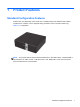
1 Product Features Standard Configuration Features Features may vary depending on the model. For a complete listing of the hardware and software installed on the computer, run the diagnostic utility (included on some computer models only). Figure 1-1 Configuration NOTE: This product features optional Powered USB ports. In the retail industry, “Powered USB” is also referred to as “USB + Power,” “USB Plus Power,” and “Retail USB.” In this document, these ports are referred to as “Powered USB.
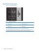
Front Panel Components Figure 1-2 Front Panel Components Table 1-1 Front Panel Components 1 Dual-State Power Button 5 USB Port 2 Power On Light 6 Hard Drive Activity Light 3 NIC Link Light 7 NIC Activity Light 4 Microphone Port 8 Headphone Port NOTE: The USB, microphone, and headphone ports are located behind a sliding door. The NIC link light indicates a network connection. The NIC activity light indicates network activity. The Power On Light is normally green when the power is on.
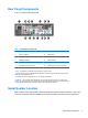
Rear Panel Components Figure 1-3 Rear Panel Components Table 1-2 Rear Panel Components 1 Power Cord Connector 8 Cash Drawer Connector 2 Powered USB 24V 9 USB Ports (4) 3 RJ-45 Network Connector 10 Powered USB 12V 4 Expansion Slot Cover 11 VGA Connector 5 Parallel Port 12 DisplayPort 6 PS/2 Mouse Connector (green) 13 PS/2 Keyboard Connector (purple) 7 Serial Connector (COM1) 14 Serial Connector (COM2) NOTE: Arrangement and number of connectors may vary by model.
2 Hardware Upgrades Warnings and Cautions Before performing upgrades be sure to carefully read all of the applicable instructions, cautions, and warnings in this guide. WARNING! To reduce the risk of personal injury from electrical shock, hot surfaces, or fire: Disconnect the power cord from the wall outlet and allow the internal system components to cool before touching. Do not plug telecommunications or telephone connectors into the network interface controller (NIC) receptacles.
Removing the Computer Access Panel To access internal components, you must remove the access panel: 1. Remove/disengage any security devices that prohibit opening the computer. 2. Remove all removable media, such as USB flash drives, from the computer. 3. Turn off the computer properly through the operating system, then turn off any external devices. 4. Disconnect the power cord from the power outlet and disconnect any external devices.
Replacing the Computer Access Panel 1. Align the tabs on the panel with the slots on the chassis then slide the panel towards the front of the chassis until it stops (1). 2. Tighten the thumbscrew to secure the access panel (2).
Removing the Front Bezel NOTE: The front bezel does not need to be removed for any of the procedures in this guide. It only needs to be removed if you are replacing the bezel or replacing the speaker or front I/O. 1. Remove/disengage any security devices that prohibit opening the computer. 2. Remove all removable media, such as USB flash drives, from the computer. 3. Turn off the computer properly through the operating system, then turn off any external devices. 4.
Replacing the Front Bezel Insert the three hooks on the bottom side of the bezel into the rectangular holes on the chassis (1) then rotate the top side of the bezel onto the chassis (2) and snap it into place. Figure 2-4 Replacing the Front Bezel System Board Connections Refer to the following illustration and table to identify the system board connectors. Figure 2-5 System Board Connections 8 No.
No. System Board Connector System Board Label Color Component 3 Riser Card Socket RPOS RISER white Riser Card 4 Memory Socket DIMM1 black Memory 5 SATA 3.
Installing Memory The computer comes with one double data rate 3 synchronous dynamic random access memory (DDR3-SDRAM) small outline dual inline memory module (SODIMM). DDR3-SDRAM SODIMM CAUTION: This product DOES NOT support DDR3 Ultra Low Voltage (DDR3U) memory. The processor is not compatible with DDR3U memory and if you plug DDR3U memory into the system board, it can cause the physical damage to the SODIMM or invoke system malfunction.
4. Disconnect the power cord from the power outlet and disconnect any external devices. CAUTION: You must disconnect the power cord and wait approximately 30 seconds for the power to drain before removing or installing a memory module. Regardless of the power-on state, voltage is always supplied to the memory module as long as the computer is plugged into an active AC outlet. Removing or installing a memory module while voltage is present may cause irreparable damage to the memory module or system board.
7. Slide the new SODIMM into the socket at approximately a 30° angle (1) then press the SODIMM down (2) so that the latches lock it in place. Figure 2-7 Installing a SODIMM NOTE: A memory module can be installed in only one way. Match the notch on the module with the tab on the memory socket. 8. Replace the access panel. 9. Reconnect the power cord and turn on the computer. 10. Lock any security devices that were disengaged when the access panel was removed.
Table 2-1 Riser Card Configurations No. Expansion Slots 1 PCI Express x1 Expansion Card slot 2 PCI Expansion Card slot 3 Powered Serial Port Expansion Card slot NOTE: Although there are two slots in each riser card, you can only install one expansion card in the riser card. The bottom slot on each card (3) is designed specifically for an HP Powered Serial Port expansion card. DO NOT attempt to plug any other type of card into the bottom slot.
If the powered serial ports have been configured for power from the factory, they will be covered by protective plastic caps. Turn off the computer and remove the caps before connecting powered serial devices. To install a Powered Serial Port expansion card: NOTE: The following procedure provides instructions for installing a Powered Serial Port expansion card. However, the procedure is basically the same for installing any full-height PCI expansion card or PC Express x1 expansion card. 1.
7. Before installing the expansion card, remove the expansion slot cover by sliding it out of the slot on the rear of the chassis. Figure 2-11 Removing an Expansion Slot Cover 8. Install the Powered Serial Port expansion card into the bottom socket on the riser card. Move the card toward the rear of the chassis so that the bracket on the card is aligned with the open slot on the rear of the chassis (1). Press the card straight down into the expansion socket on the riser card (2).
9. Close the expansion card retention latch. Figure 2-13 Closing the Expansion Card Retention Latch 10. Replace the computer access panel. 11. Reconnect the power cord and any external devices, then turn on the computer. 12. Lock any security devices that were disengaged when the access panel was removed. 13. Reconfigure the computer, if necessary. Configuring Powered Serial Ports The serial ports can be configured as standard (non-powered) serial ports or powered serial ports.
Installing an Optional 12-Volt Powered USB Expansion Card The computer is equipped with a 24-volt Powered USB connector on the riser card and one 12-volt Powered USB connector on the system board. It may also have an optional 12-volt Powered USB expansion card installed with three extra 12-volt Powered USB ports. The 24-volt Powered USB connector and the 12-volt Powered USB connector are keyed differently as a precaution to prevent connection errors.
7. Push outward on the tab located on the back of the expansion card retention latch inside the chassis (1) and rotate the latch open (2). Figure 2-15 Opening the Slot Cover Retention Latch 8. Before installing the expansion card, remove the expansion slot cover by sliding it out of the slot on the rear of the chassis.
9. Install the Powered USB expansion card into the PCI Express x1 socket on the riser card. Move the card toward the rear of the chassis so that the bracket on the card is aligned with the open slot on the rear of the chassis (1). Press the card straight down into the expansion socket on the riser card (2). Figure 2-17 Installing the Powered USB Expansion Card in the Riser Card 10. The cable included with the card has a single connector on one end and dual connectors on the other end.
11. Close the expansion card retention latch. Figure 2-19 Closing the Expansion Card Retention Latch 12. Replace the computer access panel. 13. Reconnect the power cord and any external devices, then turn on the computer. 14. Lock any security devices that were disengaged when the access panel was removed. 15. Reconfigure the computer, if necessary. Replacing the Riser Card There are two riser cards available from HP for this product. One has a PCI slot and the other has a PCI Express x1 slot.
6. If an expansion card is installed in one of the riser card expansion slots, push outward on the tab located on the back of the expansion card retention latch inside the chassis (1) and rotate the latch open (2). Figure 2-20 Opening the Slot Cover Retention Latch 7. If an expansion card is installed in one of the riser card expansion slots, remove the card.
8. To remove the riser card, pull back the arm on the back of the riser card socket (1), then lift the riser card out of the riser card socket (2). Figure 2-22 Removing the Riser Card 9. To install the new riser card, press the riser card firmly down into the riser card socket on the system board. Make sure that the tab on the end of the riser card bracket seats into the slot on the chassis when installing the card.
10. If an expansion card was removed from the old riser card or you are installing a new expansion card into the riser card, install the card into the appropriate slot on the new riser card. Move the card toward the rear of the chassis so that the bracket on the card is aligned with the open slot on the rear of the chassis (1). Press the card straight down into the expansion socket on the riser card (2). Figure 2-24 Installing an Expansion Card in the Riser Card 11.
12. Close the expansion card retention latch if it is open. Figure 2-26 Closing the Expansion Card Retention Latch 13. Replace the computer access panel. 14. Reconnect the power cord and any external devices, then turn on the computer. 15. Lock any security devices that were disengaged when the access panel was removed.
Replacing the Hard Drive NOTE: The HP RP3 computer supports 2.5-inch Serial ATA (SATA) internal hard drives. Before you remove the old hard drive, be sure to back up the data from the old hard drive so that you can transfer the data to the new hard drive. The 2.5-inch hard drive is enclosed in a carrier on the interior of the front panel. To replace the drive: 1. Remove/disengage any security devices that prohibit opening the computer. 2.
7. Press outward on the release latch located on the front panel just above the cable connection on the hard drive (1), then slide the carrier toward the center of the chassis and pull the carrier straight back from the front panel to remove it (2). Figure 2-28 Removing the Hard Drive Carrier 8. Press the retention arm on the rear of the carrier outward (1), then slide the drive forward and lift it out of the carrier (2).
9. Remove the four mounting screws from the sides of the hard drive. Figure 2-30 Removing the Mounting Screws 10. Install the four mounting screws on the sides of the new hard drive.
11. To install the hard drive in the carrier, align the mounting screws with the slots on the carrier, press the drive straight down into the carrier, then slide the drive back so that it locks inside the carrier. Ensure that the drive is properly seated in the carrier with the retention arm all the way down in the locked position. Figure 2-32 Installing the Hard Drive in the Carrier 12.
13. Connect the drive cables to the rear of the hard drive. Figure 2-34 Connecting the Hard Drive Cables 14. Replace the computer access panel. 15. Reconnect the power cord and turn on the computer. 16. Lock any security devices that were disengaged when the computer cover or access panel was removed. NOTE: No configuration of the SATA hard drive is necessary; the computer automatically recognizes it the next time you turn on the computer.
NOTE: The lifetime of the lithium battery can be extended by plugging the computer into a live AC wall socket. The lithium battery is only used when the computer is NOT connected to AC power. HP encourages customers to recycle used electronic hardware, HP original print cartridges, and rechargeable batteries. For more information about recycling programs, go to http://www.hp.com/ recycle. 1. Remove/disengage any security devices that prohibit opening the computer. 2.
b. To insert the new battery, slide one edge of the replacement battery under the holder’s lip with the positive side up. Push the other edge down until the clamp snaps over the other edge of the battery (2). Figure 2-36 Removing and Replacing a Coin Cell Battery (Type 2) NOTE: After the battery has been replaced, use the following steps to complete this procedure. 8. Replace the computer access panel. 9. Reconnect the power cord and any external devices, then turn on the computer. 10.
A External Security Devices Installing a Security Lock The security locks displayed below and on the following pages can be used to secure the computer.
HP Business PC Security Lock 1. Fasten the security cable by looping it around a stationary object. Figure A-3 Securing the Cable to a Fixed Object 2. Insert the cable lock into the cable lock slot on the back of the monitor and secure the lock to the monitor by inserting the key into the key hole on the rear of the lock and rotating the key 90 degrees.
3. Slide the security cable through the hole in the cable lock on the rear of the monitor. Figure A-5 Securing the Monitor 4. Use the bracket provided in the kit to secure other peripheral devices by laying the device cable across the center of the bracket (1) and inserting the security cable through one of the two holes in the bracket (2). Use the hole in the bracket that best secures the peripheral device cable.
5. Thread the keyboard and mouse cables through the computer chassis lock. Figure A-7 Threading the Keyboard and Mouse Cables 6. Screw the lock to the rear of the chassis using the screw provided.
7. Insert the plug end of the security cable into the lock (1) and push the button in (2) to engage the lock. Use the key provided to disengage the lock. Figure A-9 Engaging the Lock 8. When complete, all devices in your workstation will be secured.
Front Bezel Security The front bezel can be locked in place by installing a security screw provided by HP. To install the security screw: 1. Remove/disengage any security devices that prohibit opening the computer. 2. Remove all removable media, such as USB flash drives, from the computer. 3. Turn off the computer properly through the operating system, then turn off any external devices. 4. Disconnect the power cord from the power outlet and disconnect any external devices.
7. Install the security screw through the middle front bezel release tab to secure the front bezel to the chassis. Figure A-12 Installing the Front Bezel Security Screw 8. Replace the access panel. 9. Reconnect the power cord and any external devices, then turn on the computer. 10. Lock any security devices that were disengaged when the access panel was removed.
B Electrostatic Discharge A discharge of static electricity from a finger or other conductor may damage system boards or other static-sensitive devices. This type of damage may reduce the life expectancy of the device. Preventing Electrostatic Damage To prevent electrostatic damage, observe the following precautions: ● Avoid hand contact by transporting and storing products in static-safe containers. ● Keep electrostatic-sensitive parts in their containers until they arrive at static-free workstations.
C Computer Operating Guidelines, Routine Care and Shipping Preparation Computer Operating Guidelines and Routine Care Follow these guidelines to properly set up and care for the computer and monitor: ● Keep the computer away from excessive moisture, direct sunlight, and extremes of heat and cold. ● Operate the computer on a sturdy, level surface. Leave a 10.2-cm (4-inch) clearance on all vented sides of the computer and above the monitor to permit the required airflow.
4. Disconnect the power cord from the electrical outlet, then from the computer. 5. Disconnect the system components and external devices from their power sources, then from the computer. NOTE: Ensure that all boards are seated properly and secured in the board slots before shipping the computer. 6. Pack the system components and external devices in their original packing boxes or similar packaging with sufficient packing material to protect them.
Index A access panel locking and unlocking removal 5 replacement 6 audio connectors 2 L locks cable lock 32 front bezel 37 HP Business PC Security Lock 33 padlock 32 32 B battery replacement 29 C cash drawer connector 3 computer operating guidelines D DisplayPort M memory installation 10 specifications 10 E electrostatic discharge, preventing damage 39 expansion card installation 12 F front bezel removal 7 replacement 8 security 37 front panel components 2 H hard drive replacement 25 I installation g