Hardware Reference Guide HP RP7 Retail System Model 7800
© Copyright 2012 Hewlett-Packard Development Company, L.P. The information contained herein is subject to change without notice. Microsoft, Windows, and Windows Vista are either trademarks or registered trademarks of Microsoft Corporation in the United States and/or other countries. The only warranties for HP products and services are set forth in the express warranty statements accompanying such products and services. Nothing herein should be construed as constituting an additional warranty.
About This Book This guide provides basic information for upgrading this computer model. WARNING! Text set off in this manner indicates that failure to follow directions could result in bodily harm or loss of life. CAUTION: Text set off in this manner indicates that failure to follow directions could result in damage to equipment or loss of information. NOTE: ENWW Text set off in this manner provides important supplemental information.
iv About This Book ENWW
Table of contents 1 Product Features ............................................................................................................................................ 1 Standard Features ................................................................................................................................ 1 Optional HP RP7 Accessories .............................................................................................................. 2 Front Panel Controls .....................
Appendix A Troubleshooting .......................................................................................................................... 61 Interpreting POST Diagnostic Front Panel LEDs and Audible Codes ................................................ 61 Appendix B Electrostatic Discharge .............................................................................................................. 64 Preventing Electrostatic Damage ..............................................................
1 Product Features Standard Features The HP RP7 Retail System features include: ENWW ● Designed for long-term deployment within general retail, hospitality, and other retail markets ● Choice of associate facing touchscreen: ◦ 15” Resistive ◦ 15” Projective Capacitive ◦ 17” Projective Capacitive ● Cable management features ● Water and dust resistant touch screens ● Flexible use with display tilt and height adjustments ● Three optional peripherals that can be integrated: ◦ HP Retail Inte
● Chipset choices ● DDR3 memory ● Operating system choices ● Integrated NIC and WiFi (some models) ● USB+PWR and cash drawer ports ● Hard drive and SSD choices ● RAID level 0,1 capable (RAID 1 can be HP factory preconfigured) ● Manageability tools ● Secure USB port (security screw provided) ● Energy Star 5 qualified, EU Compliant, RoHS2 Compliant ● 87% energy efficient internal power supply adapter ● HP Limited Warranty, 3/3/3 standard: 3 years parts, 3 years labor, and 3 years on-sit
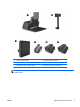
1 HP RP7 Adjustable Stand 4 HP Retail Integrated Webcam 2 HP Retail RP7 VFD Customer Display 5 HP Retail Integrated Fingerprint Reader 3 HP Retail RP7 10.4” Customer Display 6 HP Retail Integrated Dual-Head MSR NOTE: A stand-alone VFD that is mounted on a separate stand is also available from HP (not pictured above).
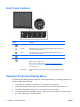
Front Panel Controls Control Function 1 Menu Opens the On-Screen Display (OSD) main menu. 2 – (Minus) If the OSD menu is on, tap to navigate backward through the OSD menu and decrease adjustment levels. 3 + (Plus) If the OSD menu is on, tap to navigate forward through the OSD menu and increase adjustment levels. 4 OK If the OSD menu is on, tap to select a menu item. 5 Power LED Green = Fully powered.
5. To select an item from the OSD Menu, use the + or – icons to scroll to and highlight your selection, then tap the OK icon to select that function. 6. Adjust the item using the + or – icons on the front panel to adjust the scale. 7. After adjusting the function, select Save and Return, or Cancel if you don’t want to save the setting, then select Exit from the Main Menu. The following table lists the OSD Main menu items with a brief descriptions of each item.
Rear I/O Panel Components 1 Hard Drive Activity Light 9 Secured USB Port 2 Line-Out Connector for powered audio devices (green) 10 Line-In Audio Connector (blue) 3 DVI Connector (for a secondary display or the optional HP Retail RP7 10.4” Customer Display) 11 Parallel Port 4 PS/2 Mouse/Keyboard Connector 12 RJ-45 Network Connector 5 DC Out Power Connector (for the optional HP Retail RP7 10.
2 Hardware Upgrades Tools Needed A Phillips, Torx, or flat blade screwdriver is needed for most of the procedures described in this guide. Warnings and Cautions Before performing upgrades be sure to carefully read all of the applicable instructions, cautions, and warnings in this guide. WARNING! To reduce the risk of personal injury from electrical shock, hot surfaces, or fire: Disconnect the power cord from the wall outlet and allow the internal system components to cool before touching.
This apparatus is intended to be supported by UL or CSA Listed wall mount bracket. HP recommends that you use an HP Quick Release mounting bracket for wall mounting (part number EM870AA). CAUTION: To attach a third-party mounting solution to the RP7, four 4 mm, 0.7 pitch, and 10 mm long screws are required. Longer screws must not be used because they may damage the system.
ENWW 4. Pull the power supply cover back then lift if up and off the unit. 5. Remove the decorative panel on the rear of the unit by gently prying the panel away from the base at the tab locations on the top and sides of the panel as indicated below (1). Then pull the top of the panel away from the base (2) and push straight down on the panel to release the bottom tabs (3).
10 6. Slide down the two levers on the upper corners of the rear I/O panel (1) and rotate the cover off (2). 7. Attach the RP7 display head to the stand's mounting bracket by aligning the slots on the display head with the hooks on the mounting bracket and sliding the display down (1). Install the three screws included with the stand through the mounting bracket and into the display head to secure it in place (2).
8. Slide the mounting bracket cover down over the stand's mounting bracket. 9. Rotate open the small door at the base of the power supply housing (1) and slide the power supply brick into the housing (2). NOTE: Make sure that the side of the power supply with the label and rubber foot are facing the front of the unit when sliding in the power supply.
10. Close the small door at the base of the power supply housing (1). Route the power supply cord through side of the base, then out through the center of the base (2) and up through the cable retainer on the neck of the stand. Insert the cord into the cable retainer clip next to the power port (3) and connect the cord to the DC In power port. 11. Route the AC power cord through the bottom of the stand's base, then through the cavity inside the base and connect the cord to the power supply brick.
12. Snap the decorative panel back onto the rear of the base. 13. Replace the power supply cover by lowering it down over the neck of the base then sliding it back until it snaps in place.
14. Replace the rear I/O cover by placing the hooks on the bottom of the cover into the slots on the bottom of the chassis (1). Then rotate the top of the I/O cover up so that it snaps securely onto the chassis (2). 15. You can adjust the monitor stand height and tilt to a variety of positions. Choose a position that is the most ergonomically appropriate for your usage. Routing Cables to External Devices 1. Turn off the computer properly through the operating system, then turn off any external devices.
ENWW 3. Slide down the two levers on the upper corners of the rear I/O panel (1) and rotate the cover off (2). 4. Pull the power supply cover back then lift if up and off the unit.
5. Remove the decorative panel on the rear of the unit by gently prying the panel away from the base at the tab locations on the top and sides of the panel as indicated below (1). Then pull the top of the panel away from the base (2) and push straight down on the panel to release the bottom tabs (3). 6. Route the cables underneath the rear of the base, then through the hole in the center of the base, then up through the cable retainer on the neck of the stand and into the appropriate I/O port.
ENWW 7. Snap the decorative panel back onto the rear of the base. 8. Replace the power supply cover by lowering it down over the neck of the base then sliding it back until it snaps in place.
9. Replace the rear I/O cover by placing the hooks on the bottom of the cover into the slots on the bottom of the chassis (1). Then rotate the top of the I/O cover up so that it snaps securely onto the chassis (2). 10. Reconnect the power cord and press the power button. Installing Optional Integrated USB Modules There are three optional integrated USB modules available from HP (sold separately).
The procedure for installing an integrated USB module is the same for all modules. To install a USB module: 1. Turn off the computer properly through the operating system, then turn off any external devices. 2. Disconnect the power cord from the power outlet. CAUTION: Regardless of the power-on state, voltage is always present on the system board as long as the system is plugged into an active AC outlet. You must disconnect the power cord to avoid damage to the internal components of the computer. 3.
4. Press inward on the buttons located near the bottom sides of the display head's back panel (1) then slide the back panel up and off the display head (2). 5. Remove the two screws that attach the USB cover plate to the display head (1) then slide the cover plate off the display head (2). Remove only the cover plate that is in the location where you want to install the USB module.
6. Pull the plug that is inserted in the USB port out of the port. NOTE: Some models do not have plugs in the USB ports. 7. ENWW Slide the screw hole cover plate on the module back (1) and insert the USB connector on the module into the USB port (2).
22 8. Install the two screws that were previously removed (1) and slide the cover plate on the module forward to cover the screws (2). 9. Slide the display head's back panel down onto the rear of the display head.
10. Replace the rear I/O cover by placing the hooks on the bottom of the cover into the slots on the bottom of the chassis (1). Then rotate the top of the I/O cover up so that it snaps securely onto the chassis (2). 11. Reconnect the power cord and press the power button. Installing an Optional HP Retail RP7 10.4” Customer Display 1. Turn off the computer properly through the operating system, then turn off any external devices. 2. Disconnect the power cord from the power outlet.
24 3. Slide down the two levers on the upper corners of the rear I/O panel (1) and rotate the cover off (2). 4. Pull the power supply cover back then lift if up and off the unit.
ENWW 5. Remove the decorative panel on the rear of the unit by gently prying the panel away from the base at the tab locations on the top and sides of the panel as indicated below (1). Then pull the top of the panel away from the base (2) and push straight down on the panel to release the bottom tabs (3). 6. Connect the audio, DVI, and power cables to the customer display. Insert the DVI cable into the retainer clip at the base of the display head. Installing an Optional HP Retail RP7 10.
26 7. Route the audio, DVI, and power cables through the hole in the customer display back plate (1). Connect the back plate to the customer display by aligning the hooks on the back plate with the slots on the back of the display and sliding the back plate up (2) so that the screw holes on the back plate are aligned with the screw holes on the display. Install the two screws to secure the back plate to the display (3). 8.
9. Route the audio, DVI, and power cables through the rear of the base and out the front of the base, then up through the cable retainer on the neck of the RP7 stand and connect the cables to the RP7 I/O ports. 10. Snap the decorative panel onto the rear of the base. ENWW Installing an Optional HP Retail RP7 10.
11. Slide the back plate mounting bracket into the mounting hole on the rear of the RP7 base (1), and install the two screws included with the customer display into the screw holes on top of the mounting bracket (2). 12. Replace the power supply cover by lowering it down over the neck of the base then sliding it back until it snaps in place.
13. Replace the rear I/O cover by placing the hooks on the bottom of the cover into the slots on the bottom of the chassis (1). Then rotate the top of the I/O cover up so that it snaps securely onto the chassis (2). 14. Reconnect the power cord and press the power button on both displays. Installing an Optional HP Retail RP7 VFD Customer Display The integrated VFD customer display can be installed with no poles attached, or with one or two poles attached, depending on the desired height of the VFD. 1.
30 3. Slide down the two levers on the upper corners of the rear I/O panel (1) and rotate the cover off (2). 4. Pull the power supply cover back then lift if up and off the unit.
ENWW 5. Remove the decorative panel on the rear of the unit by gently prying the panel away from the base at the tab locations on the top and sides of the panel as indicated below (1). Then pull the top of the panel away from the base (2) and push straight down on the panel to release the bottom tabs (3). 6. If you are installing the VFD with no poles attached, insert the VFD cable through the center of the mounting bracket (1) and slide the VFD onto the mounting bracket (2).
32 7. If you are installing the VFD with poles attached. slide either one or two poles onto the mounting bracket, depending on the desired height of the VFD. Thread the VFD cable through the top of the pole assembly and out the bottom of the mounting bracket (1), then slide the VFD onto the pole assembly (2). 8. Route the VFD cable through the hole in the decorative panel that was included with the VFD, then through the rear of the base (1) and out the front of the base.
9. Wrap the excess extension cable around the hooks on the rear of the base. 10. Snap the decorative plate onto the rear of the base.
11. Slide the VFD mounting bracket into the mounting hole on the rear of the RP7 base (1), and install the two screws included with the VFD into the screw holes on top of the mounting bracket (2). 12. Replace the power supply cover by lowering it down over the neck of the base then sliding it back until it snaps in place.
13. Replace the rear I/O cover by placing the hooks on the bottom of the cover into the slots on the bottom of the chassis (1). Then rotate the top of the I/O cover up so that it snaps securely onto the chassis (2). 14. Reconnect the power cord and press the power button.
Installing Additional Memory The computer comes with double data rate 3 synchronous dynamic random access memory (DDR3SDRAM) small outline dual inline memory modules (SODIMMs). SODIMMs The memory sockets on the system board can be populated with up to two industry-standard SODIMMs. These memory sockets are populated with at least one preinstalled SODIMM. To achieve the maximum memory support, you can populate the system board with up to 8-GB of memory.
Populating SODIMM Sockets There are two SODIMM sockets on the system board, with one socket per channel. The sockets are labeled DIMM1 and DIMM3. The DIMM1 socket operates in memory channel A. The DIMM3 socket operates in memory channel B. The system will automatically operate in single channel mode, dual channel mode, or flex mode, depending on how the SODIMMs are installed. ● The system will operate in single channel mode if the SODIMM sockets are populated in one channel only.
38 3. Slide down the two levers on the upper corners of the rear I/O panel (1) and rotate the cover off (2). 4. Press inward on the buttons located near the bottom sides of the display head's back panel (1) then slide the back panel up and off the display head (2).
ENWW 5. Press down on the lever at the to of the memory access door (1) and rotate the door open (2). 6. To remove a SODIMM, press outward on the two latches on each side of the SODIMM (1) then pull the SODIMM out of the socket (2).
7. To install a SODIMM, slide the new SODIMM into the socket at approximately a 30° angle (1) then press the SODIMM down into the socket (2) so that the latches lock it in place. NOTE: A memory module can be installed in only one way. Match the notch on the module with the tab on the memory socket. 8. 40 Close the memory access door.
9. Slide the display head's back panel down onto the rear of the display head. 10. Replace the rear I/O cover by placing the hooks on the bottom of the cover into the slots on the bottom of the chassis (1). Then rotate the top of the I/O cover up so that it snaps securely onto the chassis (2). 11. Reconnect the power cord and press the power button. The computer automatically recognizes the additional memory when you turn on the computer.
Removing and Installing a Hard Drive CAUTION: If you are replacing a hard drive, be sure to back up the data from the old drive so that you can transfer the data to the new drive. 1. Turn off the computer properly through the operating system, then turn off any external devices. 2. Disconnect the power cord from the power outlet. CAUTION: Regardless of the power-on state, voltage is always present on the system board as long as the system is plugged into an active AC outlet.
ENWW 5. Open the hard drive door (1), then grasp the pull tab on the side of the hard drive and pull the hard drive out of the drive bay (2). 6. Remove the four screws from the sides of the hard drive carrier (1) and lift the hard drive out of the carrier (2).
44 7. Place the new hard drive into the carrier (1) and install the four screws into the sides of the carrier (2). 8. Slide the hard drive/carrier assembly into the drive bay (1) and close the hard drive door (2).
9. Slide the display head's back panel down onto the rear of the display head. 10. Replace the rear I/O cover by placing the hooks on the bottom of the cover into the slots on the bottom of the chassis (1). Then rotate the top of the I/O cover up so that it snaps securely onto the chassis (2). 11. Reconnect the power cord and press the power button.
Replacing the Battery The battery that comes with the computer provides power to the real-time clock. When replacing the battery, use a battery equivalent to the battery originally installed in the computer. The computer comes with a 3-volt lithium coin cell battery. WARNING! The computer contains an internal lithium manganese dioxide battery. There is a risk of fire and burns if the battery is not handled properly. To reduce the risk of personal injury: Do not attempt to recharge the battery.
ENWW 4. Slide down the two levers on the upper corners of the rear I/O panel (1) and rotate the cover off (2). 5. Disconnect all cables from the rear I/O connectors. 6. Press inward on the buttons located near the bottom sides of the display head's back panel (1) then slide the back panel up and off the display head (2).
48 7. Remove the RP7 display head from the stand by removing the three screws that attach the stand's mounting bracket to the display head (1) then slide the display up and off the mounting bracket (2). 8. Lay the display head face down on a surface covered by a clean, dry cloth. 9. Open the memory access door (1), disconnect the DisplayPort power cable (2) and signal cable (3), then swing the antenna bracket out away from the chassis (4).
10. Remove the five screws that secure the metal plate on the back of the display head (1) and lift the metal plate off the display head (2). 11. Note which side of the battery is the positive side so that the new battery has the same orientation and pull the battery out of its holder.
12. Insert the new battery. Ensure that the positive side of the new battery is oriented in the same direction as the battery that was removed. 13. Place the metal plate on the back of the display head (1) and secure it to the display head with the five screws that were previously removed (2).
14. Swing the antenna bracket in toward the chassis (1), connect the DisplayPort signal cable (2) and power cable (3), and close the memory access door (4). 15. Attach the RP7 display head to the stand's mounting bracket by aligning the slots on the display head with the hooks on the mounting bracket and sliding the display down (1). Install the three screws through the mounting bracket and into the display head to secure it in place (2).
16. Slide the display head's back panel down onto the rear of the display head. 17. Reconnect all cables to the rear I/O connectors. 18. Replace the rear I/O cover by placing the hooks on the bottom of the cover into the slots on the bottom of the chassis (1). Then rotate the top of the I/O cover up so that it snaps securely onto the chassis (2).
19. Slide the mounting bracket cover down over the stand's mounting bracket. 20. Plug in the power cord and press the power button. Using the USB Security Cover 1. Turn off the computer properly through the operating system, then turn off any external devices. 2. Disconnect the power cord from the power outlet. CAUTION: Regardless of the power-on state, voltage is always present on the system board as long as the system is plugged into an active AC outlet.
54 4. Push inward on the tab at the bottom of the USB security cover (1) and rotate the bottom of the cover up (2) to remove it. 5. Insert the USB device into the USB port.
6. Insert the top of the USB security cover into the I/O panel at an angle with the bottom of the cover slightly raised (1), then rotate the bottom down so that the cover snaps in place (2). NOTE: If the USB device has a cable, place the cable in the channel on the side of the security cover. 7. If you want to secure the USB port, remove the security screw from the inside of the rear I/O panel and install the screw in the screw hole on the side of the USB security cover.
8. Replace the rear I/O cover by placing the hooks on the bottom of the cover into the slots on the bottom of the chassis (1). Then rotate the top of the I/O cover up so that it snaps securely onto the chassis (2). 9. Reconnect the power cord and press the power button. Securing the RP7 to a Counter Top 1. Turn off the computer properly through the operating system, then turn off any external devices. 2. Disconnect the power cord from the power outlet.
4. There are two screw holes on the base of the stand. Fasten the stand to the counter top using the appropriate fastening devices for your surface. NOTE: HP supplies wood screws for securing the base to a wooden surface. 5. Replace the power supply cover by lowering it down over the neck of the base then sliding it back until it snaps in place. 6. Reconnect the power cord and press the power button.
Padlock A padlock can be used to secure the RP7 rear panel.
3 Configuring the Software Touch Screen Calibration You do not need to install the touch driver software for Microsoft Windows 7 or POSReady 7. Touch drivers are already included in those operating systems for this monitor. HP recommends that you calibrate the touch screen before using the system to ensure that the touch point registers on the screen where the stylus or finger touches the screen.
Configuring Powered Serial Ports The serial ports can be configured as standard (non-powered) serial ports or powered serial ports. Some devices use a powered serial port. If the serial port is configured as a powered port, devices that support a powered serial interface do not require an external power source. NOTE: The computer ships with all serial ports configured in standard serial mode by default unless the powered serial port AV numbers are ordered.
A Troubleshooting Interpreting POST Diagnostic Front Panel LEDs and Audible Codes This section covers the front panel LED codes as well as the audible codes that may occur before or during POST that do not necessarily have an error code or text message associated with them. WARNING! When the computer is plugged into an AC power source, voltage is always applied to the system board.
Table A-1 Diagnostic Front Panel LEDs and Audible Codes (continued) Activity Beeps Possible Cause Recommended Action Red Power LED flashes four times, once every second, followed by a two second pause. Beeps stop after fifth iteration but LEDs continue until problem is solved. 4 Power failure (power supply is overloaded). 1. Ensure the DC power cable is plugged into the I/O panel. 2. Check if a device is causing the problem by removing ALL attached devices (such as a hard drive).
Table A-1 Diagnostic Front Panel LEDs and Audible Codes (continued) Activity Beeps Possible Cause Recommended Action Power LED flashes 12 times, once every second, followed by a two second pause. Beeps stop after third iteration and the computer reboots. 12 Health timer expired. None. System does not power on and LEDs are not flashing. None System unable to power on. Press and hold the power button for less than 4 seconds. If the hard drive LED turns green, the power button is working correctly.
B Electrostatic Discharge A discharge of static electricity from a finger or other conductor may damage system boards or other static-sensitive devices. This type of damage may reduce the life expectancy of the device. Preventing Electrostatic Damage To prevent electrostatic damage, observe the following precautions: ● Avoid hand contact by transporting and storing products in static-safe containers. ● Keep electrostatic-sensitive parts in their containers until they arrive at static-free workstations.
C Computer Operating Guidelines, Routine Care and Shipping Preparation Computer Operating Guidelines and Routine Care Follow these guidelines to properly set up and care for the computer and monitor: ● Although the display is water resistant, it is best to keep it away from excessive moisture, direct sunlight, and extremes of heat and cold. ● Never restrict the airflow into the computer by blocking any vents or air intakes. ● Never operate the computer with the cover or side panel removed.
Shipping Preparation Follow these suggestions when preparing to ship the computer: 1. Back up the hard drive files. Be sure that the backup media is not exposed to electrical or magnetic impulses while stored or in transit. NOTE: The hard drive locks automatically when the system power is turned off. 66 2. Remove and store all removable media. 3. Turn off the computer and external devices. 4. Disconnect the power cord from the electrical outlet, then from the computer. 5.
Index A accessories 2 R rear I/O panel B battery, replacing 46 S security locks 57 serial ports, configuring for power 60 shipping preparation 66 stand, installing 8 C cable routing 14 components front 4 rear I/O panel 6 computer operating guidelines 65 counter top, securing 56 customer display, installing 23 E electrostatic discharge, preventing damage 64 F features 1 fingerprint reader, installing front panel controls 4 6 T touch screen calibration 59 maintenance 65 troubleshooting 61 U USB security